2000 SUZUKI SWIFT check engine light
[x] Cancel search: check engine lightPage 45 of 698

0B-16 MAINTENANCE AND LUBRICATION
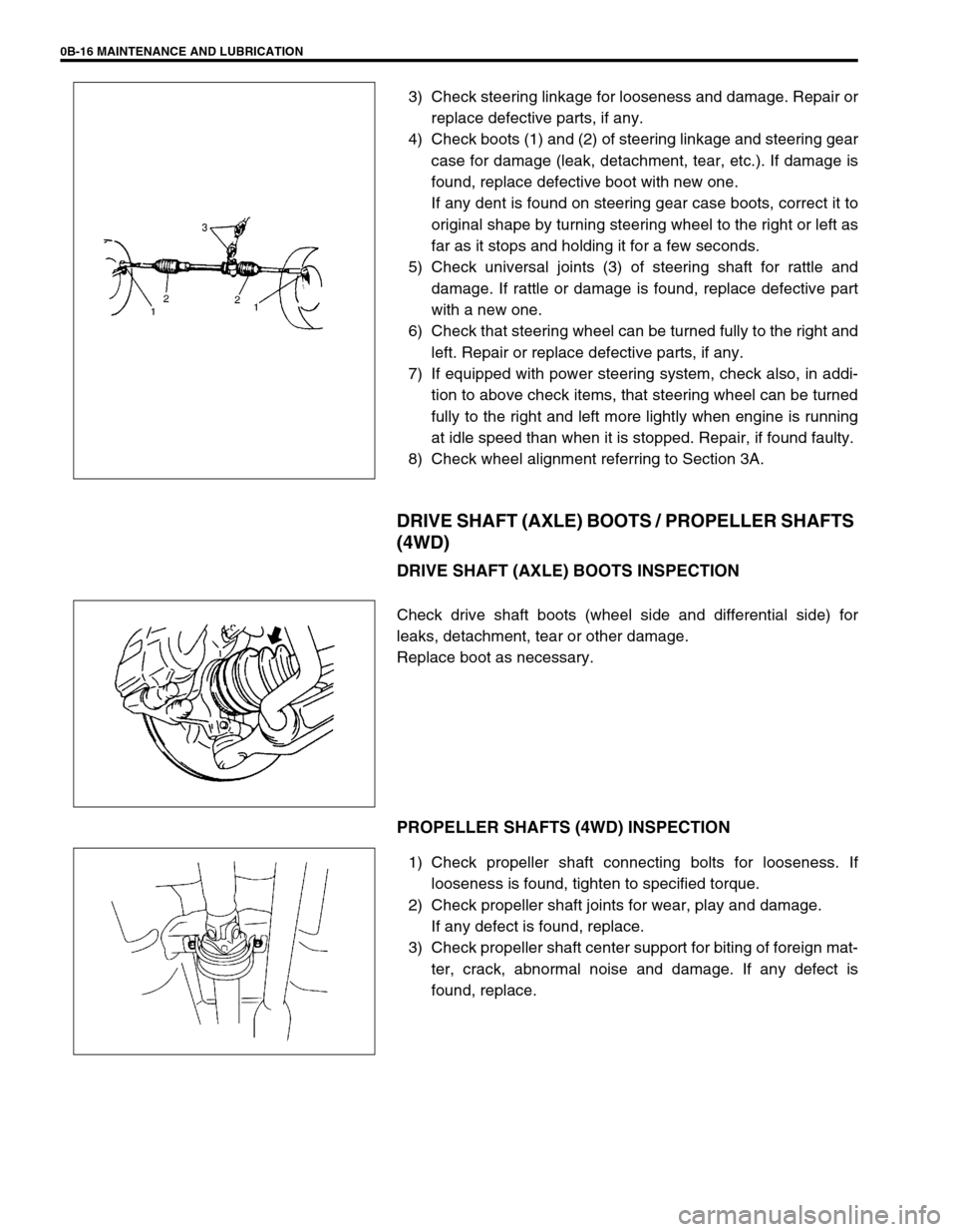
3) Check steering linkage for looseness and damage. Repair or
replace defective parts, if any.
4) Check boots (1) and (2) of steering linkage and steering gear
case for damage (leak, detachment, tear, etc.). If damage is
found, replace defective boot with new one.
If any dent is found on steering gear case boots, correct it to
original shape by turning steering wheel to the right or left as
far as it stops and holding it for a few seconds.
5) Check universal joints (3) of steering shaft for rattle and
damage. If rattle or damage is found, replace defective part
with a new one.
6) Check that steering wheel can be turned fully to the right and
left. Repair or replace defective parts, if any.
7) If equipped with power steering system, check also, in addi-
tion to above check items, that steering wheel can be turned
fully to the right and left more lightly when engine is running
at idle speed than when it is stopped. Repair, if found faulty.
8) Check wheel alignment referring to Section 3A.
DRIVE SHAFT (AXLE) BOOTS / PROPELLER SHAFTS
(4WD)
DRIVE SHAFT (AXLE) BOOTS INSPECTION
Check drive shaft boots (wheel side and differential side) for
leaks, detachment, tear or other damage.
Replace boot as necessary.
PROPELLER SHAFTS (4WD) INSPECTION
1) Check propeller shaft connecting bolts for looseness. If
looseness is found, tighten to specified torque.
2) Check propeller shaft joints for wear, play and damage.
If any defect is found, replace.
3) Check propeller shaft center support for biting of foreign mat-
ter, crack, abnormal noise and damage. If any defect is
found, replace.
Page 50 of 698

MAINTENANCE AND LUBRICATION 0B-21
STEERING
Check to ensure that steering wheel is free from instability, or abnormally heavy feeling.
Check that the vehicle does not wander or pull to one side.
ENGINE
Check that engine responds readily at all speeds.
Check that engine is free from abnormal noise and abnormal vibration.
BODY, WHEELS AND POWER TRANSMITTING SYSTEM
Check that body, wheels and power transmitting system are free from abnormal noise and abnormal vibration or
any other abnormal condition.
METERS AND GAUGE
Check that speedometer, odometer, fuel meter, temperature gauge, etc. are operating accurately.
LIGHTS
Check that all lights operate properly.
WINDSHIELD DEFROSTER
Periodically check that air comes out from defroster outlet when operating heater or air conditioning.
Set mode control lever to defroster position and fan switch lever to “HI” position for this check.
RECOMMENDED FLUIDS AND LUBRICANTS
Engine oil SE, SF, SG, SH or SJ grade (Refer to “ENGINE OIL AND OIL FILTER”
in this section for engine oil viscosity.)
Engine coolant
(Ethylene glycol base coolant)“Antifreeze/Anticorrosion coolant”
Brake fluid DOT 3
Manual transmission oil Refer to “M/T OIL CHANGE” in Section 7A.
Transfer oil (4WD) Refer to “TRANSFER OIL CHANGE” in Section 7D.
Differential oil (4WD) Refer to “DIFFERENTIAL OIL CHANGE” in Section 7F.
Automatic transmission fluid
An equivalent of DEXRON
®-III
Door hinges Engine oil or water resistance chassis grease
Hood latch assembly Engine oil or water resistance chassis grease
Key lock cylinder Spray lubricant
Page 101 of 698

1B-36 AIR CONDITIONING (OPTIONAL)
A/C SWITCH
REMOVAL AND INSTALLATION
Refer to “HEATER CONTROL ASSEMBLY” in Section 1A.
INSPECTION
Press A/C switch button and check if there is continuity
between terminals “A” and “B”.
Connect battery voltage (+) to terminal “C” and (–) to termi-
nal “A”, and then press A/C Switch button and check if indi-
cator lamp lights.
RADIATOR/CONDENSER COOLING FAN
MOTOR RELAY No.1, No.2 and No.3
INSPECTION
Refer to “RADIATOR FAN RELAY” in Section 6B.
COMPRESSOR
REMOVAL
1) Run engine at idle speed with air conditioning ON for 10 min-
utes. After that stop the engine.
2) Disconnect negative (–) cable at battery.
3) Recover refrigerant from refrigeration system by referring to
“RECOVERY” in this section.
4) Remove front bumper by referring to “FRONT BUMPER” in
Section 8.
5) Remove engine food cover (1) from vehicle body.
NOTE:
The amount of removed compressor oil must be mea-
sured for replenishing compressor oil.
Page 145 of 698

3B1-4 ELECTRICAL POWER STEERING (P/S) SYSTEM
DIAGNOSIS
The P/S system in this vehicle is controlled by P/S control module. P/S control module has an on-board diagnos-
tic system which detects a malfunction in this system.
When diagnosing troubles, be sure to have full understanding of the outline of “ON-BOARD DIAGNOSTIC SYS-
TEM” and each item in “PRECAUTION IN DIAGNOSING TROUBLE” and execute diagnosis according to “SYS-
TEM CHECK FLOW TABLE”.
ON-BOARD DIAGNOSTIC SYSTEM
P/S control module performs on-board diagnosis (self-diagnosis)
on the system and operates “EPS” warning lamp (1) (malfunction
indicator lamp) as follows.
Malfunction indicator lamp (“EPS” warning lamp) lights when
the ignition switch is turned to ON position (but the engine at
stop) regardless of the condition of P/S control system. This
is only to check the malfunction indicator lamp (“EPS” warn-
ing lamp) bulb and its circuit.
If the areas monitored by P/S control module is free from any
trouble after the engine start (while engine is running), mal-
function indicator lamp (“EPS” warning lamp) turns OFF.
When P/S control module detects a trouble which has
occurred in the areas it monitors, malfunction indicator lamp
(“EPS” warning lamp) turns ON while the engine is running
to warn the driver of such occurrence of trouble and at the
same time it stores the exact trouble area in memory inside
of P/S control module.
PRECAUTIONS IN DIAGNOSING TROUBLES
Take a note of DTC indicated first.
Be sure to read “PRECAUTIONS FOR ELECTRONIC CIRCUIT SERVICE” in Section 0A before inspection
and observe what is written there.
When two or more troubles have occurred, their DTCs are indicated 3 times each starting with the smallest
code number and up.
DTC C1122 (DTC No.22) (engine speed signal failure) is indicated when ignition switch is ON position and
engine is not running but if indication changes to a normal one when engine is started, it means nothing
abnormal.
As DTC is stored in memory of P/S control module, be sure to clear memory after repair by performing the
procedure described in “DTC CLEARANCE”.
1
Page 148 of 698

ELECTRICAL POWER STEERING (P/S) SYSTEM 3B1-7
CUSTOMER QUESTIONNAIRE (EXAMPLE)
MALFUNCTION INDICATOR LAMP
(“EPS” WARNING LAMP) CHECK
1) Turn ignition switch to ON position (but without running
engine), check that malfunction indicator lamp (“EPS” warn-
ing lamp) lights up. If lamp does not light up, go to “TABLE
A”. If lamp flashes, go to “TABLE B”.
2) Start engine and check that malfunction indictor lamp
(“CHECK ENGIE” light) turns OFF.
If lamp comes OFF, P/S system is in good condition.
Page 168 of 698

ELECTRICAL POWER STEERING (P/S) SYSTEM 3B1-27
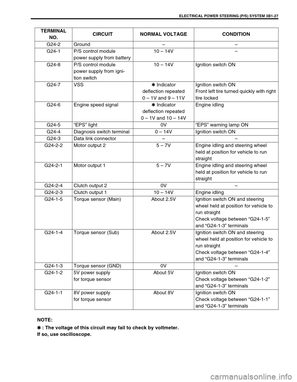
TERMINAL
NO.CIRCUIT NORMAL VOLTAGE CONDITION
G24-2 Ground––
G24-1 P/S control module
power supply from battery10 – 14V–
G24-8 P/S control module
power supply from igni-
tion switch10 – 14V Ignition switch ON
G24-7 VSS✱ Indicator
deflection repeated
0 – 1V and 9 – 11VIgnition switch ON
Front left tire turned quickly with right
tire locked
G24-6 Engine speed signal✱ Indicator
deflection repeated
0 – 1V and 10 – 14VEngine idling
G24-5“EPS” light 0V“EPS” warning lamp ON
G24-4 Diagnosis switch terminal 0 – 14V Ignition switch ON
G24-3 Data link connector––
G24-2-2 Motor output 2 5 – 7V Engine idling and steering wheel
held at position for vehicle to run
straight
G24-2-1 Motor output 1 5 – 7V Engine idling and steering wheel
held at position for vehicle to run
straight
G24-2-4 Clutch output 2 0V–
G24-2-3 Clutch output 1 10 – 14V Engine idling
G24-1-5 Torque sensor (Main) About 2.5V Ignition switch ON and steering
wheel held at position for vehicle to
run straight
Check voltage between “G24-1-5”
and “G24-1-3” terminals
G24-1-4 Torque sensor (Sub) About 2.5V Ignition switch ON and steering
wheel held at position for vehicle to
run straight
Check voltage between “G24-1-4”
and “G24-1-3” terminals
G24-1-3 Torque sensor (GND) 0V–
G24-1-2 5V power supply
for torque sensorAbout 5V Ignition switch ON
Check voltage between “G24-1-2”
and “G24-1-3” terminals
G24-1-1 8V power supply
for torque sensorAbout 8V Ignition switch ON
Check voltage between “G24-1-1”
and “G24-1-3” terminals
NOTE:
✱
✱✱ ✱ : The voltage of this circuit may fail to check by voltmeter.
If so, use oscilloscope.
Page 280 of 698

BRAKES 5-7
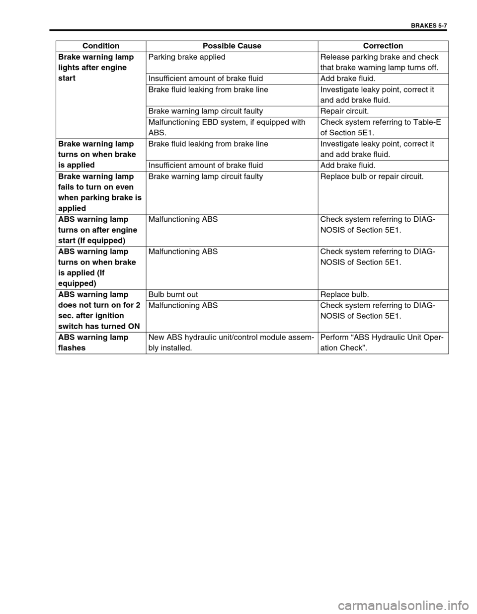
Brake warning lamp
lights after engine
startParking brake applied Release parking brake and check
that brake warning lamp turns off.
Insufficient amount of brake fluid Add brake fluid.
Brake fluid leaking from brake line Investigate leaky point, correct it
and add brake fluid.
Brake warning lamp circuit faulty Repair circuit.
Malfunctioning EBD system, if equipped with
ABS.Check system referring to Table-E
of Section 5E1.
Brake warning lamp
turns on when brake
is appliedBrake fluid leaking from brake line Investigate leaky point, correct it
and add brake fluid.
Insufficient amount of brake fluid Add brake fluid.
Brake warning lamp
fails to turn on even
when parking brake is
appliedBrake warning lamp circuit faulty Replace bulb or repair circuit.
ABS warning lamp
turns on after engine
start (If equipped)Malfunctioning ABS Check system referring to DIAG-
NOSIS of Section 5E1.
ABS warning lamp
turns on when brake
is applied (If
equipped)Malfunctioning ABS Check system referring to DIAG-
NOSIS of Section 5E1.
ABS warning lamp
does not turn on for 2
sec. after ignition
switch has turned ONBulb burnt out Replace bulb.
Malfunctioning ABS Check system referring to DIAG-
NOSIS of Section 5E1.
ABS warning lamp
flashesNew ABS hydraulic unit/control module assem-
bly installed.Perform “ABS Hydraulic Unit Oper-
ation Check”. Condition Possible Cause Correction
Page 371 of 698

6-2 ENGINE GENERAL INFORMATION AND DIAGNOSIS
ENGINE DIAGNOSIS ......................................... 6-6
GENERAL DESCRIPTION ............................. 6-6
ON-BOARD DIAGNOSTIC SYSTEM
(VEHICLE WITH IMMOBILIZER INDICATOR
LAMP) ............................................................. 6-7
ON-BOARD DIAGNOSTIC SYSTEM
(VEHICLE WITHOUT IMMOBILIZER
INDICATOR LAMP) ...................................... 6-10
PRECAUTION IN DIAGNOSING
TROUBLE ..................................................... 6-11
ENGINE DIAGNOSTIC FLOW TABLE ......... 6-12
CUSTOMER PROBLEM INSPECTION
FORM (EXAMPLE) ................................... 6-14
MALFUNCTION INDICATOR LAMP (MIL)
CHECK...................................................... 6-15
DIAGNOSTIC TROUBLE CODE (DTC)
CHECK...................................................... 6-15
DIAGNOSTIC TROUBLE CODE (DTC)
CLEARANCE ............................................ 6-16
DIAGNOSTIC TROUBLE CODE (DTC)
TABLE ....................................................... 6-17
FAIL-SAFE TABLE.................................... 6-20
VISUAL INSPECTION .............................. 6-22
ENGINE BASIC INSPECTION.................. 6-23
ENGINE DIAGNOSIS TABLE ................... 6-26
SCAN TOOL DATA....................................... 6-31
INSPECTION OF ECM AND ITS
CIRCUITS ..................................................... 6-36
ECM VOLTAGE VALUES TABLE............. 6-37
TERMINAL RESISTANCE TABLE............ 6-43
COMPONENT LOCATION ........................... 6-45
TABLE A-1 MALFUNCTION INDICATOR
LAMP CIRCUIT CHECK - LAMP DOES NOT
COME “ON” AT IGNITION SWITCH ON
(BUT ENGINE AT STOP) ............................. 6-46
TABLE A-2 MALFUNCTION INDICATOR
LAMP CIRCUIT CHECK - LAMP REMAINS
“ON” AFTER ENGINE STARTS ................... 6-47
TABLE A-3 MIL CHECK - MIL FLASHES
AT IGNITION SWITCH ON (VEHICLE
WITHOUT IMMOBILIZER INDICATOR
LAMP) ........................................................... 6-48
TABLE A-4 MIL CHECK - MIL DOES NOT
FLASH OR JUST REMAINS ON EVEN
WITH GROUNDING DIAGNOSIS SWITCH
TERMINAL (VEHICLE WITHOUT
IMMOBILIZER INDICATOR LAMP) .............. 6-48
TABLE A-5 ECM POWER AND GROUND
CIRCUIT CHECK - MIL DOESN’T LIGHT
AT IGNITION SWITCH ON AND ENGINE
DOESN’T START THOUGH IT IS
CRANKED UP .............................................. 6-49
DTC P0105 (DTC NO.11) MANIFOLD
ABSOLUTE PRESSURE (MAP) CIRCUIT
MALFUNCTION ............................................ 6-52
DTC P0110 (DTC NO.18) INTAKE AIR
TEMP. (IAT) CIRCUIT MALFUNCTION ....... 6-55
DTC P0115 (DTC NO.19) ENGINE
COOLANT TEMPERATURE (ECT) CIRCUIT
MALFUNCTION ............................................ 6-57DTC P0120 (DTC NO.13) THROTTLE
POSITION CIRCUIT MALFUNCTION ........... 6-60
DTC P0121 THROTTLE POSITION CIRCUIT
RANGE/PERFORMANCE PROBLEM .......... 6-63
DTC P0130 (DTC NO.14) HEATED OXYGEN
SENSOR (HO2S) CIRCUIT MALFUNCTION
(SENSOR-1) .................................................. 6-66
DTC P0133 HEATED OXYGEN SENSOR
(HO2S) CIRCUIT SLOW RESPONSE
(SENSOR-1) .................................................. 6-68
DTC P0134 HEATED OXYGEN SENSOR
(HO2S) CIRCUIT NO ACTIVITY DETECTED
(SENSOR-1) .................................................. 6-69
DTC P0135 (DTC NO.14) HEATED OXYGEN
SENSOR (HO2S) HEATER CIRCUIT
MALFUNCTION (SENSOR-1) ....................... 6-70
DTC P0136 HEATED OXYGEN SENSOR
(HO2S) CIRCUIT MALFUNCTION
(SENSOR-2) .................................................. 6-72
DTC P0141 HEATED OXYGEN SENSOR
(HO2S) HEATER CIRCUIT MALFUNCTION
(SENSOR-2) .................................................. 6-74
DTC P0171 FUEL SYSTEM TOO LEAN ....... 6-76
DTC P0172 FUEL SYSTEM TOO RICH ....... 6-76
DTC P0300 RANDOM MISFIRE DETECTED
(MISFIRE DETECTED AT 2 OR MORE
CYLINDERS) ................................................. 6-81
DTC P0301 CYLINDER 1 MISFIRE
DETECTED ................................................... 6-81
DTC P0302 CYLINDER 2 MISFIRE
DETECTED ................................................... 6-81
DTC P0303 CYLINDER 3 MISFIRE
DETECTED ................................................... 6-81
DTC P0304 CYLINDER 4 MISFIRE
DETECTED ................................................... 6-81
DTC P0325 (DTC NO.17) KNOCK SENSOR
CIRCUIT MALFUNCTION ............................. 6-86
DTC P0335 (DTC NO.23) CRANKSHAFT
POSITION (CKP) SENSOR CIRCUIT
MALFUNCTION ............................................. 6-88
DTC P0340 (DTC NO.15) CAMSHAFT
POSITION (CMP) SENSOR CIRCUIT
MALFUNCTION ............................................. 6-91
DTC P0400 EXHAUST GAS
RECIRCULATION FLOW MALFUNCTION ... 6-94
DTC P0420 CATALYST SYSTEM
EFFICIENCY BELOW THRESHOLD ............ 6-97
DTC P0443 PURGE CONTROL VALVE
CIRCUIT MALFUNCTION ........................... 6-100
DTC P0480 RADIATOR COOLING FAN
CONTROL SYSTEM MALFUNCTION ........ 6-101
DTC P0500 (DTC NO.16) VEHICLE SPEED
SENSOR (VSS) MALFUNCTION ................ 6-103
DTC P0505 (DTC NO.26) IDLE CONTROL
SYSTEM MALFUNCTION ........................... 6-105
DTC P1450 BAROMETRIC PRESSURE
SENSOR LOW/HIGH INPUT....................... 6-108
DTC P1451 BAROMETRIC PRESSURE
SENSOR PERFORMANCE PROBLEM ...... 6-108