Page 3 of 118
Downloaded from www.Manualslib.com manuals search engine Contents
Page
16
19
21
62
STARTING - CHARGING
Alternator 16-1
Starter 16-4
COOLING SYSTEM
Filling - bleeding 19-1
Diagram 19-2
Thermoplunger unit 19-3
Radiator 19-4
Water pump 19-5
ENGINE MOUNTING
Suspended engine mounting 19-6
Exhaust
Catalytic converter 19-7
MANUAL GEARBOX
Identification 21-1
Gears 21-1
Capacity - Lubricants 21-2
AIR CONDITIONING
General 62-1
Compressor 62-2
Dehydration canister 62-3
Condenser 62-4
Pressure relief valve 62-5
Connecting hoses 62-6
Page 5 of 118
Downloaded from www.Manualslib.com manuals search engine VALUES AND SETTINGS
Accessories belt tensioning
07
07-2
WITHOUT AIR
CONDITIONING
Accessories belt tensioning
ALTERNATOR AND POWER ASSISTED STEERING
Fitting tension (in Hertz): 188 ± 5
See Technical Note 3247A for the procedure for using
the tension measuring tool Mot. 1505.
A Crankshaft
B Alternator
C Power assisted steering pump
E Water pump
→ Tension checking point
98751R1
Page 61 of 118
Downloaded from www.Manualslib.com manuals search engine DIESEL EQUIPMENT
Location of components
13
13-10
16192R
1
2
3
4
5
6High pressure pump
Common injection rail
Injector
Pressure regulator
Pressure sensor
Water temperature sensor
Page 73 of 118

Downloaded from www.Manualslib.com manuals search engine DIESEL EQUIPMENT
Fuel filter
13
13-22
Fuel filter
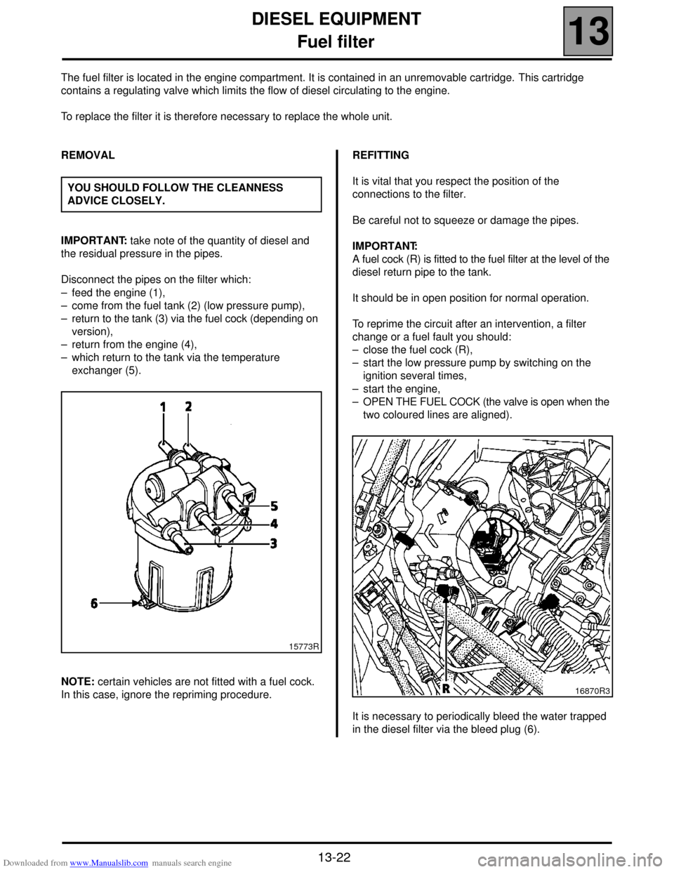
The fuel filter is located in the engine compartment. It is contained in an unremovable cartridge. This cartridge
contains a regulating valve which limits the flow of diesel circulating to the engine.
To replace the filter it is therefore necessary to replace the whole unit.
REMOVAL
IMPORTANT: take note of the quantity of diesel and
the residual pressure in the pipes.
Disconnect the pipes on the filter which:
– feed the engine (1),
– come from the fuel tank (2) (low pressure pump),
– return to the tank (3) via the fuel cock (depending on
version),
– return from the engine (4),
– which return to the tank via the temperature
exchanger (5).
NOTE: certain vehicles are not fitted with a fuel cock.
In this case, ignore the repriming procedure.REFITTING
It is vital that you respect the position of the
connections to the filter.
Be careful not to squeeze or damage the pipes.
IMPORTANT:
A fuel cock (R) is fitted to the fuel filter at the level of the
diesel return pipe to the tank.
It should be in open position for normal operation.
To reprime the circuit after an intervention, a filter
change or a fuel fault you should:
– close the fuel cock (R),
– start the low pressure pump by switching on the
ignition several times,
– start the engine,
– OPEN THE FUEL COCK (the valve is open when the
two coloured lines are aligned).
It is necessary to periodically bleed the water trapped
in the diesel filter via the bleed plug (6). YOU SHOULD FOLLOW THE CLEANNESS
ADVICE CLOSELY.
15773R
16870R3
Page 104 of 118
Downloaded from www.Manualslib.com manuals search engine COOLING SYSTEM
Diagram
19
19-2
Diagram
1 Engine
2 Radiator
3 "Hot" container with degassing after thermostat
4 Heater matrix
5 Thermostat mounting
6 Thermoplunger mounting (if fitted)7 3 mm ∅ restriction
8 6 mm ∅ restriction
9 Oil/water exchanger
10 Water pump
11 Thermostat
12 Bleed screw
The expansion bottle valve rating is 1.2 bar
(colour: brown).
Page 107 of 118

Downloaded from www.Manualslib.com manuals search engine COOLING SYSTEM
Water pump
19
19-5
Water pump
REMOVAL
Put the vehicle on a two post lift.
Disconnect the battery.
Remove the engine undertray.
Drain the cooling circuit through the lower radiator
hose.
Unclip the diesel filter and remove it.
Remove:
– the front right wheel along with the mudguard,
– the style cover,
– the accessories belt (see Section 07 "Accessories
belt tension"),
– the coolant pump and power assisted steering pump
pulleys,
– the water pump.Cleaning
It is very important not to scratch the gasket faces.
Use the Décapjoint product to dissolve any part of the
gasket which remains attached.
Wear gloves whilst carrying out the following
operation.
– Apply the product to the parts to be cleaned; wait
about ten minutes, then remove it using a wooden
spatula.
Do not allow this agent to drip on to the paintwork.
REFITTING
Refit:
– the water pump (fitted with a new gasket), tightening
the bolts to a torque of 1.7 daN.m,
– the accessories belt and tension it (see section 07
"Accessories belt tension").
Fill and bleed the cooling circuit, (see section 19
"Filling and Bleeding"). SPECIAL TOOLING REQUIRED
Mot. 1202 -01
Hose clip pliers
Mot. 1202 -02
Mot. 1448 Long nose pliers for hose clips
TIGHTENING TORQUES (in daN.m)
Water pump bolts 1.7