Page 2 of 118

Downloaded from www.Manualslib.com manuals search engine Contents
Page
07
10
11
12
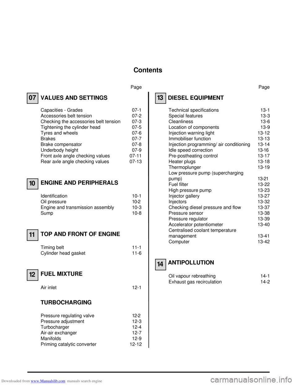
VALUES AND SETTINGS
Capacities - Grades 07-1
Accessories belt tension 07-2
Checking the accessories belt tension 07-3
Tightening the cylinder head 07-5
Tyres and wheels 07-6
Brakes 07-7
Brake compensator 07-8
Underbody height 07-9
Front axle angle checking values 07-11
Rear axle angle checking values 07-13
ENGINE AND PERIPHERALS
Identification 10-1
Oil pressure 10-2
Engine and transmission assembly 10-3
Sump 10-8
TOP AND FRONT OF ENGINE
Timing belt 11-1
Cylinder head gasket 11-6
FUEL MIXTURE
Air inlet 12-1
TURBOCHARGING
Pressure regulating valve 12-2
Pressure adjustment 12-3
Turbocharger 12-4
Air-air exchanger 12-7
Manifolds 12-9
Priming catalytic converter 12-12Page
13
14
DIESEL EQUIPMENT
Technical specifications 13-1
Special features 13-3
Cleanliness 13-6
Location of components 13-9
Injection warning light 13-12
Immobiliser function 13-13
Injection programming/ air conditioning 13-14
Idle speed correction13-16
Pre-postheating control 13-17
Heater plugs 13-18
Thermoplunger 13-19
Low pressure pump (supercharging
pump)13-21
Fuel filter 13-22
High pressure pump 13-23
Injector gallery 13-27
Injectors 13-32
Checking diesel pressure and flow 13-37
Pressure sensor 13-38
Pressure regulator 13-39
Accelerator potentiometer 13-40
Centralised coolant temperature
management 13-41
Computer 13-42
ANTIPOLLUTION
Oil vapour rebreathing 14-1
Exhaust gas recirculation 14-2
Page 12 of 118
Downloaded from www.Manualslib.com manuals search engine VALUES AND SETTINGS
Underbody height
07
07-9
Underbody height
The difference between the right-hand side and the left-hand side of the same axle of a vehicle must not exceed
5 mm, the driver's side always being higher.
Any alteration to the underbody height also requires adjustment of the brake compensator and of the headlights.Typeat the front
H1 - H2 = ... mm
± 7.5 mmat the rear
H4 - H5 = ... mm
± 7.5 mmDimension X (mm)
D and G
± 0.5 mm
BA05 104 22 496
JA05 102 27 512
98336R
Page 44 of 118

Downloaded from www.Manualslib.com manuals search engine TURBOCHARGING
Turbocharger
12
12-6
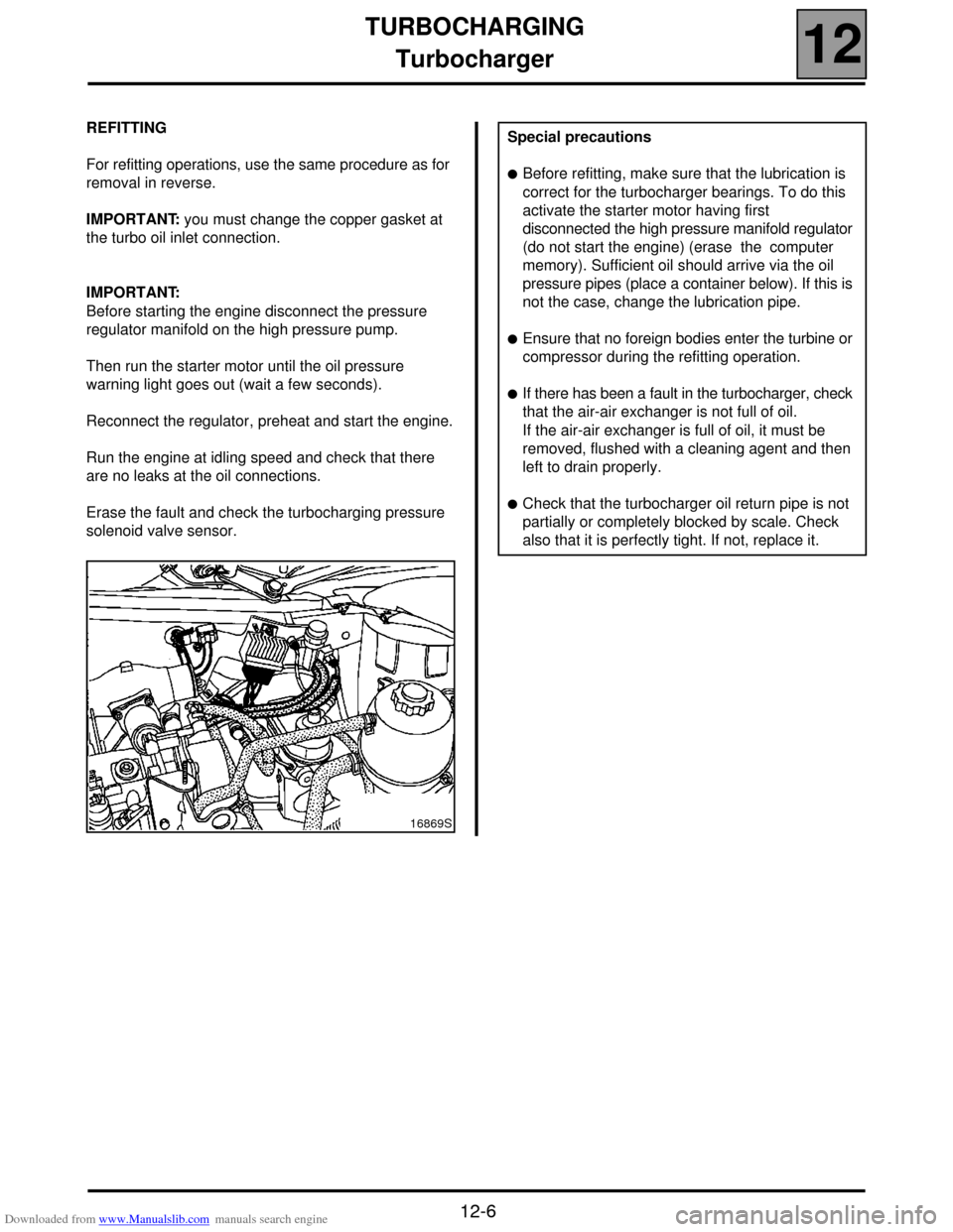
REFITTING
For refitting operations, use the same procedure as for
removal in reverse.
IMPORTANT: you must change the copper gasket at
the turbo oil inlet connection.
IMPORTANT:
Before starting the engine disconnect the pressure
regulator manifold on the high pressure pump.
Then run the starter motor until the oil pressure
warning light goes out (wait a few seconds).
Reconnect the regulator, preheat and start the engine.
Run the engine at idling speed and check that there
are no leaks at the oil connections.
Erase the fault and check the turbocharging pressure
solenoid valve sensor.
16869S
Special precautions
!Before refitting, make sure that the lubrication is
correct for the turbocharger bearings. To do this
activate the starter motor having first
disconnected the high pressure manifold regulator
(do not start the engine) (erase the computer
memory). Sufficient oil should arrive via the oil
pressure pipes (place a container below). If this is
not the case, change the lubrication pipe.
!Ensure that no foreign bodies enter the turbine or
compressor during the refitting operation.
!If there has been a fault in the turbocharger, check
that the air-air exchanger is not full of oil.
If the air-air exchanger is full of oil, it must be
removed, flushed with a cleaning agent and then
left to drain properly.
!Check that the turbocharger oil return pipe is not
partially or completely blocked by scale. Check
also that it is perfectly tight. If not, replace it.
Page 45 of 118
Downloaded from www.Manualslib.com manuals search engine TURBOCHARGING
Air-air exchanger
12
12-7
Air-air exchanger
REMOVAL
It is necessary to remove the bumper to access the air-
air exchanger.
To do this, remove:
– the two upper side mounting bolts (A) (torx 20) and
the lower side mounting bolt (B) (torx 20) from the
front section of the front wing inner protector,
– the three mounting clips (C),
– the mounting clip (D) and separate the front section
of the right and left wing protector.If the vehicle is fitted with fog lights.
Disconnect:
– the battery,
– the fog light wiring harness connector (E) located in
the front section of the left-hand front wheel arch.
Remove:
– the upper side mounting bolt (F) on the bumper (on
each side),
– the two front engine underbody mounting bolts,
98710R2
99184R
99147R
Page 63 of 118

Downloaded from www.Manualslib.com manuals search engine DIESEL EQUIPMENT
Injection warning light
13
13-12
Injection warning light
Vehicles using the high pressure diesel system are fitted with two injection warning lights used during the preheating
phase and in case of an injection fault (or engine overheating).
WARNING LIGHT PRINCIPLE
!When ignition is switched on, the preheating light is lit during the preheating phase and then goes out (see section
13 "Pre-postheating control").
!When there is a fault on the injection system the "fault" warning light lights up. These faults are:
– internal computer fault,
– engine speed fault (the vehicle doesn't start),
– main relay or low pressure fault (the vehicle doesn't start),
– injector fault,
–TDC sensor coherence fault and camshaft sensor,
– rail pressure sensor fault,
– rail pressure regulator fault,
– accelerator potentiometer fault,
– engine immobiliser fault,
– computer supply voltage fault,
– engine overheating.
NOTE: the OBD warning light (symbolised by an engine), visible when the ignition is switched on, is never visible
when the engine is running.
Page 64 of 118

Downloaded from www.Manualslib.com manuals search engine DIESEL EQUIPMENT
Immobiliser function
13
13-13
Immobiliser function
This vehicle is fitted with an engine immobiliser controlled by a random rolling code key recognition system.
REPLACING AN INJECTION COMPUTER
The injection computers are supplied without a code but they must all be programmed with one.
When the computer is replaced, the vehicle code must be programmed in and then a check must be made to ensure
that the immobiliser system is operational.
To do this, simply switch on the ignition for a few seconds without starting the engine then switch it of f. When the
ignition is off, the engine immobiliser function will be activated after approximately 10 seconds (red engine
immobiliser warning light flashes).
IMPORTANT:
With this engine immobiliser, the computer keeps its immobiliser code for life.
In addition, this system does not have a security code.
Consequently, it is forbidden to perform tests with computers borrowed from the stores or from another
vehicle which must then be returned.
It will no longer be possible to decode them.
Page 68 of 118
Downloaded from www.Manualslib.com manuals search engine DIESEL EQUIPMENT
Pre-postheating control
13
13-17
Pre-postheating control
The pre-postheating function is controlled by the preheating unit.
OPERATING PRINCIPLE FOR PRE-POST HEATING
1) "Preheating" on ignition
a) Variable preheating
The warning light lighting time and the
supply to heater plugs time depends on the
coolant temperature and the battery
voltage.
In all cases the injection warning light
lighting time cannot exceed 15 seconds.
b) Fixed preheating
After the warning light goes out the plugs
remain supplied for a fixed period of
10 seconds.2) Starting
The plugs remain supplied while the starter is
being activated.
3) "Postheating" while the engine is running
During this phase the plugs are supplied
continuously according to coolant temperature.
time (s)
Coolant
temperature °C For idling speed without
depression of the accelerator
pedal.
Page 92 of 118

Downloaded from www.Manualslib.com manuals search engine DIESEL EQUIPMENT
Coolant temperature management
13
13-41
Coolant temperature management
CCTM
This system allows the engine cooling fan to be
controlled by the injection computer. It consists of a
single coolant temperature sensor serving injection,
the engine cooling fan, the temperature indicator and
the instrument panel temperature warning light.OPERATION
The injection computer controls, as a function of the
coolant temperature:
– the injection system,
– the engine cooling fan relays:
!the fan is kept at a low speed if the coolant
temperature exceeds 99 ˚C and stops when the
temperature drops below 96 ˚C,
!the fan is kept at a high speed if the coolant
temperature exceeds 102 ˚C and stops when the
temperature drops below 99 ˚C,
!the fan can be controlled by the air conditioning.
For vehicles without air conditioning, only the low
speed engine cooling fan is operational.
COOLANT TEMPERATURE WARNING LIGHT
(shared with the injection fault warning light)
The warning light is controlled by the computer.
It is illuminated when the temperature exceeds 120 ˚C.
16179R1
244 Coolant temperature sensor (injection and
coolant temperature indication on the
instrument panel).
Three track sensor, two tracks for coolant
temperature information and one track for
indication on the instrument panel.