Page 37 of 118

Downloaded from www.Manualslib.com manuals search engine TOP AND FRONT OF ENGINE
Cylinder head gasket
11
11-11
CLEANING
It is very important not to scratch the gasket faces
of any aluminium component.
Use the Décapjoint product to dissolve any part of the
gasket which remains attached.
W ear gloves whilst carrying out the following
operation.
– Apply the product to the parts to be cleaned; wait
about ten minutes, then remove it using a wooden
spatula.
W e must draw your attention to the care which
must be taken during this operation, to prevent
any foreign bodies from being introduced into the
oil ways (ducts located in the cylinder block and in
the cylinder head).
CHECKING THE GASKET FACE
Check for gasket face bow using a straight edge and a
set of shims.
Maximum deformation: 0.05 mm.
No regrinding of the cylinder head is permitted.
Check the cylinder head for cracks.Checking piston protrusion
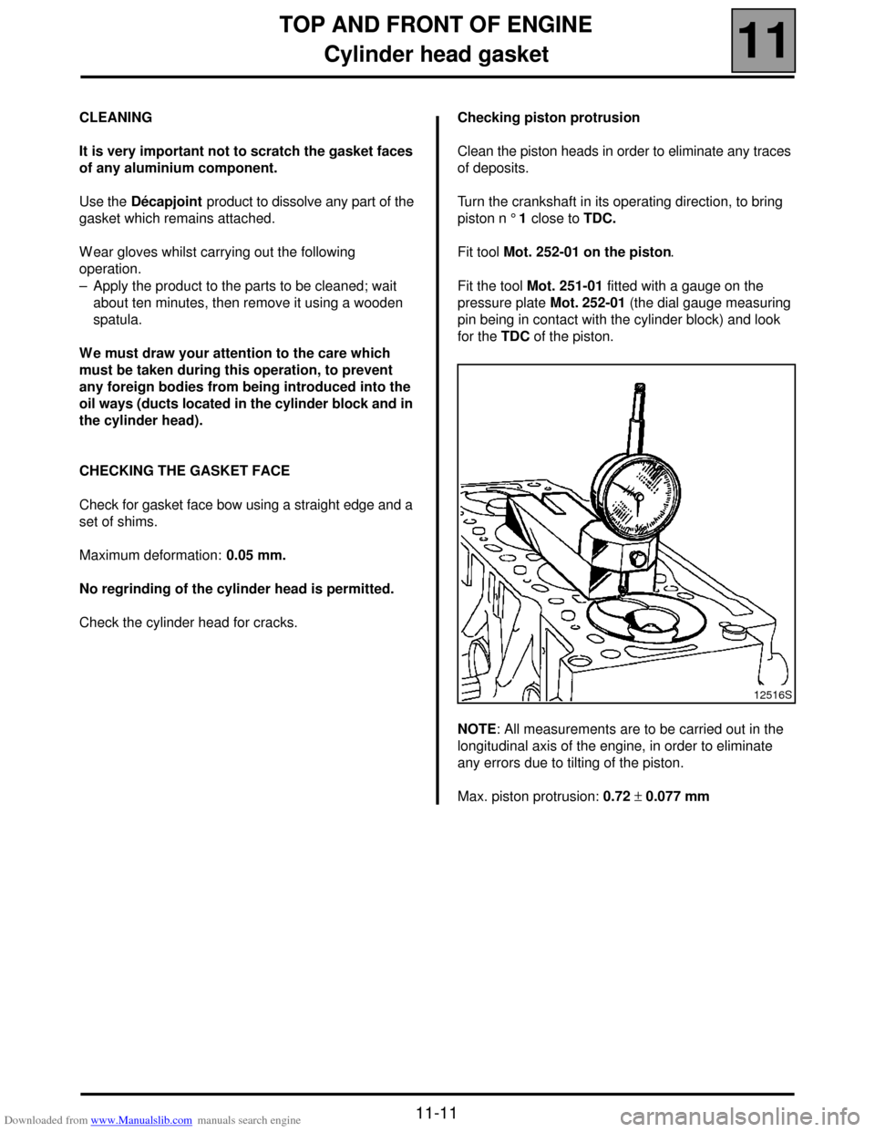
Clean the piston heads in order to eliminate any traces
of deposits.
Turn the crankshaft in its operating direction, to bring
piston n ° 1 close to TDC.
Fit tool Mot. 252-01 on the piston.
Fit the tool Mot. 251-01 fitted with a gauge on the
pressure plate Mot. 252-01 (the dial gauge measuring
pin being in contact with the cylinder block) and look
for the TDC of the piston.
NOTE: All measurements are to be carried out in the
longitudinal axis of the engine, in order to eliminate
any errors due to tilting of the piston.
Max. piston protrusion: 0.72 ± 0.077 mm
12516S
Page 42 of 118
Downloaded from www.Manualslib.com manuals search engine TURBOCHARGING
Turbocharger
12
12-4
Turbocharger
SPECIAL TOOLING REQUIRED
Elé. 1294 -01 Tool for removing windscreen
wiper arms
REMOVAL
NOTE: to slacken the turbocharger mounting nuts
more easily on the exhaust manifold, it is useful to
spray a releasing agent on the nuts when still hot, just
before removal.
Disconnect the battery.
Remove the engine cover.
From below
Remove:
– the engine undertray,
– the mounting stay (5),
– the two bolts fixing the turbo oil return pipe (7) to the
engine,
– the lower turbo mounting nut on the exhaust
manifold.
Disconnect the turbo pre-catalytic converter (6)
(priming catalytic converter). TIGHTENING TORQUES (in daN.m )
Turbo mounting nuts (1) 2.4
Oil inlet connection (4) 2.4
Oil inlet connection (3) 2.6
Oil return connection bolt (7) 1.2
Primer catalytic converter mounting bolt
to turbo (2) 2.4
16156R1
16155R1
Page 43 of 118
Downloaded from www.Manualslib.com manuals search engine TURBOCHARGING
Turbocharger
12
12-5
From above
Remove (for the Scénic):
– the windscreen wiper arms using tool Elé. 1294-01,
– the scuttle panel,
– the bulkhead panel,
Disconnect the flow meter and remove the air unit.Remove:
– the turbo oil inlet connection (4),
– the two air intake and outlet ducts connected to the
turbo,
– the two upper turbo mounting nuts on the manifold.
Disconnect the rubber hose (9) (connected to the
wastegate).
11020R
11036R2
12415R6
Page 44 of 118

Downloaded from www.Manualslib.com manuals search engine TURBOCHARGING
Turbocharger
12
12-6
REFITTING
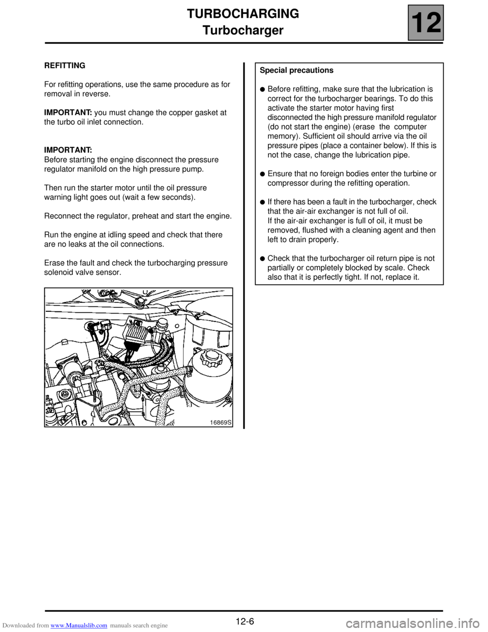
For refitting operations, use the same procedure as for
removal in reverse.
IMPORTANT: you must change the copper gasket at
the turbo oil inlet connection.
IMPORTANT:
Before starting the engine disconnect the pressure
regulator manifold on the high pressure pump.
Then run the starter motor until the oil pressure
warning light goes out (wait a few seconds).
Reconnect the regulator, preheat and start the engine.
Run the engine at idling speed and check that there
are no leaks at the oil connections.
Erase the fault and check the turbocharging pressure
solenoid valve sensor.
16869S
Special precautions
!Before refitting, make sure that the lubrication is
correct for the turbocharger bearings. To do this
activate the starter motor having first
disconnected the high pressure manifold regulator
(do not start the engine) (erase the computer
memory). Sufficient oil should arrive via the oil
pressure pipes (place a container below). If this is
not the case, change the lubrication pipe.
!Ensure that no foreign bodies enter the turbine or
compressor during the refitting operation.
!If there has been a fault in the turbocharger, check
that the air-air exchanger is not full of oil.
If the air-air exchanger is full of oil, it must be
removed, flushed with a cleaning agent and then
left to drain properly.
!Check that the turbocharger oil return pipe is not
partially or completely blocked by scale. Check
also that it is perfectly tight. If not, replace it.
Page 57 of 118

Downloaded from www.Manualslib.com manuals search engine DIESEL EQUIPMENT
Cleanliness
13
13-6
Cleanliness
CLEANLINESS INSTRUCTIONS WHICH MUST BE FOLLOWED WHEN WORKING ON THE HIGH PRESSURE
DIRECT INJECTION SYSTEM
Risks relating to contamination
The system is very sensitive to contamination. The risks caused by the introduction of pollution are:
– damage to or destruction of the high pressure injection system,
– seizing of a component or a component which is not sealed.
All after-sales operations must be performed under very good cleanliness conditions. This means that no impurities
(particles a few microns in size) have penetrated into the system during removal or into the circuits via the fuel
unions.
The cleanliness principle must be applied from the filter to the injectors.
WHAT ARE THE POLLUTING ELEMENTS?
The elements which pollute are:
– metal or plastic splinters,
– paint,
– fibres:
!of cardboard,
!of brushes,
!of paper,
!of clothing,
!of cloths.
– foreign bodies such as hair,
– ambient air,
– etc.
WARNING: it is impossible to clean the engine using a high pressure washer at the risk of damaging connections.
Also the moisture may collect in the connectors and cause electrical connection problems.
INSTRUCTIONS TO BE FOLLOWED BEFORE
ANY WORK IS CARRIED OUT ON THE INJECTION SYSTEM
!Ensure that you have plugs for the unions to be opened (bag of plugs sold by the Parts Department).
Plugs are to be used once only. After use, they must be thrown away (once used they are soiled and cleaning is
not sufficient to make them reusable).
Unused plugs must be thrown away.
!Ensure that you have the resealable plastic bags for storing removed parts. There is less risk of parts stored in this
way being subjected to impurities. The bags can be used only once, and once used they must be thrown away.
!Ensure that lint-free cleaning wipes are available (cloths with SODICAM part numbers). The use of conventional
cloth or paper is prohibited. In fact, these create lint and may contaminate the system's fuel circuit. A lint-free
cloth should only be used once.
Page 95 of 118
Downloaded from www.Manualslib.com manuals search engine ANTIPOLLUTION
Oil vapour rebreathing
14
14-1
114ANTIPOLLUTION
Oil vapour rebreathing
CIRCUIT DIAGRAM
1Engine
2Oil separator
3Air filter unit
4Inlet manifold
CHECKING
To ensure the correct operation of the anti-pollution
system, the oil vapour rebreathing circuit must be kept
clean and in good condition.AOil vapour rebreathing pipe for the bottom of engine
BOil vapour rebreathing pipe for the top of engine
COil separator
DOil vapour rebreathing pipe linked to the intake
pipes
13042R
DI1322
Page 102 of 118
Downloaded from www.Manualslib.com manuals search engine STARTING - CHARGING
Starter
16
16-5
REMOVAL
Put the vehicle on a 2 post lift.
Disconnect the battery.
Remove (for the Scénic):
– the front right hand grille as well as the mounting
bolts of the left hand grille,
– the closure panel of the scuttle,Remove (all types):
– the turbocharging air ducts between the exchanger
and the engine,
– the pre-catalytic converter mountings to the turbo.
Loosen the exhaust pipe clamp mounting.
Remove:
– the pre-catalytic converter stay (1),
– the catalytic converter mountings on the precatalytic
converter and remove this by moving the engine
towards the cooling system,
– the oil return pipe (8),
– the starter electrical connections.
– the starter mountings,
– the starter motor.
REFITTING
To remove, proceed in the reverse order.
Check the presence of the starter motor centring
dowel.
11020R
11036R2
16155R
Page 104 of 118
Downloaded from www.Manualslib.com manuals search engine COOLING SYSTEM
Diagram
19
19-2
Diagram
1 Engine
2 Radiator
3 "Hot" container with degassing after thermostat
4 Heater matrix
5 Thermostat mounting
6 Thermoplunger mounting (if fitted)7 3 mm ∅ restriction
8 6 mm ∅ restriction
9 Oil/water exchanger
10 Water pump
11 Thermostat
12 Bleed screw
The expansion bottle valve rating is 1.2 bar
(colour: brown).