Page 25 of 52
Downloaded from www.Manualslib.com manuals search engine FUEL MIXTURE
Air intake
12
12-3
FUEL MIXTURE
Air intake
AIR INTAKE CIRCUIT DIAGRAM
1Air-air exchanger
2Air filter
3Damper unit
4Inlet manifold
5Turbocharger
6Air inlet
Page 26 of 52
Downloaded from www.Manualslib.com manuals search engine FUEL MIXTURE
Air intake
12
12-4
DAMPER UNIT
This unit, controlled by the injection computer, comprises a throttle placed in
the air inlet flow which closes when the ignition is switched of f to ensure that
the engine stops cleanly.
It also includes the exhaust gas recirculation solenoid valve.TIGHTENING TORQUES (in daN.m)
Clip nuts 5.5
Page 27 of 52
Downloaded from www.Manualslib.com manuals search engine FUEL MIXTURE
Air intake
12
12-5
REMOVAL
Put the vehicle on a two post lift.
Disconnect the battery.
Remove:
–the lower engine cover,
–the air exchanger/damper unit pipe after
disconnecting the electrics.
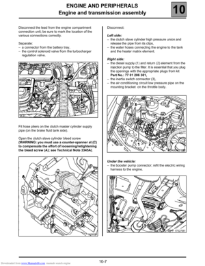
Place hose pliers on the oil tank/power assisted
steering pump return pipe and disconnect the pump.
Separate the power steering reservoir without
disconnecting the pump and move it on the side
member.Remove:
–the turbocharger/exchanger air pipe mounting bolts
from the cylinder head,
–the stiffening bracket (1) between the damper unit
and the power assisted steering pump mounting,
–the exhaust gas recirculation pipe (2) and the seals.
Plan for the replacement of the pipe and the seals
when refitting.
Disconnect the exhaust gas recirculation control
solenoid valve connector.
15853M1
Page 28 of 52
Downloaded from www.Manualslib.com manuals search engine FUEL MIXTURE
Air intake
12
12-6
Remove:
–the mounting bolt from the low pressure air
conditioning pipe bracket (3),
–the mounting bolts (4) from the throttle body on the
engine housing. Use a 13 mm dowel, a cardan joint
and small extension. If necessary, remove the pipes
to access the bolts.
WARNING: avoid loosening the four self-tapping bolts
(A) which attach the top to the unit body.Remove the connection pipe (5) between the throttle
body and the inlet manifold,
If necessary, unclip the electrical wiring in front of the
damper unit to ease the downwards release of this
unit.
REFITTING
Proceed in the reverse order from removal.
Tighten the mounting clips to 5.5 daN.m.
Check that there are no stored faults using a fault
finding tool. Erase them if necessary.
Page 29 of 52
Downloaded from www.Manualslib.com manuals search engine FUEL MIXTURE
Exhaust manifold
12
12-7
Exhaust manifold
REMOVAL
Removal of the exhaust manifold requires removal of the engine and
transmission assembly (see section 10 "Removing/refitting engine and
transmission assembly"), and the removal of the turbocharger (see
section 12 "Removing/refitting turbocharger").
REFITTING
Refit the manifold bolts in the order recommended above.
Refitting is the reverse of removal.TIGHTENING TORQUES (in daN.m)
Manifold mounting nut 0.8±0.2
Manifold mounting nut 2.7±0.4
EGR valve mounting bolt 1.5
Turbocharger clamp mounting bolt 2.7
Page 30 of 52
Downloaded from www.Manualslib.com manuals search engine FUEL MIXTURE
Inlet manifold
12
12-8
Inlet manifold
REMOVAL
The removal of the inlet manifold/cylinder head cover
requires the removal of the injectors and injection
harnesses. (See section 13 "Removing/refitting the
high pressure injection section").
Insert the mounting tool Mot. 1390 under the engine
and transmission assembly, positioning the right-hand
pads only beneath the engine. Lower the two unused
left-hand pads.Remove the right-hand suspended engine mounting
cover.
Undo the two clips on the connection hose (1)
between the inlet manifold and the damper unit.
Remove the pad (2). SPECIAL TOOLING REQUIRED
Mot. 1390 Engine and transmission
assembly mounting tool
TIGHTENING TORQUES (in daN.m)
Heater plugs 1.1
Manifold mounting stud 1
"Common-Rail" high pressure unions 2.5
15855M2
Page 31 of 52
Downloaded from www.Manualslib.com manuals search engine FUEL MIXTURE
Inlet manifold
12
12-9
Remove the manifold mounting bolts and then remove the manifold.
REFITTING
IMPORTANT: note the rubber seal on the inlet tubes;
if necessary, seal this in its casing with some grease.
Bring all the cylinder head cover bolts into contact.
Tighten to 1.2 daN.m observing the tightening order
for the cylinder head cover bolts.
It is essential that you observe the order of tightening
and the torques recommended for refitting the
suspended mounting and the high pressure injection
section (see sections 13 and 19).
To refit, proceed in the reverse order to removal.
17934R
Page 32 of 52
Downloaded from www.Manualslib.com manuals search engine STARTING - CHARGING
Alternator
16
116STARTING - CHARGING
Alternator
IDENTIFICATION
CHECKING
After 15 minutes warming up at a voltage of 13.5 volts.Type Engine Alternator Current
JE0 K
JE0 SG9T VALEO SG 12 125 A
Rpm Amps
1500 26 A
4000 94 A
6000 105 A
16-1


,
–the mounting bolts (4")


