Page 7 of 52

Downloaded from www.Manualslib.com manuals search engine ENGINE AND PERIPHERALS
Engine and transmission assembly
10
10-3
Engine and transmission assembly
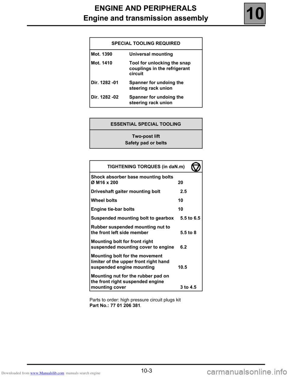
Parts to order: high pressure circuit plugs kit
Part No.: 77 01 206 381. SPECIAL TOOLING REQUIRED
Mot. 1390 Universal mounting
Mot. 1410 Tool for unlocking the snap
couplings in the refrigerant
circuit
Dir. 1282 -01 Spanner for undoing the
steering rack union
Dir. 1282 -02 Spanner for undoing the
steering rack union
ESSENTIAL SPECIAL TOOLING
Two-post lift
Safety pad or belts
TIGHTENING TORQUES (in daN.m)
Shock absorber base mounting bolts
Ø M16 x 200 20
Driveshaft gaiter mounting bolt 2.5
Wheel bolts 10
Engine tie-bar bolts 10
Suspended mounting bolt to gearbox 5.5 to 6.5
Rubber suspended mounting nut to
the front left side member 5.5 to 8
Mounting bolt for front right
suspended mounting cover to engine 6.2
Mounting bolt for the movement
limiter of the upper front right hand
suspended engine mounting 10.5
Mounting nut for the rubber pad on
the front right suspended engine
mounting cover 3 to 4.5
Page 15 of 52
Downloaded from www.Manualslib.com manuals search engine TOP AND FRONT OF ENGINE
Accessories belt
11
111TOP AND FRONT OF ENGINE
Accessories belt
REMOVAL
Put the vehicle on a two post lift.
Disconnect the battery.
Remove:
–the front right wheel,
–the front right wheel arch,
–the lower engine cover.
Using a ring spanner, turn the tensioner axle clockwise to release the belt and
insert a tool (e.g.: Allen key) to lock the tensioner in this position.
REFITTING
Replace the accessories belt.
NOTE: never refit a belt once it has been removed, but replace it.
Refitting is the reverse of removal.TIGHTENING TORQUES (in daN.m)
Wheel bolts 10
15850-8S
11 - 1
Page 16 of 52
Downloaded from www.Manualslib.com manuals search engine TOP AND FRONT OF ENGINE
Timing belt
11
11 - 2
Timing belt
REMOVAL
Disconnect the battery.
If necessary, place the vehicle on a two-post lift.
Remove the right-hand side member soundproofing.
Remove the travel limiter linkage.
Turn the steering to full right-hand lock.
Remove the front right wheel arch cover. Adjust the engine cylinder n˚ 1 to top dead centre
(marking (1) on the crankshaft pulley) and pin the
crankshaft after removing the cap (A). SPECIAL TOOLING REQUIRED
Mot. 1390 Engine and transmission
assembly mounting tool
Mot. 1536 TDC setting pin
Mot. 1534 Inlet camshaft timing/locking
tool
Mot. 1537 Exhaust camshaft timing/
locking tool
TIGHTENING TORQUES (in daN.m)
Tensioner nut 2.6
Fixed roller nut 3.3
Timing cover bolt 1
Suspended mounting limiter bolt 10.5
Suspended mounting cover bolt 6.2
Wheel bolts 10
15854M1
Page 18 of 52
Downloaded from www.Manualslib.com manuals search engine TOP AND FRONT OF ENGINE
Timing belt
11
11 - 4
Fit the camshaft locking tools and tighten them
carefully to the cylinder head.
Release the tension in the timing belt by undoing the
timing tension wheel bolt.Remove:
–the exhaust camshaft sprocket by undoing the three
mounting bolts on the sprocket on the hub),
–the timing belt.
Remove tool Mot. 1537.
Remove the gear tensioner.
17943M1
15850M1
17553-2M
Page 19 of 52

Downloaded from www.Manualslib.com manuals search engine TOP AND FRONT OF ENGINE
Timing belt
11
11 - 5
–the pulley; remove the nut and take the pulley out
without removing the stud.
REFITTING
Fit:
–the pulley,
–the automatic tension wheel without tightening it and
position the groove (7) of the tension wheel correctly
in the pin,
–the three bolts at the centre of the inlet camshaft
sprocket holes (this must be free),
–the exhaust camshaft timing tool Mot. 1537.
Check that the crankshaft is at top dead centre.
Fit the timing belt at the same time as the exhaust
camshaft sprocket, and position the sprocket mounting
bolts at the centre of the holes.
Operation of the exhaust camshaft timing/locking tool
repeater: mobile mark (1) on the tension wheel pushes
the repeater (2) to the lower section (3). The upper
section has two edges (4) and (5) which, repeat the
position of the tension wheel index by aligning with the
edge (6) of the fixed section of the tool.Adjust the position of the tension wheel (by pivoting
the tension wheel eccentric anticlockwise) plus
approximately 5˚ by aligning sections (5) and (6).
16026M
17551M
Page 20 of 52
Downloaded from www.Manualslib.com manuals search engine TOP AND FRONT OF ENGINE
Timing belt
11
11 - 6
Tighten:
–the tension wheel bolt (8),
–the camshaft timing sprocket bolts (9) to a torque of
1 daN.m.
Remove the camshaft timing tools Mot. 1534 and
Mot. 1537 and the TDC pin Mot. 1536.
Rotate the crankshaft through two revolutions in a
clockwise direction (timing side).
Pin the crankshaft to top dead centre (the top dead
centre mark on the crankshaft accessories pulley must
be in the vertical axis of the engine).
Fit the camshaft timing tools Mot. 1534 and
Mot. 1537.
Check that the tab of Mot. 1537 moves vertically
without constraint.
Undo the camshaft timing sprocket bolts by a
maximum of one turn. Checking the timing and the tension
Undo the tension wheel bolt (8) while holding the
eccentric with a 6 mm Allen key.
Pivot the tension wheel eccentric clockwise, until the
surface (10) of the tab (11) is aligned with the
upper surface (12) of tool 1537.
Page 24 of 52

Downloaded from www.Manualslib.com manuals search engine TURBOCHARGING
Turbocharger
12
12-2
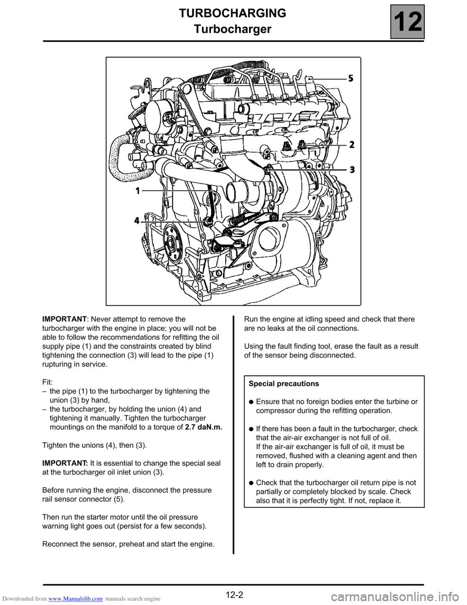
IMPORTANT: Never attempt to remove the
turbocharger with the engine in place; you will not be
able to follow the recommendations for refitting the oil
supply pipe (1) and the constraints created by blind
tightening the connection (3) will lead to the pipe (1)
rupturing in service.
Fit:
–the pipe (1) to the turbocharger by tightening the
union (3) by hand,
–the turbocharger, by holding the union (4) and
tightening it manually. Tighten the turbocharger
mountings on the manifold to a torque of 2.7 daN.m.
Tighten the unions (4), then (3).
IMPORTANT: It is essential to change the special seal
at the turbocharger oil inlet union (3).
Before running the engine, disconnect the pressure
rail sensor connector (5).
Then run the starter motor until the oil pressure
warning light goes out (persist for a few seconds).
Reconnect the sensor, preheat and start the engine.Run the engine at idling speed and check that there
are no leaks at the oil connections.
Using the fault finding tool, erase the fault as a result
of the sensor being disconnected.
Special precautions
●Ensure that no foreign bodies enter the turbine or
compressor during the refitting operation.
●If there has been a fault in the turbocharger, check
that the air-air exchanger is not full of oil.
If the air-air exchanger is full of oil, it must be
removed, flushed with a cleaning agent and then
left to drain properly.
●Check that the turbocharger oil return pipe is not
partially or completely blocked by scale. Check
also that it is perfectly tight. If not, replace it.
Page 39 of 52
Downloaded from www.Manualslib.com manuals search engine COOLING SYSTEM
Coolant pump
19
19-3
Coolant pump
REMOVAL
Put the vehicle on a 2 post lift.
Disconnect the battery.
Bleed the engine cooling circuit and engine oil; do not
refit the oil drain plug.
Remove:
–the front right wheel,
–the right-hand wheel arch cover.
Remove the four mounting bolts of the coolant pump
cover.
Lock the crankshaft using a screwdriver in the starter
crown.
Remove the 30 hub lock nut from the coolant pump.Remove the coolant pump sprocket using the
U 14 L FACOM hub extractor
REFITTING
Replace the coolant pump.
WARNING: the rest of the coolant will drop into the
engine housing.
Ensure that the mating surface on the pump is clean
and that the coolant escapes from the engine housing
(oil change).
Refitting is the reverse of removal.
ESSENTIAL SPECIAL TOOLING
FACOM U 14 L sprocket extractor
14572-1S
14572S
18001M