Page 8 of 52
Downloaded from www.Manualslib.com manuals search engine ENGINE AND PERIPHERALS
Engine and transmission assembly
10
10-4
Place the vehicle on a two-post lift (fit the safety belts).
Disconnect and remove the battery.
Drain the refrigerant circuit (if fitted) using the filling
station.
Remove:
–the engine undertray,
–the front wheels,
–the front right and left undertrays at the end of the
wheel arches,
–the wheel arch protectors,
–the front bumper,
–the side driveshafts (see section 29 of Workshop
Repair Manual 315 "Remove and refit side
driveshafts").
Open the degassing tank.
Drain the power assisted steering circuit:
–by the low pressure hoses on the cooler,
–by disconnecting the power assisted steering high
pressure pipe (lower pipe) from the steering rack
(tool Dir. 1282-01). Take care to prevent escape.Drain the cooling circuit through the lower radiator
hose.
Remove the air filter unit.
Page 11 of 52

Downloaded from www.Manualslib.com manuals search engine ENGINE AND PERIPHERALS
Engine and transmission assembly
10
10-7
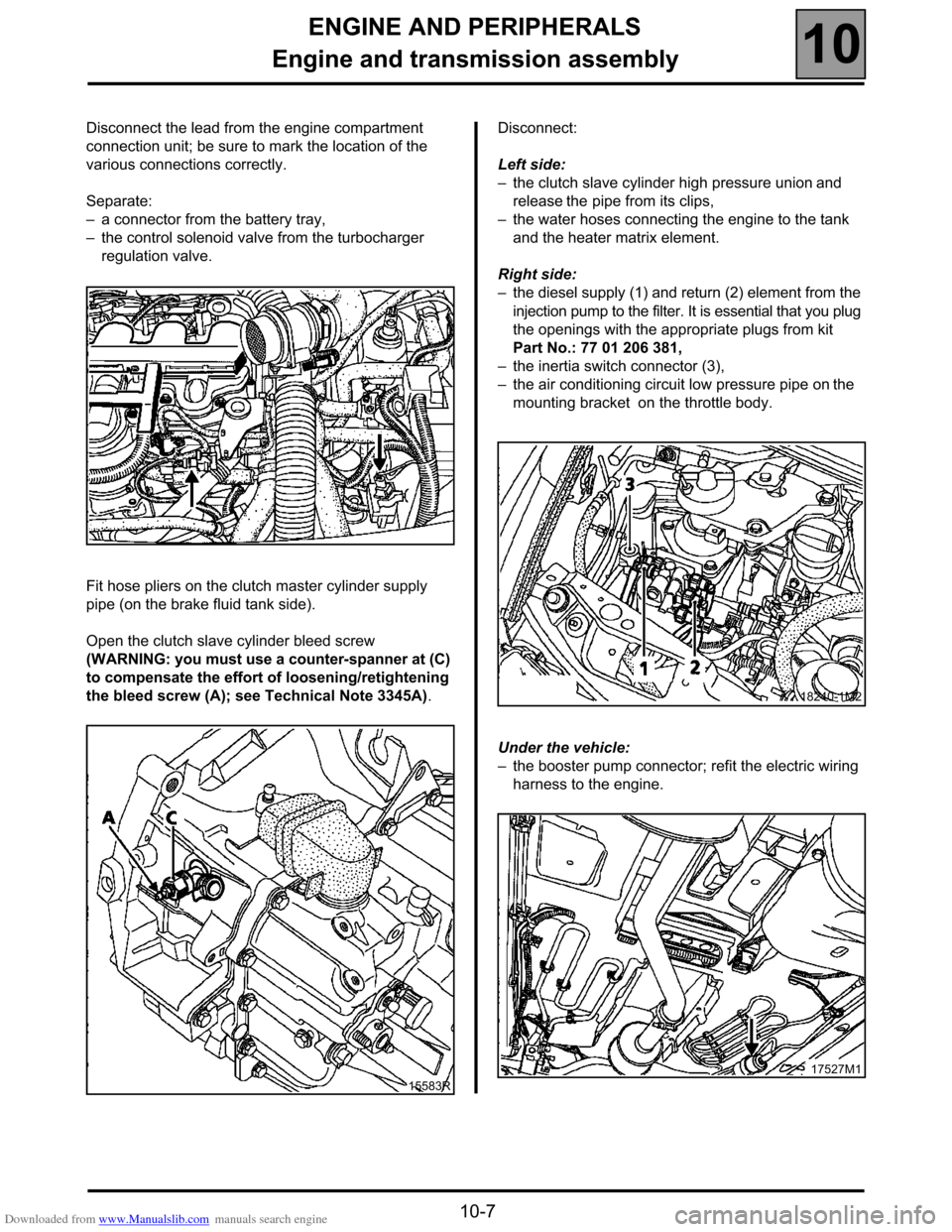
Disconnect the lead from the engine compartment
connection unit; be sure to mark the location of the
various connections correctly.
Separate:
–a connector from the battery tray,
–the control solenoid valve from the turbocharger
regulation valve.
Fit hose pliers on the clutch master cylinder supply
pipe (on the brake fluid tank side).
Open the clutch slave cylinder bleed screw
(WARNING: you must use a counter-spanner at (C)
to compensate the effort of loosening/retightening
the bleed screw (A); see Technical Note 3345A).Disconnect:
Left side:
–the clutch slave cylinder high pressure union and
release the pipe from its clips,
–the water hoses connecting the engine to the tank
and the heater matrix element.
Right side:
–the diesel supply (1) and return (2) element from the
injection pump to the filter. It is essential that you plug
the openings with the appropriate plugs from kit
Part No.: 77 01 206 381,
–the inertia switch connector (3),
–the air conditioning circuit low pressure pipe on the
mounting bracket on the throttle body.
Under the vehicle:
–the booster pump connector; refit the electric wiring
harness to the engine.
15583R
18240-1M2
17527M1
Page 25 of 52
Downloaded from www.Manualslib.com manuals search engine FUEL MIXTURE
Air intake
12
12-3
FUEL MIXTURE
Air intake
AIR INTAKE CIRCUIT DIAGRAM
1Air-air exchanger
2Air filter
3Damper unit
4Inlet manifold
5Turbocharger
6Air inlet
Page 36 of 52
Downloaded from www.Manualslib.com manuals search engine STARTING - CHARGING
Starter
16
16-5
REMOVAL
Put the vehicle on a 2 post lift.
Disconnect the battery.
Remove:
–the lower engine cover,
–the air exchanger/throttle body unit pipe after
disconnecting it,
–the dipstick,
–the three starter mounting bolts,–the oil filter unit bracket.
Release the filter bracket to the side, without
disconnecting it.
Disconnect the starter electrical connections.
Remove:
–the dipstick well,
–the starter motor.
REFITTING
To refit, proceed in the reverse order to removal.
17524M1
16028M
Page 47 of 52
Downloaded from www.Manualslib.com manuals search engine HEATING
Additional heating
61
61-2
DIAGRAM OF THE D3WZ HEATER
1Air blower turbine
2Electric motor
3Heat exchanger
4Combustion chamber
5Spark plug
6Flame detector
7Temperature sensor
8Overheating switch
9Control unit
10 Combustion air intake tube
11 Burnt gas exhaust pipe
12 Dosing pump 13 Fuel filter
14 Main fuse
15 Interface
ACombustion air inlet
BExhaust gas outlet
CVehicle fuel circuit
DCoolant inlet (thermoplunger outlet)
ECoolant outlet (towards the heater matrix)
Page 51 of 52

Downloaded from www.Manualslib.com manuals search engine HEATING
Additional heating
61
61-6
MAINTENANCE
The principal maintenance operations on this
assembly are:
–replacing the ignition spark plug (5),
–cleaning the filter at the pump inlet (13) (see
page 61-2).
REMOVING - REFITTING COMPONENTS
FUEL PUMP INLET FILTER (13)
Remove the front bumper.
Rotate the pump (12) (see page 61-2) if it turns and
loosen the union covering the filter (13). Clean or
replace the filter if there is a combustion problem.
IGNITION SPARK PLUG
Disconnect and remove the heater without draining the
cooling circuit (use pliers Mot. 453-01).
Remove:
–the turbine cover (1),
–the control unit (9) and the cap (16),
–the spark plug (5) after disconnecting it.
FLAME DETECTOR
Disconnect and remove the heater without draining the
cooling circuit (use pliers Mot. 453-01).
Remove:
–the turbine cover (1),
–the control unit (9) and the cap (16).
Disconnect the flame connector by pulling the flat
terminals from the connector.
Remove the flame detector.
(WARNING: fragile part)COMBUSTION CHAMBER (4) AND EXCHANGER (3)
Remove:
–the flame detector and spark plug,
–the wiring harness fitted on the overheating
detector (8) and the temperature sensor (7),
–the turbine support (1).
Remove the combustion chamber (4) and the
exchanger (3) if necessary.
FAULT FINDING
In case of a fault, check:
–if there is fuel in the tank,
–if the fuses are intact
–if the pipes, connections and electrical unions are
intact,
–if the combustion air ducts or exhaust gas ducts are
blocked (unblock them if necessary).
In the even of combustion with the production of soot,
check:
–if the combustion air ducts or exhaust gas ducts are
blocked (unblock them if necessary),
–if there is a deposit in the exchanger (3) or the
combustion chamber (4); clean these if necessary,
–if the dosing pump flow is correct;
To do this:
●remove the bumper,
●disconnect the electric pump inlet fuel pipe (12),
from the side opposite the fuel filter (13),
●connect a pipe to the electric pump so that the flow
can be collected in a glass at the same height as
the heater,
●start the heater (if necessary, bridge the
temperature sensor located in front of the battery
screen). After approximately 40 seconds, the fuel
arrives and begins to bleed the circuit. Switch off
the ignition. Empty the glass and start again,
collecting the stabilised flow for approximately
30 seconds. Switch off the heater and measure the
quantity of fuel collected.
Normal flow: between 6.8 cm
3 and 7.8 cm3 for
90 seconds of operation.