2000 NISSAN SENTRA clock
[x] Cancel search: clockPage 118 of 240

In order for the steering wheel to be locked,
it must be turned about 1/8 of a turn clock-
wise from the straight up position.
To lock the steering wheel, turn the key
to the LOCK position. Remove the key.
To unlock the steering wheel, insert the
key and turn it gently while rotating the
steering wheel slightly right and left.
WARNING
Never remove or turn the key to the
LOCK position while driving. The steer-
ing wheel will lock. This may cause the
driver to lose control of the vehicle and
could result in serious vehicle damage
or personal injury.
MANUAL TRANSMISSION
The ignition switch includes an anti-theft
steering lock device.
The key can be removed only when the
ignition switch is in the LOCK position.
On manual transmission models, to turn
the ignition key to LOCK from ACC or ON,
push in the key, then turn the key to LOCK.
In order for the steering wheel to be locked,
it must be turned about 1/8 of a turn clock-
wise from the straight up position.To lock the steering wheel, turn the key
to the LOCK position. Remove the key.
To unlock the steering wheel, insert the
key and turn it gently while rotating the
steering wheel slightly right and left.
WARNING
Never remove or turn the key to the
LOCK position while driving. The steer-
ing wheel will lock. This may cause the
driver to lose control of the vehicle and
could result in serious vehicle damage
or personal injury.
KEY POSITIONS
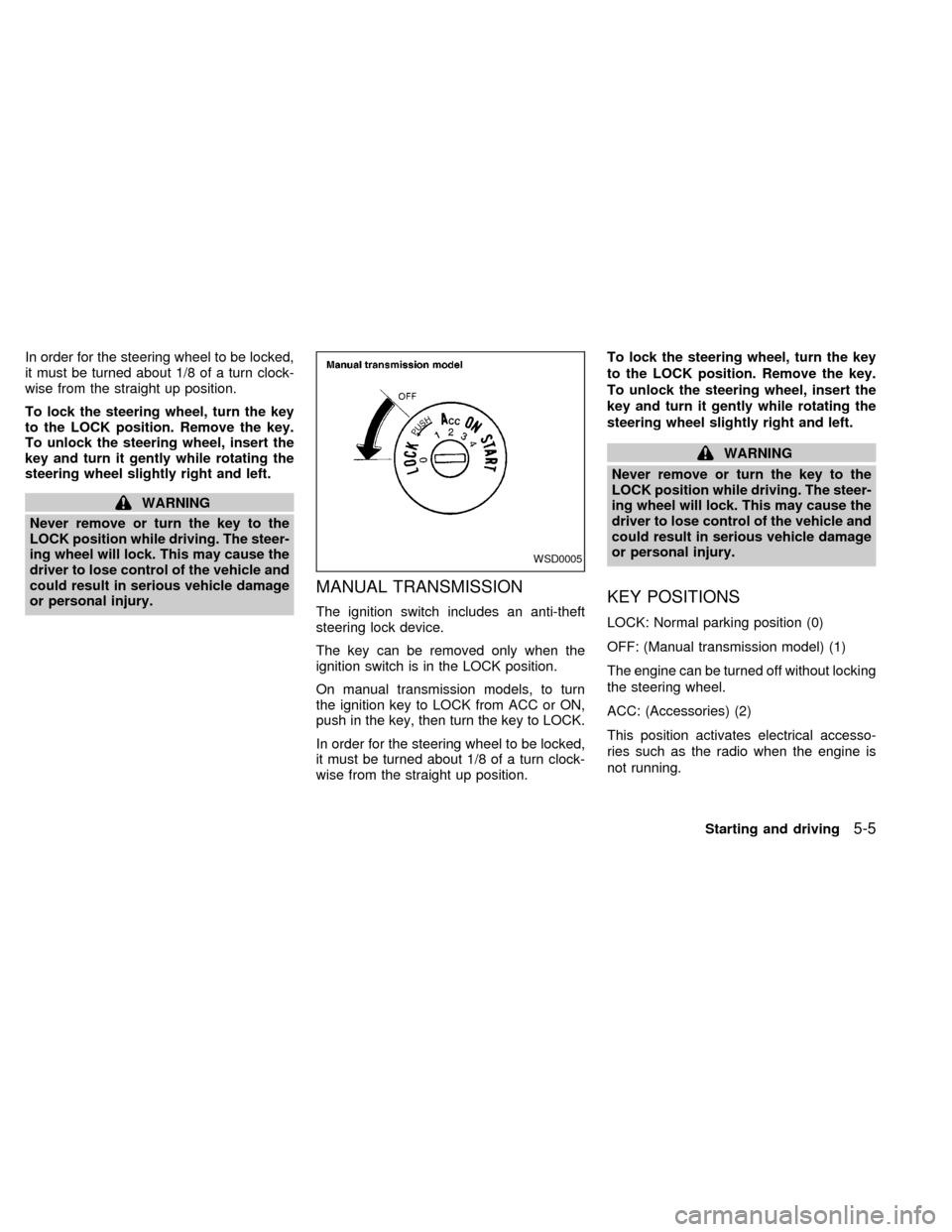
LOCK: Normal parking position (0)
OFF: (Manual transmission model) (1)
The engine can be turned off without locking
the steering wheel.
ACC: (Accessories) (2)
This position activates electrical accesso-
ries such as the radio when the engine is
not running.
WSD0005
Starting and driving5-5
ZX
Page 119 of 240

ON: Normal operating position (3)
This position turns on the ignition system
and the electrical accessories.
START: (4)
This position activates the starter motor,
which starts the engine.
NISSAN VEHICLE IMMOBILIZER
SYSTEM (NVIS) (if so equipped)
The Nissan Vehicle Immobilizer System
(NVIS) will not allow the engine to start
without the use of a registered NVIS key.
If the engine fails to start using a registered
NVIS key, it may be due to interference
caused by another NVIS key, an automated
toll road device or automated payment de-
vice on the key ring. Restart the engine
using the following procedures:
1. Leave the ignition switch in the ON posi-
tion for approximately 5 seconds.
2. Turn the ignition switch to the OFF or
LOCK position and wait approximately 5
seconds.
3. Repeat step 1 and 2 again.
4. Restart the engine while holding the de-
vice (which may have caused the inter-ference) separate from the registered
NVIS key.
If this procedure allows the engine to start,
NISSAN recommends placing the regis-
tered NVIS key on a separate key ring to
avoid interference from other devices.cMake sure the area around the vehicle is
clear.
cMaintenance items listed here should be
checked periodically, for example, each
time you check engine oil.
cCheck that all windows and lights are
clean.
cVisually inspect tires for their appearance
and condition. Also check tires for proper
inflation.
cLock all doors.
cPosition seat and adjust head restraints.
cAdjust inside and outside mirrors.
cFasten seat belts and ask all passengers
to do likewise.
c
Check the operation of warning lights
when key is turned to the ON (3) position.
See ``Warning/indicator lights and chimes''
in the ``Instrument and controls'' section.
BEFORE STARTING THE
ENGINE
5-6Starting and driving
ZX
Page 138 of 240

Getting the spare tire and tools
1. Open the trunk. Lift the trunk floor carpet-
ing and spare tire cover. Remove the tool
bag (which contains the jack rod and
wheel nut wrench) and the spare tire. If
necessary, use the flat end of the jack
rod as shown to loosen the spare tire
hold-down bolt.2. To remove the jack, turn the jack screw
counterclockwise. Use the tapered end
of the jack rod to loosen the jack from its
storage position.
WCE0012WCE0009
In case of emergency6-3
ZX
Page 141 of 240

cNever jack up the vehicle more than
necessary.
cNever use blocks on or under the
jack.
cDo not start or run engine while
vehicle is on the jack. It may cause
the vehicle to move.
cDo not allow passengers to stay in
the vehicle while it is on the jack.cNever run the engine with a wheel off
the ground. It may cause the vehicle
to move.
Carefully read the caution label attached
to the jack body and the following in-
structions.
1. Loosen each wheel nut one or two turns
by turning counterclockwise with the
wheel nut wrench.Do not remove the
wheel nuts until the tire is off the
ground.
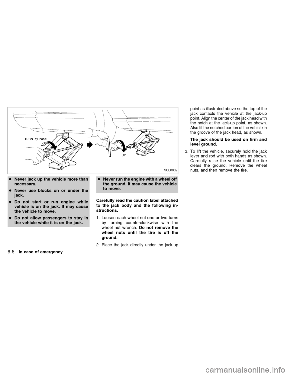
2.
Place the jack directly under the jack-uppoint as illustrated above so the top of the
jack contacts the vehicle at the jack-up
point. Align the center of the jack head with
the notch at the jack-up point, as shown.
Also fit the notched portion of the vehicle in
the groove of the jack head, as shown.
The jack should be used on firm and
level ground.
3.
To lift the vehicle, securely hold the jack
lever and rod with both hands as shown.
Carefully raise the vehicle until the tire
clears the ground. Remove the wheel
nuts, and then remove the tire.
SCE0002
6-6In case of emergency
ZX
Page 143 of 240

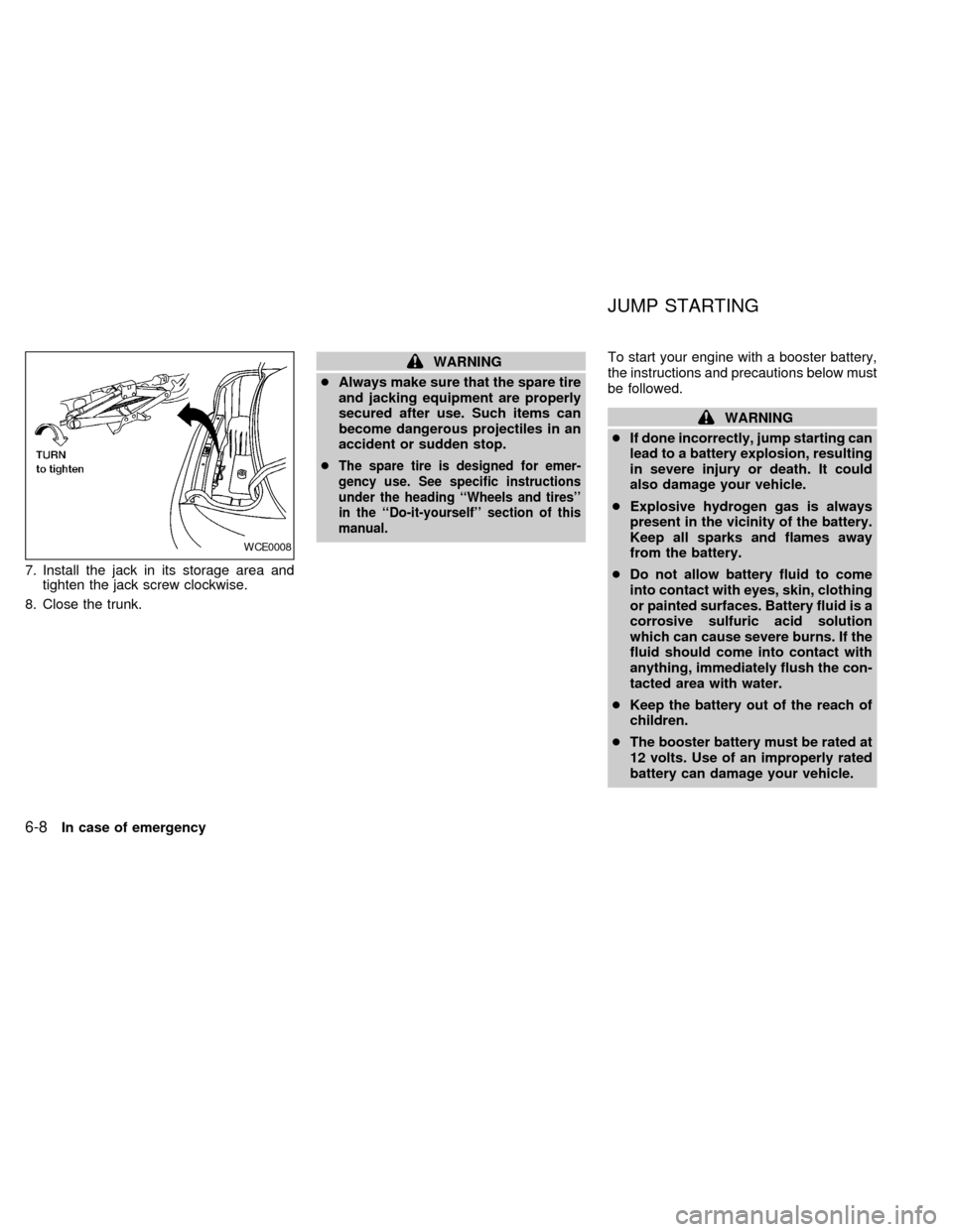
7. Install the jack in its storage area and
tighten the jack screw clockwise.
8. Close the trunk.
WARNING
cAlways make sure that the spare tire
and jacking equipment are properly
secured after use. Such items can
become dangerous projectiles in an
accident or sudden stop.
c
The spare tire is designed for emer-
gency use. See specific instructions
under the heading ``Wheels and tires''
in the ``Do-it-yourself'' section of this
manual.
To start your engine with a booster battery,
the instructions and precautions below must
be followed.
WARNING
cIf done incorrectly, jump starting can
lead to a battery explosion, resulting
in severe injury or death. It could
also damage your vehicle.
cExplosive hydrogen gas is always
present in the vicinity of the battery.
Keep all sparks and flames away
from the battery.
cDo not allow battery fluid to come
into contact with eyes, skin, clothing
or painted surfaces. Battery fluid is a
corrosive sulfuric acid solution
which can cause severe burns. If the
fluid should come into contact with
anything, immediately flush the con-
tacted area with water.
cKeep the battery out of the reach of
children.
cThe booster battery must be rated at
12 volts. Use of an improperly rated
battery can damage your vehicle.
WCE0008
JUMP STARTING
6-8In case of emergency
ZX
Page 186 of 240

HEADLIGHTS
The headlight is a semi-sealed beam type
which uses a replaceable headlight (halo-
gen) bulb. A bulb can be replaced from
inside the engine compartment without re-
moving the headlight assembly.
CAUTION
cHigh pressure halogen gas is sealed
inside the halogen bulb. The bulb
may break if the glass envelope is
scratched or the bulb is dropped.
cWhen handling the bulb, do not
touch the glass envelope.
cDO NOT TOUCH THE BULB
cUse the same number and wattage
as originally installed:
Wattage 65/55
Bulb no. 9007 (HB5)
cDo not leave the bulb out of the
headlight reflector for a long period
of time as dust, moisture, and smoke
may enter the headlight body and
affect the performance of the head-
light.
Removing the headlight bulb
1. Open the hood.
2. Disconnect the negative (-) battery cable.
3. Disconnect the electrical connector from
the rear end of the bulb.
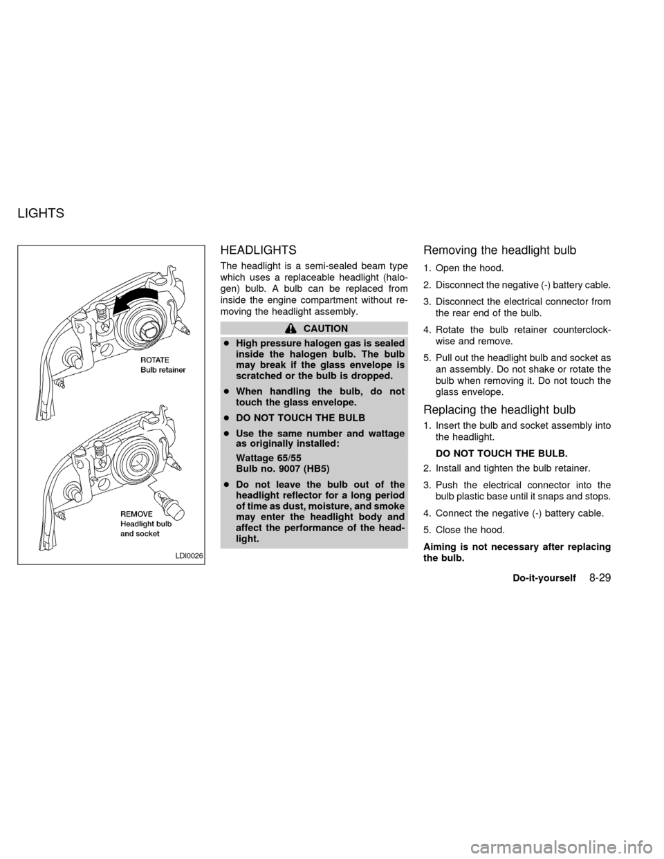
4. Rotate the bulb retainer counterclock-
wise and remove.
5. Pull out the headlight bulb and socket as
an assembly. Do not shake or rotate the
bulb when removing it. Do not touch the
glass envelope.
Replacing the headlight bulb
1. Insert the bulb and socket assembly into
the headlight.
DO NOT TOUCH THE BULB.
2. Install and tighten the bulb retainer.
3. Push the electrical connector into the
bulb plastic base until it snaps and stops.
4. Connect the negative (-) battery cable.
5. Close the hood.
Aiming is not necessary after replacing
the bulb.
LDI0026
LIGHTS
Do-it-yourself8-29
ZX
Page 189 of 240

If the vehicle front body has been repaired
and/or the headlight assembly has been
replaced, check aiming. Use the aiming
chart shown in the illustration.
cBasic illuminating area should be within
the range shown. Adjust headlamps ac-
cordingly.
FOG LIGHTS (if so equipped)
Replacing the fog light bulb
1. Remove screw.
2. Disconnect connector.
3. Push the fog light assembly towards the
front of the vehicle and pull out to expose
the rear of the assembly.
4. Rotate the bulb cover counterclockwise
and remove.
5. Lift the spring retainer.
6. Remove the fog light bulb from housing.
7. Disconnect the electrical connector.
LDI0028
8-32Do-it-yourself
ZX
Page 234 of 240

11 Index
A
Air bag (See supplemental restraint
system) ........................................................ 1-6
Air bag warning light .......................... 1-16, 2-8
Air cleaner housing filter ............................ 8-21
Air conditioner
Air conditioner operation ........................ 4-5
Air conditioner specification label ....... 10-12
Air conditioner system refrigerant and
lubrication recommendations ................ 10-7
Heater and air conditioner controls ........ 4-3
Servicing air conditioner ......................... 4-9
Air flow charts .............................................. 4-6
Alarm system (See theft warning) ............. 2-11
Anchor point locations ............................... 1-32
Antenna...................................................... 4-23
Anti-lock brake system (ABS).................... 5-19
Anti-lock brake warning light ....................... 2-9
Ashtray (See cigarette lighter and
ashtray) ...................................................... 2-20
Audio system
Compact Disc (CD) changer ................ 4-20
FM-AM radio with cassette player ........ 4-10
FM-AM radio with compact disc (CD)
player .................................................... 4-15
Automatic
Automatic power window switch .......... 2-26Automatic transmission fluid (ATF) ...... 8-13
Driving with automatic transmission ....... 5-7
Transmission selector lever lock
release .................................................. 5-10
B
Battery........................................................ 8-17
Battery
Charge warning light .............................. 2-8
Battery replacement (See multi-remote
control system) ............................................ 3-8
Before starting the engine ........................... 5-6
Belts (See drive belts) ............................... 8-19
Brake
Anti-lock brake system (ABS) .............. 5-19
Brake booster ....................................... 8-24
Brake fluid............................................. 8-15
Brake light (See stop light) ................... 8-33
Brake pedal .......................................... 8-23
Brake system ........................................ 5-18
Brake warning light ................................. 2-8
Brake wear indicators ................. 2-11, 8-24
Parking brake check ............................. 8-23
Parking brake operation ....................... 5-13
Self-adjusting brakes ............................ 8-23
Break-in schedule ...................................... 5-16
Bulb check/instrument panel ....................... 2-7Bulb replacement ....................................... 8-33
C
Capacities and recommended fuel/
lubricants.................................................... 10-2
Car phone or CB radio .............................. 4-23
Cargo net ................................................... 2-24
Cargo (See vehicle loading
information) .............................................. 10-14
Child restraint with top tether strap ........... 1-32
Child restraints ................................. 1-20, 1-25
Child safety rear door lock .......................... 3-4
Cigarette lighter (accessory) and
ashtray ....................................................... 2-20
Cleaning exterior and interior ...................... 7-2
Clock................................................. 4-11, 4-16
Clutch
Clutch fluid ............................................ 8-16
Clutch pedal.......................................... 8-25
Cold weather driving .................................. 5-20
Controls
Heater and air conditioner controls ........ 4-3
Coolant
Capacities and recommended fuel/
lubricants .............................................. 10-2
Changing engine coolant........................ 8-8
Checking engine coolant level ............... 8-6
ZX