2000 NISSAN QUEST glove box
[x] Cancel search: glove boxPage 41 of 292

Supplemental front air bag system
The driver supplemental air bag is located in
the center of the steering wheel. The front
passenger supplemental air bag is mounted in
the dashboard above the glove box.
These systems are designed to meet optional
certification requirements under U.S. regula-
tions. They are also permitted in Canada. The
optional certification allows front air bags to
be designed to inflate somewhat less force-
fully than previously.However, all of the
information, cautions and warnings in this
manual still apply and must be followed.
The supplemental front air bag system is
designed to inflate in higher severity frontal
collisions, although it may inflate if the forces
in another type of collision are similar to those
of a higher severity frontal impact. It may not
inflate in certain frontal collisions. Vehicle
damage (or lack of it) is not always an indica-
tion of proper supplemental air bag system
operation.
When the supplemental front air bag in-
flates, a fairly loud noise may be heard,
followed by the release of smoke. This
smoke is not harmful and does not indicate
a fire, but care should be taken to notintentionally inhale it, as it may cause irrita-
tion and choking. Those with a history of a
breathing condition should get fresh air
promptly.
The supplemental front air bags, along with
the use of seat belts, help to cushion the
impact force on the face and chest of the
occupant. They can help save lives and
reduce serious injuries. However, an inflat-
ing front air bag may cause facial abrasions
or other injuries. Front air bags do not
provide restraint to the lower body.
Seat belts should be correctly worn and the
driver and passenger seated upright as far
away as practical from the steering wheel or
instrument panel. Since the supplemental
front air bag inflates quickly in order to help
protect the occupant, the force of the front air
bag inflating can increase the risk of injury if
the occupant is too close to or is against the
air bag module during inflation.The air bag
deflates quickly after a collision.
The supplemental air bags operate only
when the ignition switch is in the ON or
START position.
After turning the ignition key to the ON
position, the supplemental air bag warn-
WRS0014
1-34Seats, restraints and supplemental air bag systems
ZX
Page 87 of 292

2 Instruments and controls
Meters and gauges ................................................2-3
Speedometer and odometer ..................................2-4
Tachometer ............................................................2-4
Engine coolant temperature gauge........................2-4
Fuel gauge .............................................................2-5
Warning/indicator lights and chimes ......................2-6
Checking bulbs .......................................................2-6
Warning lights.........................................................2-6
Indicator lights ........................................................2-8
Chimes .................................................................2-10
Theft warning (if so equipped) .............................2-10
Windshield wiper and washer switch ...................2-12
Rear window wiper and washer switches ............2-13
Rear window defogger switch ..............................2-14
Headlight control switch .......................................2-14
Autolamp switch (if so equipped) .........................2-15
Turn signal switch .............................................2-16
Cornering light ......................................................2-17
Hazard warning flasher switch .............................2-17
Horn ......................................................................2-18
Rear power socket ...............................................2-18
Cigarette lighter and ashtray (accessory) ............2-19Storage .................................................................2-20
Map pockets .........................................................2-20
Conversation mirror ..............................................2-20
Cup holders ..........................................................2-21
Glove box .............................................................2-22
Front seat convenience net (if so equipped) .......2-23
Cargo net..............................................................2-24
Parcel shelf (if so equipped) ................................2-25
Luggage rack .......................................................2-27
Windows ...............................................................2-27
Power windows ....................................................2-27
Power vent windows (if so equipped) ..................2-29
Manual vent windows ...........................................2-29
Sunroof (if so equipped).......................................2-30
Interior lights .........................................................2-31
Luggage ...............................................................2-31
Personal reading light ..........................................2-31
Map lights .............................................................2-32
Illuminated entry system ......................................2-32
Integrated HomeLinkTuniversal transceiver
(if so equipped) ....................................................2-32
Programming HomeLinkT.....................................2-33
ZX
Page 109 of 292

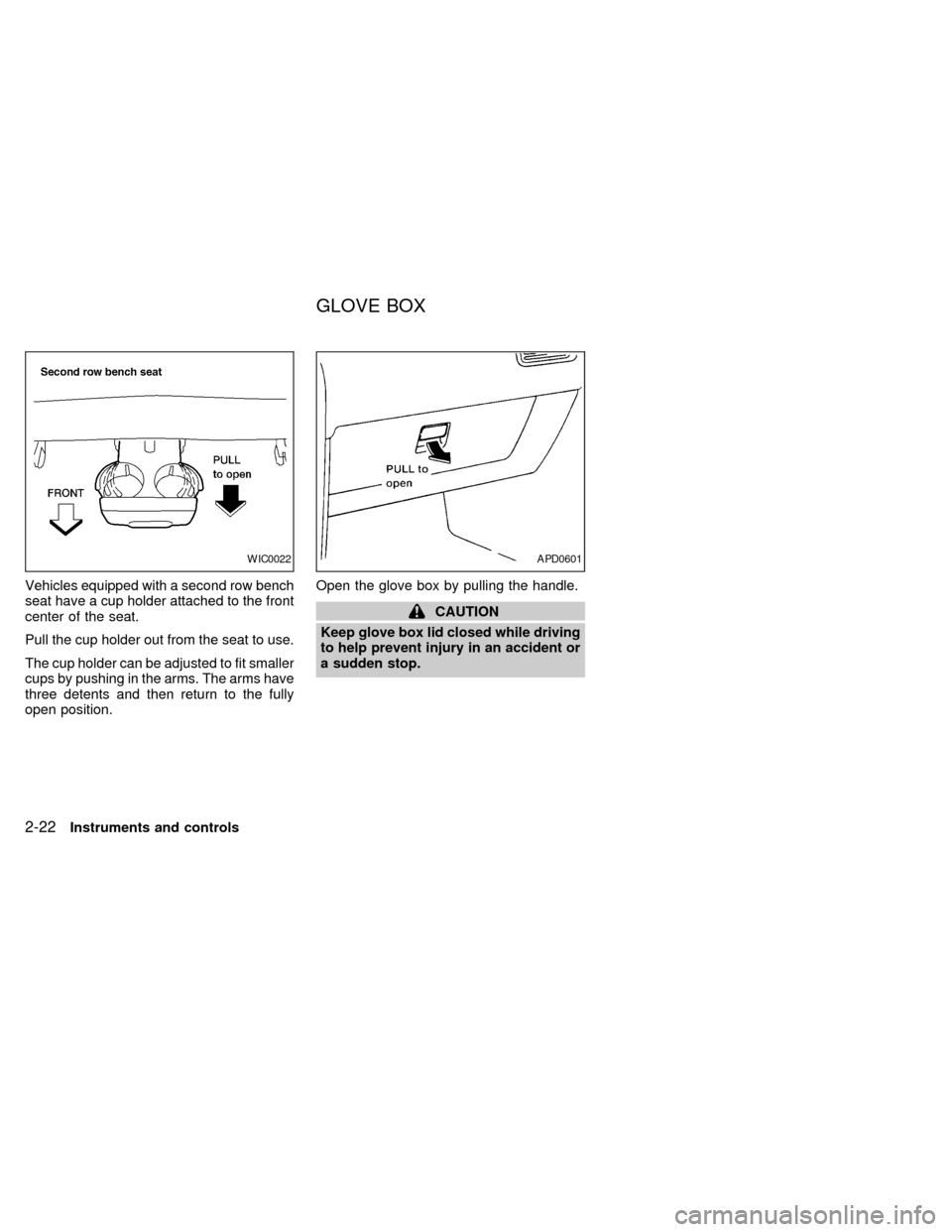
Vehicles equipped with a second row bench
seat have a cup holder attached to the front
center of the seat.
Pull the cup holder out from the seat to use.
The cup holder can be adjusted to fit smaller
cups by pushing in the arms. The arms have
three detents and then return to the fully
open position.Open the glove box by pulling the handle.
CAUTION
Keep glove box lid closed while driving
to help prevent injury in an accident or
a sudden stop.
WIC0022APD0601
GLOVE BOX
2-22Instruments and controls
ZX
Page 119 of 292

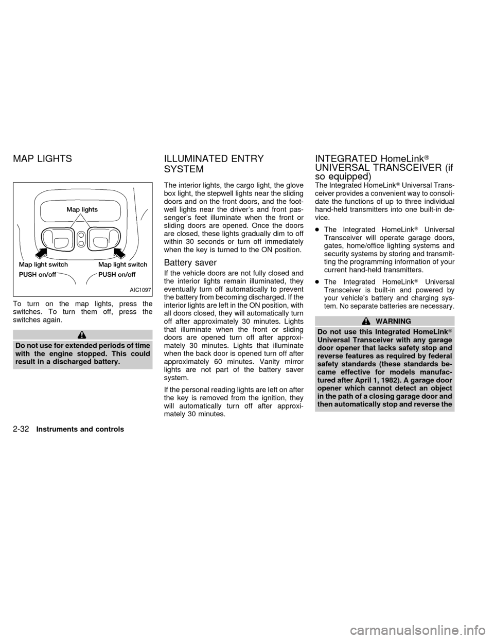
To turn on the map lights, press the
switches. To turn them off, press the
switches again.
Do not use for extended periods of time
with the engine stopped. This could
result in a discharged battery.The interior lights, the cargo light, the glove
box light, the stepwell lights near the sliding
doors and on the front doors, and the foot-
well lights near the driver's and front pas-
senger's feet illuminate when the front or
sliding doors are opened. Once the doors
are closed, these lights gradually dim to off
within 30 seconds or turn off immediately
when the key is turned to the ON position.
Battery saver
If the vehicle doors are not fully closed and
the interior lights remain illuminated, they
eventually turn off automatically to prevent
the battery from becoming discharged. If the
interior lights are left in the ON position, with
all doors closed, they will automatically turn
off after approximately 30 minutes. Lights
that illuminate when the front or sliding
doors are opened turn off after approxi-
mately 30 minutes. Lights that illuminate
when the back door is opened turn off after
approximately 60 minutes. Vanity mirror
lights are not part of the battery saver
system.
If the personal reading lights are left on after
the key is removed from the ignition, they
will automatically turn off after approxi-
mately 30 minutes.The Integrated HomeLinkTUniversal Trans-
ceiver provides a convenient way to consoli-
date the functions of up to three individual
hand-held transmitters into one built-in de-
vice.
cThe Integrated HomeLinkTUniversal
Transceiver will operate garage doors,
gates, home/office lighting systems and
security systems by storing and transmit-
ting the programming information of your
current hand-held transmitters.
c
The Integrated HomeLinkTUniversal
Transceiver is built-in and powered by
your vehicle's battery and charging sys-
tem. No separate batteries are necessary.
WARNING
Do not use this Integrated HomeLinkT
Universal Transceiver with any garage
door opener that lacks safety stop and
reverse features as required by federal
safety standards (these standards be-
came effective for models manufac-
tured after April 1, 1982). A garage door
opener which cannot detect an object
in the path of a closing garage door and
then automatically stop and reverse the
AIC1097
MAP LIGHTS ILLUMINATED ENTRY
SYSTEMINTEGRATED HomeLinkT
UNIVERSAL TRANSCEIVER (if
so equipped)
2-32Instruments and controls
ZX
Page 134 of 292

The interior lights, the cargo light, the glove
box light, the stepwell lights near the sliding
doors and on the front doors, and the foot-
well lights near the driver's and front pas-
senger's feet illuminate when the front or
sliding doors are opened. Once the doors
are closed, these lights gradually dim to off
within 30 seconds or turn off immediately
when the key is turned to the ON position.
Battery saver
If the vehicle doors are not fully closed and
the interior lights remain illuminated, they
eventually turn off automatically to prevent
the battery from becoming discharged. If the
interior lights are left in the ON position, with
all doors closed, they will automatically turn
off after approximately 30 minutes. Lights
that illuminate when the front or sliding
doors are opened turn off after approxi-
mately 30 minutes. Lights that illuminate
when the back door is opened turn off after
approximately 60 minutes. Vanity mirror
lights are not part of the battery saver
system.
If the personal reading lights are left on after
the key is removed from the ignition, they
will automatically turn off after approxi-
mately 30 minutes.1. Pull the hood lock release handle
s1
located below the instrument panel; the
hood then springs up slightly.
2. Pull up on the lever
s2at the front of the
hood and raise the hood.3. Insert the support rod
s3into the slot on
the underside of the hood.
4. When closing the hood, reset the support
rod to its original position, lower the hood
to approximately 12 inches above the
latch and release it. This allows proper
engagement of the hood latch.
APD1064
ILLUMINATED ENTRY
SYSTEMHOOD
Pre-driving checks and adjustments3-9
ZX
Page 202 of 292

Installing the spare tire
The spare tire is designed for emergency
use. See specific instructions under the
heading ``Wheels and tires'' in the ``Do-
it-yourself'' section of this manual.
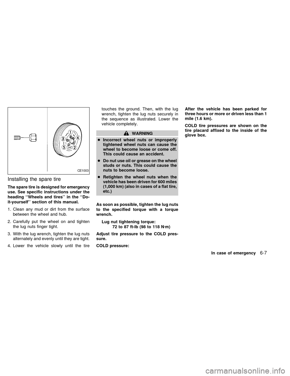
1. Clean any mud or dirt from the surface
between the wheel and hub.
2. Carefully put the wheel on and tighten
the lug nuts finger tight.
3. With the lug wrench, tighten the lug nuts
alternately and evenly until they are tight.
4. Lower the vehicle slowly until the tiretouches the ground. Then, with the lug
wrench, tighten the lug nuts securely in
the sequence as illustrated. Lower the
vehicle completely.
WARNING
cIncorrect wheel nuts or improperly
tightened wheel nuts can cause the
wheel to become loose or come off.
This could cause an accident.
cDo nut use oil or grease on the wheel
studs or nuts. This could cause the
nuts to become loose.
cRetighten the wheel nuts when the
vehicle has been driven for 600 miles
(1,000 km) (also in cases of a flat tire,
etc.)
As soon as possible, tighten the lug nuts
to the specified torque with a torque
wrench.
Lug nut tightening torque:
72 to 87 ft-lb (98 to 118 Nzm)
Adjust tire pressure to the COLD pres-
sure.
COLD pressure:After the vehicle has been parked for
three hours or more or driven less than 1
mile (1.6 km).
COLD tire pressures are shown on the
tire placard affixed to the inside of the
glove box.
CE1003
In case of emergency6-7
ZX
Page 244 of 292

COLD after the vehicle has been parked for
three or more hours, or driven less than 1
mile (1.6 km). COLD tire pressures are
shown on the tire placard affixed to the
glove box door.
WARNING
cImproperly inflated tires can fail sud-
denly and cause an accident.
cThe vehicle capacity weight is indi-
cated on the tire placard. Do not load
your vehicle beyond this capacity.
Overloading your vehicle may result
in reduced tire life, unsafe operating
conditions due to premature tire fail-
ure, or unfavorable handling charac-
teristics and could also lead to a
serious accident. Loading beyond
the specified capacity may also re-
sult in failure of other vehicle com-
ponents.
c
Before taking a long trip, or whenever
you have loaded your vehicle heavily,
use a tire pressure gauge to ensure
that the tire pressures are at the
specified level.
cDo not drive your vehicle over 85
MPH (140 km/h) unless it is equipped
with high speed rated tires. Driving
faster than 85 MPH (140 km/h) may
result in tire failure, loss of control
and possible injury.
TYPES OF TIRES
WARNING
When changing or replacing tires, be
sure all four tires are of the same type
(i.e., summer, all season or snow) and
construction. An authorized NISSAN
dealer may be able to help you with
information about tire type, size, speed
rating and availability. Replacement
tires may have a lower speed rating
than the factory equipped tires, and
may not match the potential maximum
vehicle speed. Never exceed the maxi-
mum speed rating of the tire.
All season tires
NISSAN specifies All Season tires to pro-
vide good performance all year, including
snowy and icy road conditions. All SeasonTires are identified by ``ALL SEASON''
and/or ``M&S'' on the tire sidewall. Snow
tires have better snow traction than All
Season tires and may be more appropriate
in some areas.
Snow tires
If snow tires are needed, it is necessary to
select tires equivalent in size and load rating
to the original equipment tires. If you do not,
it can adversely affect the safety and han-
dling of your vehicle.
Generally, snow tires have lower speed
ratings than factory equipped tires and may
not match the potential maximum vehicle
speed. Never exceed the maximum speed
rating of the tire.
If you operate your vehicle in snowy or icy
conditions, NISSAN recommends the use of
snow or all season tires on all four wheels.
For additional traction on icy roads, studded
tires may be used. However, some U.S.
states and Canadian provinces prohibit their
use. Check local, state and provincial laws
before installing studded tires. Skid and
traction capabilities of studded snow tires
on wet or dry surfaces may be poorer than
that of non-studded snow tires.
Do-it-yourself
8-29
ZX
Page 273 of 292

TIRE PLACARD
The cold tire pressure is shown on the tire
placard affixed to the inside of the glove
box.
AIR CONDITIONER
SPECIFICATION LABEL
The air conditioner specification label is
attached as shown.
Have your front license plate installed by
your NISSAN dealer.
ATI0561ATI1023
ATI0564
INSTALLING FRONT LICENSE
PLATE
10-12Technical and consumer information
ZX