2000 MITSUBISHI MONTERO door lock
[x] Cancel search: door lockPage 1713 of 1839
SWS -Troubleshooting54B-27
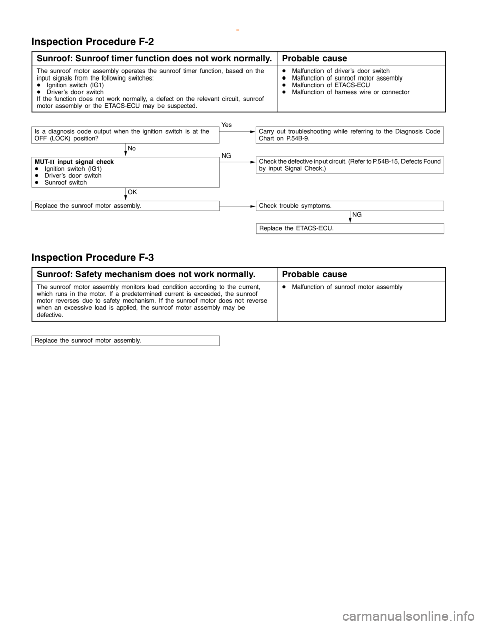
Inspection Procedure F-2
Sunroof: Sunroof timer function does not work normally.Probable cause
The sunroof motor assembly operates the sunroof timer function, based on the
input signals from the following switches:
DIgnition switch (IG1)
DDriver’s door switch
If the function does not work normally, a defect on the relevant circuit, sunroof
motor assembly or the ETACS-ECU may be suspected.DMalfunction of driver’s door switch
DMalfunction of sunroof motor assembly
DMalfunction of ETACS-ECU
DMalfunction of harness wire or connector
OK
NoNGCheck the defective input circuit. (Refer to P.54B-15, Defects Found
by input Signal Check.)
NG
Replace the ETACS-ECU.
Check trouble symptoms.Replace the sunroof motor assembly.
MUT-
IIinput signal check
DIgnition switch (IG1)
DDriver’s door switch
DSunroof switch
Is a diagnosis code output when the ignition switch is at the
OFF (LOCK) position?Ye sCarry out troubleshooting while referring to the Diagnosis Code
Chart on P.54B-9.
Inspection Procedure F-3
Sunroof: Safety mechanism does not work normally.Probable cause
The sunroof motor assembly monitorsload condition according to thecurrent,
which runs in the motor. If a predetermined current is exceeded, the sunroof
motor reverses due to safety mechanism. If the sunroof motor does not reverse
when an excessiveload is applied, the sunroof motorassembly may be
defective.DMalfunction of sunroof motor assembly
Replace the sunroof motor assembly.
www.WorkshopManuals.co.uk
Purchased from www.WorkshopManuals.co.uk
Page 1720 of 1839
SWS -TroubleshootingSWS -Troubleshooting54B-34
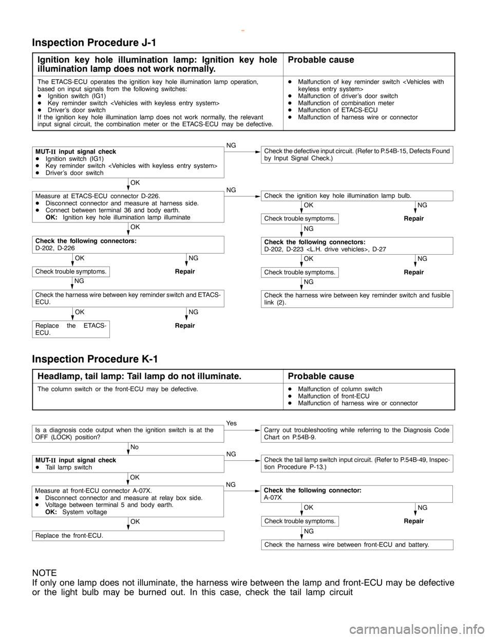
Inspection Procedure J-1
Ignition key hole illumination lamp: Ignition key hole
illumination lamp does not work normally.Probable cause
The ETACS-ECU operates the ignition keyhole illumination lamp operation,
based on input signals from the following switches:
DIgnition switch (IG1)
DKey reminder switch
DDriver’s door switch
If the ignition key hole illumination lampdoes not work normally, the relevant
input signal circuit, the combination meter or the ETACS-ECU may be defective.DMalfunction of key reminder switch
DMalfunction of driver’s door switch
DMalfunction of combination meter
DMalfunction of ETACS-ECU
DMalfunction of harness wire or connector
NGCheck the defective input circuit. (Refer to P.54B-15, Defects Found
by Input Signal Check.)
OK
NG
NG
Repair
OK
NG
Repair
NG
NG
Repair
OK
Replace the ETACS-
ECU.
NG
Repair
NG
Check the harness wire between key reminder switch and fusible
link (2).
OK
Check trouble symptoms.
NG
Check the following connectors:
D-202, D-223
OK
Check trouble symptoms.
Check the harness wire between key reminder switch and ETACS-
ECU.
OK
Check trouble symptoms.
Check the following connectors:
D-202, D-226
Check the ignition keyhole illumination lamp bulb.Measure at ETACS-ECU connector D-226.
DDisconnect connector and measure at harness side.
DConnect between terminal 36 and body earth.
OK:Ignition key hole illumination lamp illuminate
MUT-
IIinput signal check
DIgnition switch (IG1)
DKey reminder switch
DDriver’s door switch
Inspection Procedure K-1
Headlamp, tail lamp: Tail lamp do not illuminate.Probable cause
The column switch or the front-ECU may be defective.DMalfunction of column switch
DMalfunction of front-ECU
DMalfunction of harness wire or connector
OK
Replace the front-ECU.
Ye sCarry out troubleshooting while referring to the Diagnosis Code
Chart on P.54B-9.
No
NG
Check the taillampswitch input circuit. (Refer to P.54B-49, Inspec-
tion Procedure P-13.)
NG
Repair
NG
Check the harness wire between front-ECU and battery.
OK
Check trouble symptoms.
OK
NG
Check the following connector:
A-07XMeasure at front-ECU connector A-07X.
DDisconnect connector and measure at relay box side.
DVoltage between terminal 5 and body earth.
OK:System voltage
MUT-
IIinput signal check
DTail lampswitch
Is a diagnosis code output when the ignition switch is at the
OFF (LOCK) position?
NOTE
If only one lamp does not illuminate, the harness wire between the lamp and front-ECU may be defective
or the light bulb may be burned out. In this case, check the tail lamp circuit
www.WorkshopManuals.co.uk
Purchased from www.WorkshopManuals.co.uk
Page 1722 of 1839
SWS -Troubleshooting54B-36
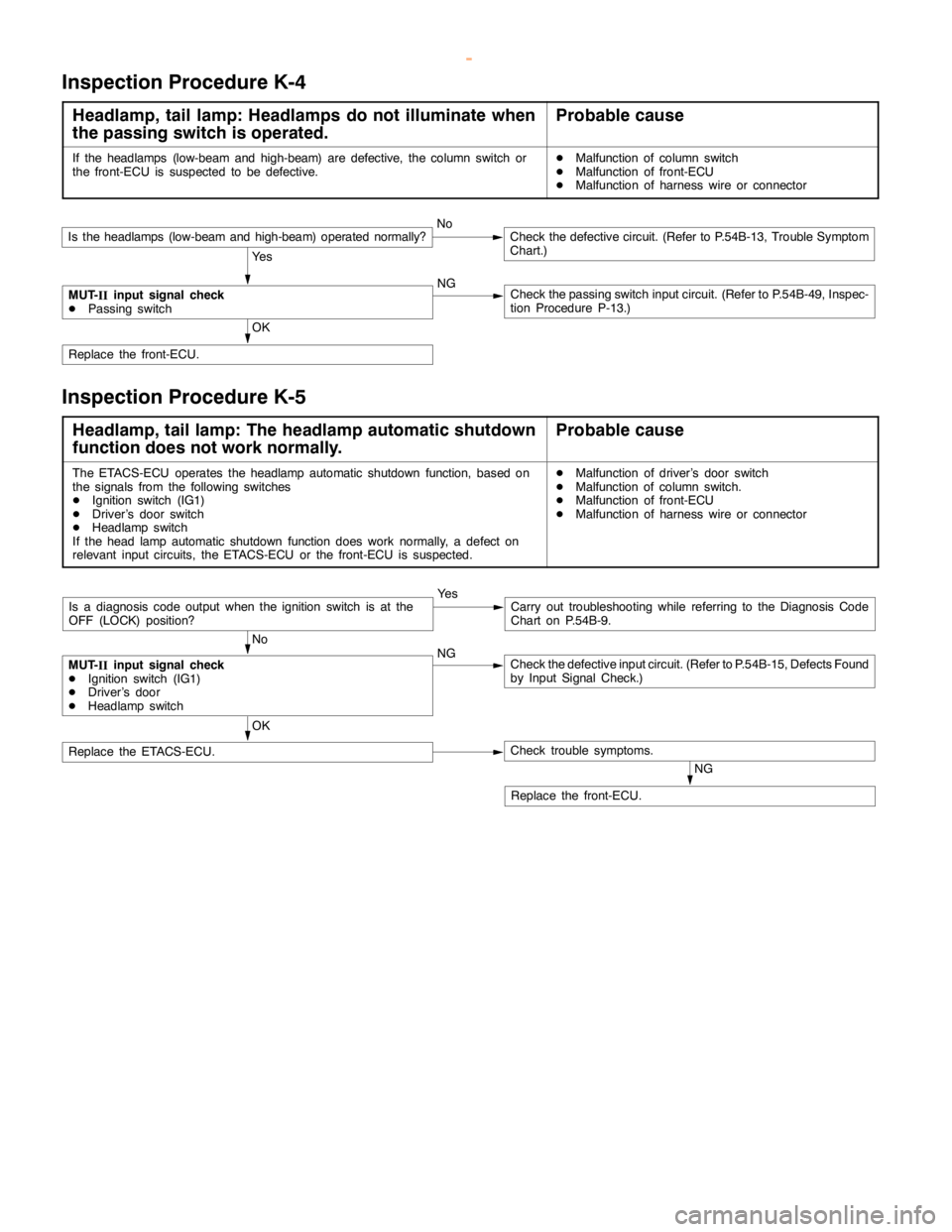
Inspection Procedure K-4
Headlamp, tail lamp: Headlamps do not illuminate when
the passing switch is operated.Probable cause
If the headlamps (low-beam and high-beam) are defective, the column switch or
the front-ECU is suspected to be defective.DMalfunction of column switch
DMalfunction of front-ECU
DMalfunction of harness wire or connector
OK
Replace the front-ECU.
Is the headlamps (low-beam and high-beam) operated normally?NoCheck the defective circuit. (Refer to P.54B-13, Trouble Symptom
Chart.)
Ye s
MUT-
IIinput signal check
DPassing switchNGCheck the passing switch input circuit. (Refer to P.54B-49, Inspec-
tion Procedure P-13.)
Inspection Procedure K-5
Headlamp, tail lamp: The headlamp automatic shutdown
function does not work normally.Probable cause
The ETACS-ECU operates theheadlamp automatic shutdown function,based on
the signals from the following switches
DIgnition switch (IG1)
DDriver’s door switch
DHeadlamp switch
If the head lamp automatic shutdown functiondoes work normally, a defect on
relevant input circuits, the ETACS-ECU or the front-ECU is suspected.DMalfunction of driver’s door switch
DMalfunction of column switch.
DMalfunction of front-ECU
DMalfunction of harness wire or connector
No
NG
Check the defective input circuit. (Refer to P.54B-15, Defects Found
by Input Signal Check.)
Ye sCarry out troubleshooting while referring to the Diagnosis Code
Chart on P.54B-9.
NG
Replace the front-ECU.
OK
Replace the ETACS-ECU.Check trouble symptoms.
MUT-
IIinput signal check
DIgnition switch (IG1)
DDriver’s door
DHeadlamp switch
Is a diagnosis code output when the ignition switch is at the
OFF (LOCK) position?
www.WorkshopManuals.co.uk
Purchased from www.WorkshopManuals.co.uk
Page 1727 of 1839
SWS -Troubleshooting54B-41
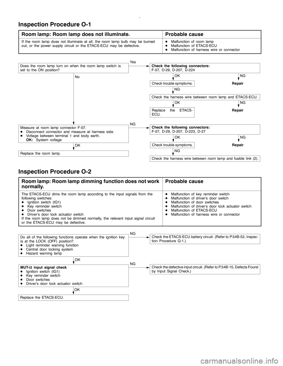
Inspection Procedure O-1
Room lamp: Room lamp does not illuminate.Probable cause
If the room lampdoes not illuminate at all, the roomlamp bulb may be burned
out, or the power supply circuit or the ETACS-ECU may be defective.DMalfunction of room lamp
DMalfunction of ETACS-ECU
DMalfunction of harness wire or connector
Ye s
NG
Repair
NG
No
NG
OK
Replace the room lamp.
NG
Repair
NG
Check the harness wire between roomlamp and fusiblelink (2).
OK
Replace the ETACS-
ECU.
NG
Repair
OK
Check trouble symptoms.
Check the following connectors:
F-07, D-29, D-207, D-223, D-27Measure at room lampconnector F-07.
DDisconnect connector and measure at harness side.
DVoltage between terminal 1 and body earth.
OK:System voltage
Check the harness wire between roomlamp and ETACS-ECU.
OK
Check trouble symptoms.
Check the following connectors:
F-07, D-29, D-207, D-224Does the roomlampturn on when the roomlampswitch is
set to the ON position?
Inspection Procedure O-2
Room lamp: Room lamp dimming function does not work
normally.Probable cause
The ETACS-ECU dims the roomlamp according to the inputsignals from the
following switches:
DIgnition switch (IG1)
DKey reminder switch
DDoor switches
DDriver’s door lock actuator switch
If the room lampdoes not bedimmed normally, the relevant input signalcircuit
or the ETACS-ECU may be defective.DMalfunction of key reminder switch
DMalfunction of driver’s door switch
DMalfunction of door switches
DMalfunction of driver’s door lock actuator switch
DMalfunction of ETACS-ECU
DMalfunction of harness wire or connector
NGCheck the ETACS-ECU battery circuit. (Refer to P.54B-53, Inspec-
tion Procedure Q-1.)
OK
NG
Check the defective input circuit. (Refer to P.54B-15, Defects Found
by Input Signal Check.)
OK
Replace the ETACS-ECU.
MUT-
IIinput signal check
DIgnition switch (IG1)
DKey reminder switch
DDoor switches
DDriver’s door lock actuator switch
Do all of the following functions operate when the ignition key
is at the LOCK (OFF) position?
DLight reminder warning function
DCentral door locking system
DHazard warninglamp
www.WorkshopManuals.co.uk
Purchased from www.WorkshopManuals.co.uk
Page 1734 of 1839
SWS -Troubleshooting54B-48
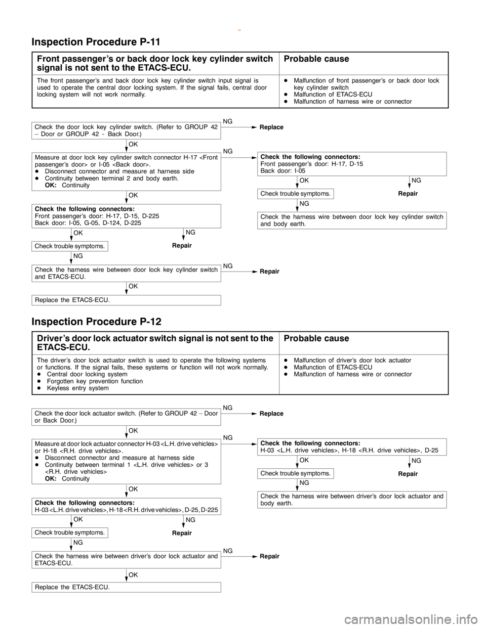
Inspection Procedure P-11
Front passenger’s or back door lock key cylinder switch
signal is not sent to the ETACS-ECU.Probable cause
The front passenger’s and back door lock key cylinder switch input signal is
used to operate the central door locking system. If the signal fails, central door
locking system will not work normally.DMalfunction of front passenger’s or back door lock
key cylinder switch
DMalfunction of ETACS-ECU
DMalfunction of harness wire or connector
NG
Replace
OK
OK
Replace the ETACS-ECU.
OK
NG
NG
Repair
NG
RepairOK
NG
Check the harness wire between door lock key cylinder switch
and body earth.
NG
Check the harness wire between door lock key cylinder switch
and ETACS-ECU.NG
Repair
OK
Check trouble symptoms.
Check the following connectors:
Front passenger’s door: H-17, D-15, D-225
Back door: I-05, G-05, D-124, D-225
Check trouble symptoms.
Check the following connectors:
Front passenger’s door: H-17, D-15
Back door: I-05Measure at door lock key cylinder switch connector H-17
DDisconnect connector and measure at harness side
DContinuity between terminal 2 and body earth.
OK:Continuity
Check the door lock key cylinder switch. (Refer to GROUP 42
– Door or GROUP 42 - Back Door.)
Inspection Procedure P-12
Driver’s door lock actuator switch signal is not sent to the
ETACS-ECU.Probable cause
The driver’s door lock actuator switch is used to operate the following systems
or functions. If the signal fails, these systems or function will not work normally.
DCentral door locking system
DForgotten key prevention function
DKeyless entry systemDMalfunction of driver’s door lock actuator
DMalfunction of ETACS-ECU
DMalfunction of harness wire or connector
OK
Replace the ETACS-ECU.
OK
NG
NG
Repair
NG
Repair
NG
Check the harness wire between driver’s door lock actuator and
body earth.
NG
Check the harness wire between driver’s door lock actuator and
ETACS-ECU.NG
Repair
OK
Check trouble symptoms.
OK
Check the following connectors:
H-03
OK
Check trouble symptoms.
Check the following connectors:
H-03
or H-18
DDisconnect connector and measure at harness side
DContinuity between terminal 1
OK:Continuity
Check the door lock actuator switch. (Refer to GROUP 42 – Door
or Back Door.)NG
Replace
www.WorkshopManuals.co.uk
Purchased from www.WorkshopManuals.co.uk
Page 1739 of 1839
SWS -Troubleshooting54B-53
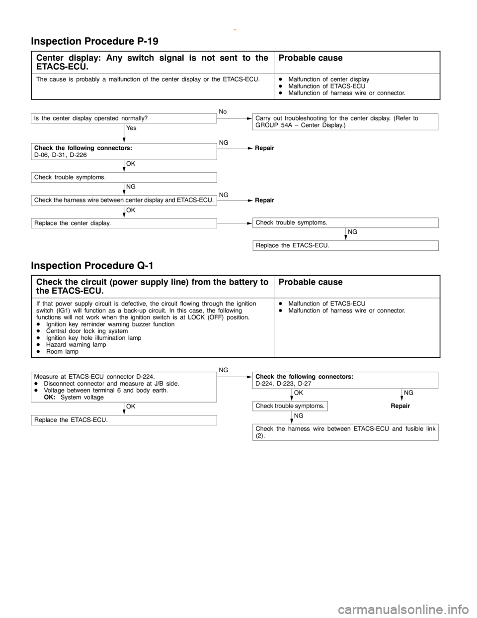
Inspection Procedure P-19
Center display: Any switch signal is not sent to the
ETACS-ECU.Probable cause
The cause is probably a malfunction of the center display or the ETACS-ECU.DMalfunction of center display
DMalfunction of ETACS-ECU
DMalfunction of harness wire or connector.
Ye s
NG
Repair
NG
Replace the ETACS-ECU.
OK
Replace the center display.Check trouble symptoms.
NG
Check the harness wire between center display and ETACS-ECU.NG
Repair
OK
Check trouble symptoms.
Check the following connectors:
D-06, D-31, D-226
Is the center display operated normally?NoCarry out troubleshooting for the center display. (Refer to
GROUP 54A – Center Display.)
Inspection Procedure Q-1
Check the circuit (power supply line) from the battery to
the ETACS-ECU.Probable cause
If that power supply circuit is defective, the circuit flowing through the ignition
switch (IG1) will function as a back-up circuit. In this case, the following
functions will not work when the ignition switch is at LOCK (OFF) position.
DIgnition key reminder warning buzzer function
DCentral door lock ing system
DIgnition key hole illumination lamp
DHazard warninglamp
DRoom lampDMalfunction of ETACS-ECU
DMalfunction of harness wire or connector.
NG
NG
Repair
NG
Check the harness wire between ETACS-ECU and fusible link
(2).
OK
Replace the ETACS-ECU.
OK
Check trouble symptoms.
Check the following connectors:
D-224, D-223, D-27Measure at ETACS-ECU connector D-224.
DDisconnect connector and measure at J/B side.
DVoltage between terminal 6 and body earth.
OK:System voltage
www.WorkshopManuals.co.uk
Purchased from www.WorkshopManuals.co.uk
Page 1741 of 1839

SWS -Troubleshooting54B-55
Terminal
No.Normal condition Checking requirements Check items
26Key reminder switch signal inputKey reminder switch: ON (Ignition key
removed)0V
27Hazard warning lamp switch signal
inputHazard warning lamp switch: ON0V
29Recognition line of daytime running
lamp (DRL)
31Data request signal outputAlways0 - 5 V (pulse
signal)
34Windshield intermittent wiper interval
adjusting knob signal inputIgnition switch: ACC,
Windshield intermittent wiper interval
adjusting knob: FAST®SLOW0®2.5 V
35Back-up lamp switch signal input
Shift lever: RSystem voltage
Inhibitor switch (reverse) signal input
Ignition switch: ON,
Selector lever: RSystem voltage
36Ignition key hole illumination lamp
outputWhen ignition key hole illumination
lamp is lighted2 V or less
37Diagnosis code or input signal check
outputWhen diagnosis code is output0 - 12 V (pulse
signal)
When input signal check is output0, 12 V (When input
pulse signal is
changed)
40Rear fog lamp relay outputWhen rear fog lamp is lighted2 V or less
53Front passenger’s and back door lock
key cylinder switch (LOCK) signal inputFront passenger’s or back door lock key
cylinder switch: LOCK0V
54Front passenger’s and back door lock
key cylinder switch (UNLOCK) signal
inputFront passenger’s or back door lock
switch: UNLOCK0V
55Driver’s door lock actuator switch
(LOCK) signal inputDriver’s door lock actuator switch:
LOCK0V
56Driver’s door lock actuator switch
(UNLOCK) signal inputDriver’s door lock actuator switch:
UNLCOK0V
www.WorkshopManuals.co.uk
Purchased from www.WorkshopManuals.co.uk
Page 1746 of 1839

SWS -On-vehicle Service54B-60
ON-VEHICLE SERVICE
ADJUSTMENT PROCEDURES OF SWS FUNCTION
Through special operation of input switches, it is possible to disable and enable the functions listed below.
Settings are retained even if the battery is disconnected.
DKeyless entry hazard answerback function
DInitialization of above mentioned functions
Configuration Mode Entry Conditions
1. Set each switch at the following condition.
DHazard warning lamp switch: OFF
DDiagnosis control: ON (MUT-II
connected or terminal 1 of diagnosis connector connected to earth)
DKey reminder switch: OFF (ignition key inserted)
DIgnition switch: LOCK (OFF)
DDriver’s door switch: OFF (driver’s door closed)
2. When the windshield washer switch is continuously turned ON for more than 10 seconds, the buzzer
integrated in the ETACS-ECU sounds once and the mode is switched to the configuration mode.
Configuration Mode Cancellation Conditions
The ETACS-ECU cancels the configuration mode when any of the conditions listed below is satisfied.
DDiagnosis control: OFF (MUT-II
disconnected or terminal 1 of diagnosis connector disconnected from
earth)
DKey reminder switch: ON (ignition key removed)
DIgnition switch: any position other than LOCK (OFF)
DDriver’s door switch: ON (driver’s door open)
DNo configuration performed within three minutes of entry to configuration mode (If configuration is
performed within first three minutes, monitoring continues for three minutes from that point.)
Configuration of Functions
FunctionConfiguration procedure
Keyless entry hazard
answerbackIf the transmitter’s LOCK switch is turned ON twice within two seconds, the lock answerback
function’s enabled/disabled status is inverted.
D
When function is enabled, buzzer sounds once (initial status).
D
When function is disabled, buzzer sounds twice.
If the transmitter’s UNLOCK switch is turned ON twice within two seconds, the unlock
answerback function’s enabled/disabled status is inverted.
D
When function is enabled, buzzer sounds once (initial status).
D
When function is disabled, buzzer sounds twice.
Initialization of above
mentioned functionsIf the windshield washer switch is turned ON for more than 20 seconds, the buzzer sounds
twice and all functions are initialized. (The configuration mode entry buzzer sounds after 10
seconds, but the switch must be kept ON for 20 seconds to achieve initialization.)
IF the windshield washer switch ins kept ON for more than 20 seconds without prior entry
of the configuration mode, the configuration mode is entered after 10 seconds and
initialization does not take place.
www.WorkshopManuals.co.uk
Purchased from www.WorkshopManuals.co.uk