2000 MITSUBISHI MONTERO torque
[x] Cancel search: torquePage 950 of 1839

Page 952 of 1839

AUTOMATIC TRANSMISSION -Troubleshooting AUTOMATIC TRANSMISSION -Troubleshooting 23-51
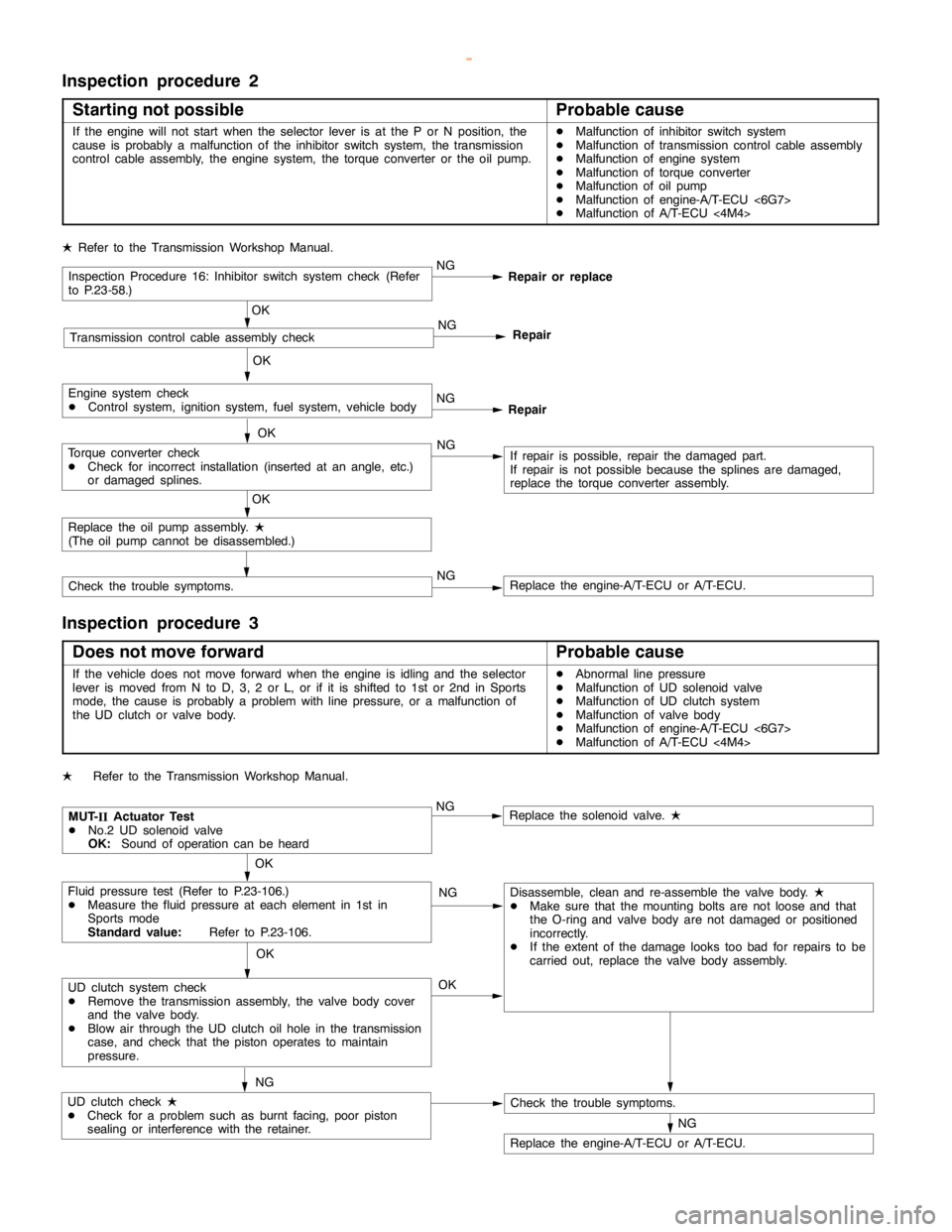
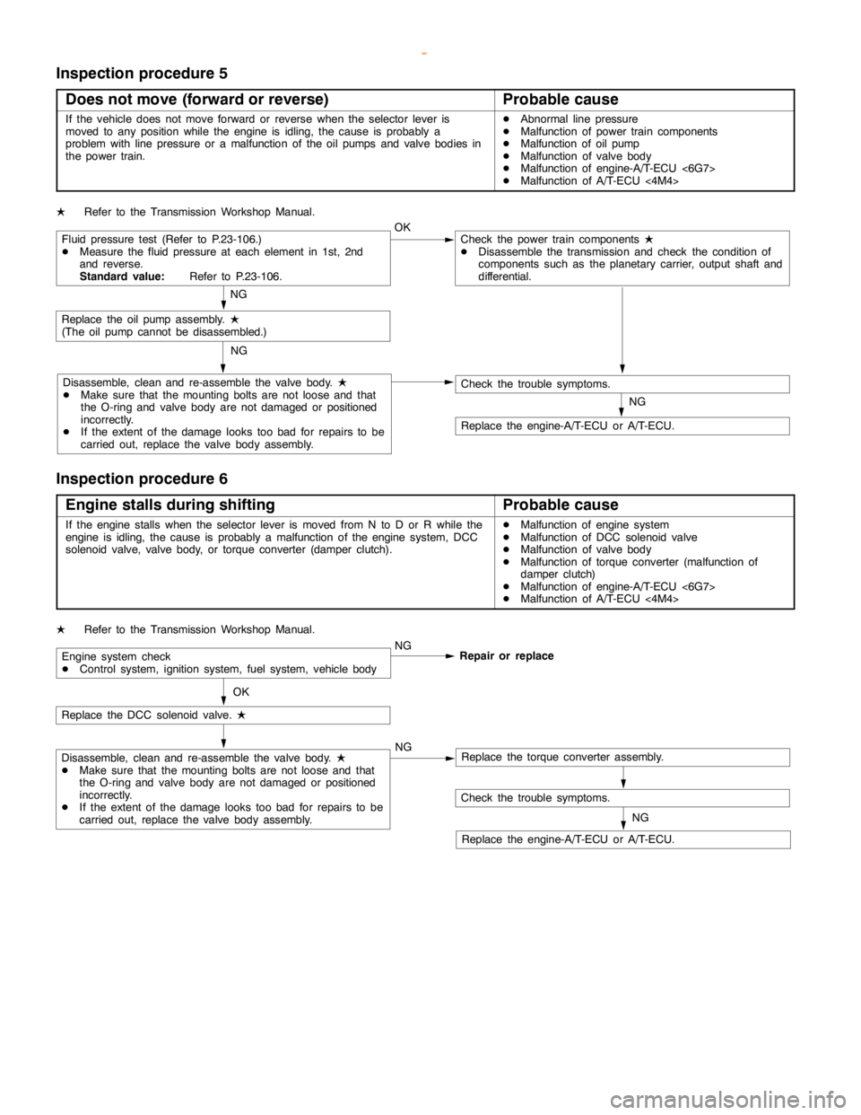
Inspection procedure 5
Does not move (forward or reverse)
Probable cause
If the vehicle does not move forward or reverse when the selector lever is
moved to any position while the engine is idling, thecause is probably a
problem with line pressure or a malfunction of the oil pumps and valve bodies in
the power train.DAbnormal line pressure
DMalfunction of power train components
DMalfunction of oil pump
DMalfunction of valve body
DMalfunction of engine-A/T-ECU <6G7>
DMalfunction of A/T-ECU<4M4>
LRefer to the Transmission Workshop Manual.
Fluid pressure test (Refer to P.23-106.)
DMeasure the fluid pressure at each element in 1st, 2nd
and reverse.
Standard value:Refer to P.23-106.OKCheck the power train components
L
DDisassemble the transmission and check the condition of
components such as the planetary carrier, output shaft and
differential.
NG
Replace the oil pumpassembly.
L
(The oilpump cannot be disassembled.)
Disassemble, clean and re-assemble the valve body.
L
DMake sure that the mounting bolts are not loose and that
the O-ring and valve body are notdamaged or positioned
incorrectly.
DIf the extent of thedamagelooks too bad for repairs to be
carried out, replace the valve body assembly.NG
NG
Check the trouble symptoms.
Replace the engine-A/T-ECU or A/T-ECU.
Inspection procedure 6
Engine stalls during shifting
Probable cause
If the enginestalls when the selector lever is moved from N to D or R while the
engine is idling, thecause is probably a malfunction of theenginesystem, DCC
solenoid valve, valve body, or torque converter (damper clutch).DMalfunction of enginesystem
DMalfunction of DCC solenoid valve
DMalfunction of valve body
DMalfunction of torque converter (malfunction of
damper clutch)
DMalfunction of engine-A/T-ECU <6G7>
DMalfunction of A/T-ECU<4M4>
LRefer to the Transmission Workshop Manual.
Engine system check
DControl system, ignition system, fuel system, vehicle bodyNG
Repair or replace
OK
Replace the DCC solenoid valve.
L
Disassemble, clean and re-assemble the valve body.
L
DMake sure that the mounting bolts are not loose and that
the O-ring and valve body are notdamaged or positioned
incorrectly.
DIf the extent of thedamagelooks too bad for repairs to be
carried out, replace the valve body assembly.NGReplace the torque converter assembly.
Check the trouble symptoms.
Replace the engine-A/T-ECU or A/T-ECU.NG
www.WorkshopManuals.co.uk
Purchased from www.WorkshopManuals.co.uk
Page 958 of 1839

Page 1001 of 1839

AUTOMATIC TRANSMISSION -On-vehicle Service23-100
Specified lubricant:
Hypoid gear oil SAE 75W-90 or 75W-85W
conforming to API GL-4
Oil level: 2.8 L
4. Install the oil filler plug, and tighten it to the specified
torque.
Tightening torque: 32±
2N×
m
www.WorkshopManuals.co.uk
Purchased from www.WorkshopManuals.co.uk
Page 1009 of 1839

AUTOMATIC TRANSMISSION -On-vehicle Service23-108
Symptom Problem location
Abnormal RED pressure onlyMalfunction of oil seal U or V
Malfunction of reaction solenoid valve
Malfunction of reduction pressure control valve
Blocked orifices
Incorrect valve body installation
Abnormal DR pressure onlyBlocked oil cooler
Malfunction of oil seal N
Malfunction of damper clutch control solenoid valve
Malfunction of damper clutch control solenoid valve
Malfunction of torque converter pressure control valve
Blocked orifices
Incorrect valve body installation
Pressure applied to non-operating elementIncorrect transmission control cable adjustment
Malfunction of manual valve
Incorrect valve body installation
www.WorkshopManuals.co.uk
Purchased from www.WorkshopManuals.co.uk
Page 1053 of 1839

FRONT AXLE -Service Specifications/Lubricants26-4
SERVICE SPECIFICATIONS
ItemStandard valueLimit
Wheel bearing axis backlash mm-0
Front axle total backlash mm-11
Solenoid valve resistanceW36 - 46-
Hub rotation starting torque N×m-1.75
Setting of D.O.J. boot length mm80±5-
Opening dimension of the spe-
cial tool (MB991561) mmWhen the B.J. boot band
(small) is crimped.2.9-
When the B.J. boot band
(big) is crimped.3.2-
Crimped width of the B.J. boot band mm2.4 - 2.8-
Crimped height of B. J. boot band (big) mm-9.5
Final drive gear backlash mm0.11 - 0.16-
Drive gear runout mm-0.05
Differential gear backlash mm0 - 0.0760.2
Drive pinion turning torque N×mWithout oil seal0.83 - 1.19-
With oil sealCompanion flange (oil seal contact
surface) with anti-rust oil
0.93 - 1.128-
Companion flange (oil seal contact
surface) with gear oil
0.97 - 1.32-
LUBRICANTS
ItemsSpecified lubricantsQuantity
Front differential gear oilHypoid gear oil API classification GL-5 or higher, SAE
viscosity No. 90, 80W1.2 L
D.O.J. boot greaseRepair kit grease4M41-M/T:135±10 g
4M41-A/T, 6G7:
100±10 g
U.J.boot greaseRepair kit grease4M41-M/T:180±10 g
4M41-A/T, 6G7:
135±10 g
www.WorkshopManuals.co.uk
Purchased from www.WorkshopManuals.co.uk
Page 1104 of 1839

REAR AXLE -General Information27-2
GENERAL INFORMATION
The rear axle has the following features.
DD.O.J.-type on the differential side and B.J.-type on the hub side constant velocity joints are featured
in the drive shaft.
DLarge capacity and high rigidity taper-roller type unit bearing in the wheel bearing is featured.
DThe hybrid LSD and differential lock with LSD which benefit driving on muddy and rough roads are
featured as an option.
DABS rotor to detect wheel speed is press-fitted in the drive shaft.
NOTE
The structure of normal differential and hybrid LSD is basically the same as featured in existing models.
SPECIFICATIONS
ItemNormal DifferentialHybrid LSDDifferential Lock
with LSD
Reduction gear typeHypoid gearHypoid gearHypoid gear
Reduction ratio4.900*1, 3.917*2,
4.100*3, 4.300*44.900*1, 3.917*2,
4.100*3, 4.300*44.900*1, 3.917*2,
4.100*3, 4.300*4
LSD type-Torque sensing +
VCUTorque sensing
Differential gear type (Type´
number of gears)Side gearStraight bevel gear
´2Helical gear´2Helical gear´2
Pinion gearStraight bevel gear
´2Long pinion´4,
Short pinion´4Long pinion´4,
Short pinion´4
Number
of teethDrive gear49*1, 47*2, 41*3,
43*449*1, 47*2, 41*3,
43*449*1, 47*2, 41*3,
43*4
Drive pinion10*1,*3,*4, 12*210*1,*3,*4, 12*210*1,*3,*4, 12*2
Side gear182222
Pinion gear1077
Bearings (Outside diameter´Side90.0´55.090.0´55.090.0´55.0
Inside diameter) mm
Front68.3´30.268.3´30.268.3´30.2
Rear79.4´36.579.4´36.579.4´36.5
NOTE
*1:4D56
*2:4M41-A/T
*3:4M41-M/T
*4:6G74 GDI
www.WorkshopManuals.co.uk
Purchased from www.WorkshopManuals.co.uk
Page 1310 of 1839

37A-1
STEERING
CONTENTS
GENERAL INFORMATION 2..................
SERVICE SPECIFICATIONS 5.................
LUBRICANTS 5..............................
SEALANT AND ADHESIVE 5.................
SPECIAL TOOLS 6..........................
ON-VEHICLE SERVICE 8.....................
Steering Wheel Free Play Check 8..............
Steering Angle Check 8........................
Tie Rod End Ball Joint Starting Torque Check 8..
Stationary Steering Effort Check 9...............
Steering Wheel Returnability Check 9............
Oil Pump Belt Tension Check <6G7,4D5> 9......Power Steering Fluid Level Check 10............
Power Steering Fluid Replacement 10...........
Power Steering System Bleeding 10.............
Oil Pump Pressure Test 11.....................
Power Steering Oil Pressure Switch Check
<6G7,4M4> 12.................................
Ball Joint Dust Cover Check 12.................
STEERING WHEEL AND SHAFT* 13.........
POWER STEERING GEAR BOX AND
LINKAGE 16................................
POWER STEERING OIL PUMP 30...........
POWER STEERING OIL HOSES 35..........
WARNINGS REGARDING SERVICING OF SUPPLEMENTAL RESTRAINT SYSTEM (SRS) EQUIPPED VEHICLES
WARNING!
(1) Improper service or maintenance of any component of the SRS, or any SRS-related component, can lead to personal
injury or death to service personnel (from inadvertent firing of the air bag) or to the driver and passenger (from rendering
the SRS inoperative).
(2) Service or maintenance of any SRS component or SRS-related component must be performed only at an authorized
MITSUBISHI dealer.
(3) MITSUBISHI dealer personnel must thoroughly review this manual, and especially its GROUP 52B - Supplemental
Restraint System (SRS) before beginning any service or maintenance of any component of the SRS or any SRS-related
component.
NOTE
The SRS includes the following components: SRS-ECU, SRS warning lamp, air bag module, clock spring and interconnecting
wiring. Other SRS-related components (that mayhave to be removed/installed in connectionwith SRS service or maintenance) are
indicated in the table of contents by an asterisk(*).
www.WorkshopManuals.co.uk
Purchased from www.WorkshopManuals.co.uk