2000 MITSUBISHI MONTERO reset
[x] Cancel search: resetPage 1591 of 1839

CHASSIS ELECTRICAL-Ignition Switch and Immobilizer <4D56>54A-21
ENCRYPTED CODE REGISTRATION METHOD
AND RESETTING THE CODE TO THE
FACTORY SETTING
Register the encrypted code in the immobilizer-ECU and then
reset the code to the factory setting after parts have been
replaced.
Replacement partEncrypted
code
Ignition keyNecessary
Ignition key ring antenna and immobilizer-ECUNecessary
Engine-ECU*Necessary
NOTE
* : If the engine-ECU is replaced, the ignition key ring antenna
and immobilizer-ECU and ignition key should be replaced
together with it.
Each engine-ECU has an individual information for
immobilizer-ECU, and the individual information is registered
in the immobilizer-ECU.
ENCRYPTED CODE REGISTRATION METHOD
If using an ignition key that has just been newly purchased,
or if the immobilizer-ECU has been replaced, you will need
to register the encrypted codes for each ignition key being
used into the immobilizer-ECU. (A maximum of eight different
encrypted codes can be registered.)
Moreover, when the immobilizer-ECU has been replaced, you
will need to use the MUT-II
to register the password that
the user specifies into the immobilizer-ECU. (Refer to the
MUT-II
instruction manual for instructions on using the MUT-II
.)
Caution
Because registering of the encrypted codes is carried
out after all previously-registered codes have been
erased, you should have ready all of the ignition keys
that have already been registered.
www.WorkshopManuals.co.uk
Purchased from www.WorkshopManuals.co.uk
Page 1624 of 1839

CHASSIS ELECTRICAL -Clock or Center Display54A-54
BEFORE REMOVING THE BATTERY
The Center display has a large amount of data unique to the vehicle in its memory. When the battery
cable is disconnected, that memory is affected as shown in the table below. Accordingly, it is necessary
to make sure that you take notes of important information before disconnecting the battery cable.
FunctionInput function/memoryWhen battery cable is disconnected
Clock set on displayCurrent timeRetains data for approx. 1 hour
Vehicle model setShort (3-door models)/long (5-door
models)Retains data for approx. 1 hour
Brightness set for displayPosition set on displayRetains data for approx. 1 hour
Unit set for trip computerkm or mile, L/100km or mpg or km/L
Average vehicle speed after resetRetains data for approx. 1 hour
Average vehicle speed on displayAverage vehicle speed after resetRetains data for approx. 1 hour
Average fuel consumption on displayAverage fuel consumption after resetRetains data for approx. 1 hour
Cruising range on displayCruising range, fuel economyRetains data for approx. 1 hour
Outside temperature on displayOutside temperature after the ignition
switch is turned to the OFF(LOCK)
position.Retains data for approx. 1 hour
* The outside temperature sensor
is located near the engine.
Therefore, incorrectly high
temperature may be displayed
when the battery cable is
reconnected within one hour.
DIAGNOSIS FUNCTION FOR CENTER DISPLAY
Center display has the following diagnosis function:
FunctionContents
Service functionThere are the following 4 diagnosis modes available
1. Check of vehicle informationThe vehicle, short (3-door models)/long (5-door models) set
2. Check of LCD segmentsThe LCD segments for display available to light on or not
3. Check of sensorsOutside temperature, voltage of fuel gauge unit, system voltage, fuel amount
remains, fuel economy calculated after supply of fuel
4. Check of units connected into
the center displayThe units connected on display
Voltage (%) on terminal for MUT-II
Vehicle speed signal sent by engine-ECU
Oscillating signal
www.WorkshopManuals.co.uk
Purchased from www.WorkshopManuals.co.uk
Page 1638 of 1839

CHASSIS ELECTRICAL -Radio/Tape Player54A-68
RADIO/TAPE PLAYER
TROUBLESHOOTING
QUICK-REFERENCE TROUBLESHOOTING CHART
ItemsProblem symptomRelevant chart
NoiseNoise appears at certain places when travelling.A-1
Mixed with noise, only at night.A-2
Broadcasts can be heard but UKW/MW/LW has a lot of noise.A-3
There is noise when starting the engine.A-4
Some noise appears when there is vibration or shocks during
travelling.A-5
Ever-present noise.A-6
RadioWhen switch is set to ON, no power is available.B-1
No sound from one speaker.B-2
There is noise but no reception for UKW/MW/LW or no sound from
UKW/MW/LW.B-3
Insufficient sensitivity.B-4
Distortion on UKW/MW/LW.B-5
Too few automatic select stations.B-6
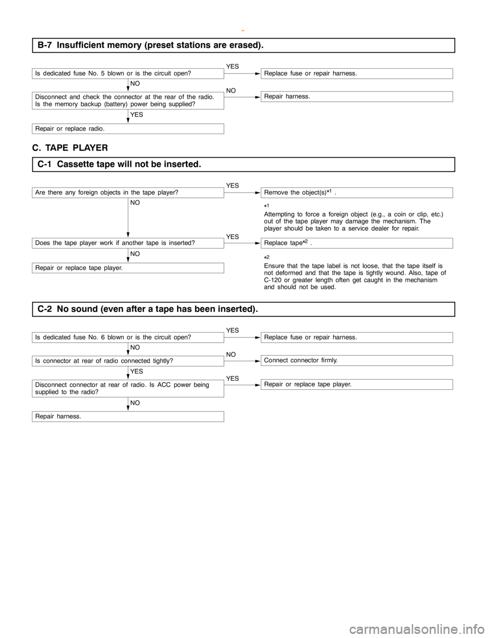
Insufficient memory (preset stations are erased).B-7
Tape playerCassette tape will not be inserted.C-1
No sound.C-2
No sound from one speaker.C-3
Sound quality is poor, or sound is weak.C-4
Cassette tape will not be ejected.C-5
Uneven revolution. Tape speed is fast or slow.C-6
Faulty auto reverse.C-7
Tape gets caught in mechanism.C-8
www.WorkshopManuals.co.uk
Purchased from www.WorkshopManuals.co.uk
Page 1647 of 1839

CHASSIS ELECTRICAL -Radio/Tape Player54A-77
B-7 Insufficient memory (preset stations are erased).
Is dedicated fuse No. 5 blown or is the circuitopen?YESReplace fuse or repair harness.
NO
Disconnect and check the connector at the rear of the radio.
Is the memory backup (battery) powerbeing supplied?NORepair harness.
YES
Repair or replace radio.
C. TAPE PLAYER
C-1 Cassette tape will not be inserted.
Are there any foreign objects in the tape player?YESRemove the object(s)*1.
NO*1
Attempting to force a foreign object (e.g., a coin or clip, etc.)
out of the tape player maydamage the mechanism. The
player should be taken to a service dealer for repair.
Does the tape player work if another tape is inserted?YESReplace tape*2.
NO
Repair or replace tape player.
*2
Ensure that the tape label is not loose, that the tape itself is
not deformed and that the tape is tightly wound. Also, tape of
C-120 or greater length often get caught in the mechanism
and should not be used.
C-2 No sound (even after a tape has been inserted).
Is dedicated fuse No. 6 blown or is the circuitopen?YESReplace fuse or repair harness.
NO
Is connector at rear of radio connected tightly?NOConnect connector firmly.
YES
Disconnect connector at rear of radio. Is ACC powerbeing
supplied to the radio?YESRepair or replace tape player.
NO
Repair harness.
www.WorkshopManuals.co.uk
Purchased from www.WorkshopManuals.co.uk
Page 1691 of 1839

SWS -General InformationSWS -General Information54B-5
HEADLAMP WASHER
If the headlamp washer switch at the steering
column is placed in the ON position when the ignition
switch is in the ACC or ON position and theheadlamp switch is in the ON position, the headlamp
washer drive signal is turned ON for 0.5 second.
IGNITION KEY HOLE ILLUMINATION LAMP
When the ignition switch is turned to LOCK (OFF) or
ACC position with the driver’s door opened, the
ignition key hole illumination lamp is illuminated.
If the door is closed in that state, the lamp goes out
after 30 seconds. Vehicles with keyless entrysystem, it illuminates for 30 seconds after the
ignition key is removed. In either case the lamp goes
out when the ignition switch is turned to ON position.
HEADLAMP
Headlamp Automatic Shutdown Function
If the ignition switch is turned to LOCK (OFF) or
ACC position, when the headlamps are on, the
headlamps will be switched off in three minutes.
If the driver’s door is opened within that three-minute
period, the headlamps will be switched off
automatically. This prevents the battery from
discharged.
In addition, if the headlamps are turned on when
the ignition switch is at LOCK (OFF) or ACC position,
the headlamps will not be switched off.Headlamp Dimmer Switch Automatic Reset
Function
This function allows the dimmer switch to be reset
to the low-beam position whenever the headlamp
switch is turned ON.
Daytime Running Lamp (DRL) Function
If the ignition switch is turned to ON when the
headlamps and tail lamps are off, the headlamps
(low-beam) and tail lamps turn on.
FLASHER TIMER
Turn-signal Lamp
When the ignition switch is turned to ON position
and turn-signal lamp switch is placed in the ON
position for right or left turn signaling, the system
generates turn-signal lamp drive signals (flashing
signals).
The system also notifies of a blown turn-signal lamp
bulb by shortening the flashing intervals of the
corresponding indicator lamp.Hazard Warning Lamp
The system detects a change from ON to OFF
of the hazard lamp input signal and activates the
hazard lamps if they are not in operation or
deactivates the lamps if they are operating (reversal
of state between activation and deactivation).
FRONT FOG LAMP
If the front fog lamp switch is turned ON at the
condition that the headlamp or the tail lamp is turned
ON (including the illumination by the automatic
lighting function), the front fog lamp is turned ON.Whenever the tail lamps are turned on at the next
time, the front fog lamps will always be off regardless
of the switch positions. In addition, if the tail lamp
is switched off by the automatic lighting system,
the front fog lamp will also be switched off. However,
the front fog lamp will be illuminated when the tail
lamp is switched on.
www.WorkshopManuals.co.uk
Purchased from www.WorkshopManuals.co.uk
Page 1700 of 1839

SWS -TroubleshootingSWS -Troubleshooting54B-14
Trouble symptomInspection
procedureReference
page
Windshield wiperWindshield wiper does not operate.G-154B-28
and washer
Windshield wiper does not stop at the predetermined park
position.G-254B-29
Any of the windshield wiper switch positions is defective.G-354B-29
Windshield intermittent wiper interval cannot be adjusted.G-454B-30
Windshield washer does not work.G-554B-30
Rear wiper andRear wiper does not work at all.H-154B-31
washer
Rear wiper does not stop at the predetermined park position.H-254B-31
When the shift lever
to R position during the rear wiper operation, the rear wiper
does not operate at the continuous mode.H-354B-32
Rear washer does not work.H-454B-32
Headlamp washerHeadlamp washer does not work.I-154B-33
Ignition key hole
illumination lampIgnition key hole illumination lamp does not work normally.J-154B-34
Headlamp, tailTail lamp do not illuminate.K-154B-34
lamp
Headlamps (low-beam) do not illuminate.K-254B-35
Headlamps (high-beam) do not illuminate.K-354B-35
Headlamps do not illuminate when the passing switch is
operated.K-454B-36
The headlamp automatic shutdown function does not work
normally.K-554B-36
Headlamp dimmer switch automatic reset function does not
work normally.K-654B-37
Daytime running lamp (DRL) function does not work.K-754B-37
Flasher timerTurn-signal lamp do not flash when the turn-signal lamp switch
is turned on.L-154B-37
Hazard warning lamps do not flash when the hazard warning
lamp switch is turned on.L-254B-38
Front fog lampFront fog lamps do not illuminate when the front fog lamp
switch is turned on.M-154B-39
Front fog lamp do not go out when the tail lamps are turned off
while the front fog lamps are on.M-254B-39
www.WorkshopManuals.co.uk
Purchased from www.WorkshopManuals.co.uk
Page 1723 of 1839

SWS -Troubleshooting54B-37
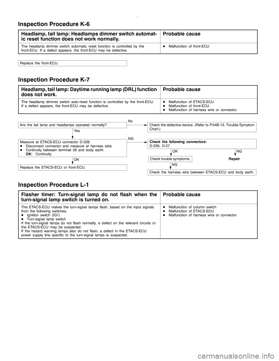
Inspection Procedure K-6
Headlamp, tail lamp: Headlamps dimmer switch automat-
ic reset function does not work normally.Probable cause
The headlamp dimmerswitch automatic reset function is controlled by the
front-ECU. If a defect appears, the front-ECU may be defective.DMalfunction of front-ECU
Replace the front-ECU.
Inspection Procedure K-7
Headlamp, tail lamp: Daytime running lamp (DRL) function
does not work.Probable cause
The headlamp dimmerswitch auto-reset function is controlled by the front-ECU.
If a defect appears, the front-ECU may be defective.DMalfunction of ETACS-ECU
DMalfunction of front-ECU
DMalfunction of harness wire or connector.
NoCheck the defective device. (Refer to P.54B-13, Trouble Symptom
Chart.)
Ye s
NG
NG
Repair
NG
Check the harness wire between ETACS-ECU and body earth.
OK
Replace the ETACS-ECU or front-ECU.
OK
Check trouble symptoms.
Check the following connectors:
D-226, D-27Measure at ETACS-ECU connector D-226.
DDisconnect connector and measure at harness side.
DContinuity between terminal 29 and body earth.
OK:Continuity
Are the tail lamp and headlamps operated normally?
Inspection Procedure L-1
Flasher timer: Turn-signal lamp do not flash when the
turn-signal lamp switch is turned on.Probable cause
The ETACS-ECU makes the turn-signal lamps flash, based on the input signals
from the following switches:
DIgnition switch (IG1)
DTurn-signal lampswitch
If the turn-signal lamps do not flash normally, a defect on the relevant circuits or
the ETACS-ECU may be suspected.
If the hazard warning lamps also do not flash, a defect in the ETACS-ECU
power supply line specific to the turn-signal lamps is suspected.DMalfunction of column switch
DMalfunction of ETACS-ECU
DMalfunction of harness wire or connector.
www.WorkshopManuals.co.uk
Purchased from www.WorkshopManuals.co.uk