2000 MITSUBISHI CARISMA automatic transmission
[x] Cancel search: automatic transmissionPage 213 of 280

FOR EMERGENCIES
8–13
Front
N25A200a
Towing with a rope
1. For vehicles with automatic transmis-
sion check the automatic transmis-
sion fluid level. (Refer to “Automatic
transmission fluid” on page 9–4.)
If the fluid level is low, transport the ve-
hicle with all wheels off the ground.
CAUTION
If the vehicle is out of automatic trans-
mission fluid, the transmission could
be damaged.
2. The towing hooks (A) are located as
shown in the illustrations. Attach the
tow rope to the towing hooks.
Rear
N25A057a
NOTE
(1) Using any part other than the desig-
nated towing hooks (A) could result in
damage to vehicle body.
(2) Use care that the towing rope is kept as
horizontal as possible.
An angled towing rope can damage the
vehicle body.
(3) Never attempt to tow out a ditched ve-
hicle because the towing rope cannot
be kept horizontal.
3. Turn the ignition switch to the “ACC” or
“ON” position to unlock the steering
wheel.
CAUTION
(1) As the engine is not running, the
brake booster and power steer-
ing pump do not operate. This
means higher brake depression
force and higher steering effort
are required. Therefore vehicle
operation is more difficult than
usual.
(2) Do not leave the key in the
“LOCK” position. If the key is re-
moved while driving, the steering
will be locked causing loss of
control.
4. Turn on the hazard warning lamps.
5. Move the gearshift lever (manual
transmission) or the selector lever (au-
tomatic transmission) to Neutral or the
“N” position.
6. During towing make sure that close
contact is maintained between the
drivers of both vehicles, and that the
vehicles travel at low speed. Avoid
abrupt starting or stopping which
might subject the vehicles to shock.
Page 215 of 280

FOR EMERGENCIES
8–15
Towing the vehicle by a tow truck
CAUTION
(1) This vehicle cannot be towed by
a tow truck using Type A equip-
ment to prevent the bumper from
deformation. If this vehicle is
towed, use Type B, Type C, Type
D or Type E equipment.
(2) In case the vehicle with automatic
transmission must be towed far-
ther than 30 km, transport the ve-
hicle with all wheels off the
ground (Type B or C) or with front
wheels off the ground (Type D).
(3) If the transmission is not operat-
ing, transport the vehicle with all
wheels off the ground (Type B or
C).
Towing with front wheels off the
ground (Type D)
Release the parking brake. Place the gear-
shift lever (manual transmission) or the se-
lector lever (automatic transmission) in the
“N” (NEUTRAL) position.
Towing with rear wheels off the
ground (Type E)
Place the gearshift lever (manual trans-
mission) or the selector lever (automatic
transmission) in the “N” (NEUTRAL) posi-
tion.
Turn the ignition key to the “ACC” position
and secure the steering wheel in a straight-
ahead position with a rope, etc.
Never place the ignition key in the “LOCK”
position. It is dangerous as the steering
wheel may lock.
Engine overheatingEN26A - Ub
If the water temperature gauge indication re-
mains in the overheating zone for a long
time, the engine may be overheating. If this
occurs, take the following corrective
measures :
1. Stop the vehicle in a safe place.
Page 218 of 280

FOR EMERGENCIES
8–18
CAUTION
Check the other vehicle. It must have
a 12-volt battery.
If the other system isn’t 12-volt, short-
ing can damage both vehicles.
2. You could be injured if the vehicles roll.
Set the parking brake firmly on each
vehicle. Put an automatic trans-
mission in “P” (PARK) or a manual
transmission in “N” (Neutral). Turn off
the ignition switch.
WARNING
Tu r n o f f t h e ignition on both vehicles
beforehand. Use care to make sure
that the cables or your clothes do not
get caught by the fan or drive belt.
Personal injury could result.
NOTE
Turn off all lamps, heater and other electrical
loads. This will avoid sparks and help save
both batteries.
3. Make sure battery electrolyte is at the
proper level.
Refer to “Battery” on page 9–7.
WARNING
If electrolyte fluid is not visible, or ap-
pears to be frozen, do not attempt
jump starting!
A battery might rupture or explode if
the temperature is below the freezing
point or if it is not filled to the proper
level.
Petrol-powered vehicles (1300 models)
N28A195a
4. Connect one end of one jumper cable
to the positive (+) terminal of the dis-
charged battery, and the other end to
the positive (+) terminal of the booster
battery.
5. Connect one end of the other jumper
cable to the negative (-) terminal of the
booster battery, and the other end to
the engine block of the vehicle with the
discharged battery at the point farthest
from the battery.
NOTE
Remove the cover before connecting the
jumper cable to the positive terminal of the
battery.
Page 222 of 280

FOR EMERGENCIES
8–22
CAUTION
(1) Do not smoke or have any other
open flame near the vehicle while
bleeding the fuel system.
(2) Be sure to carefully clean away
any water drained out, because
any fuel mixed with the water
could ignite and cause a fire.
What to do if the engine
speed becomes unstable
after the battery is replaced:
EN38B–P
If the engine speed becomes unstable after
the battery is replaced, reset the engine
using the following method:
1. Stop the vehicle in a safe place.
2. Place the gearshift lever (manual
transmission) in the ”N” (Neutral) or
the selector lever (automatic trans-
mission) in the ”P” (PARK) position.
Stop the engine.
3. Restart the engine.
4. Turn off the air conditioning (if so
equipped).
5. Allow the engine to warm up until the
needle in the water temperature
gauge stabilizes near the centre of the
gauge.
6. Stop and restart the engine.
7. Allow the engine to idle for approxi-
mately 10 minutes.
8. When the engine speed stabilizes, the
resetting procedure is complete.
NOTE
If the engine speed remains unstable after
the resetting procedure has been per-
formed, have the vehicle inspected by an
authorized MITSUBISHI dealer.
N09A030a
FusesEN09A - Na
Fuse block
To prevent damage to the electric system
due to short - circuiting or overloading, each
individual circuit is provided with a fuse.
There are fuse boxes in the passenger com-
partment and in the engine compartment.
The fuse box in the passenger compartment
is located in front of the driver’s seat as
shown in the illustration.
Page 239 of 280

Maintenance
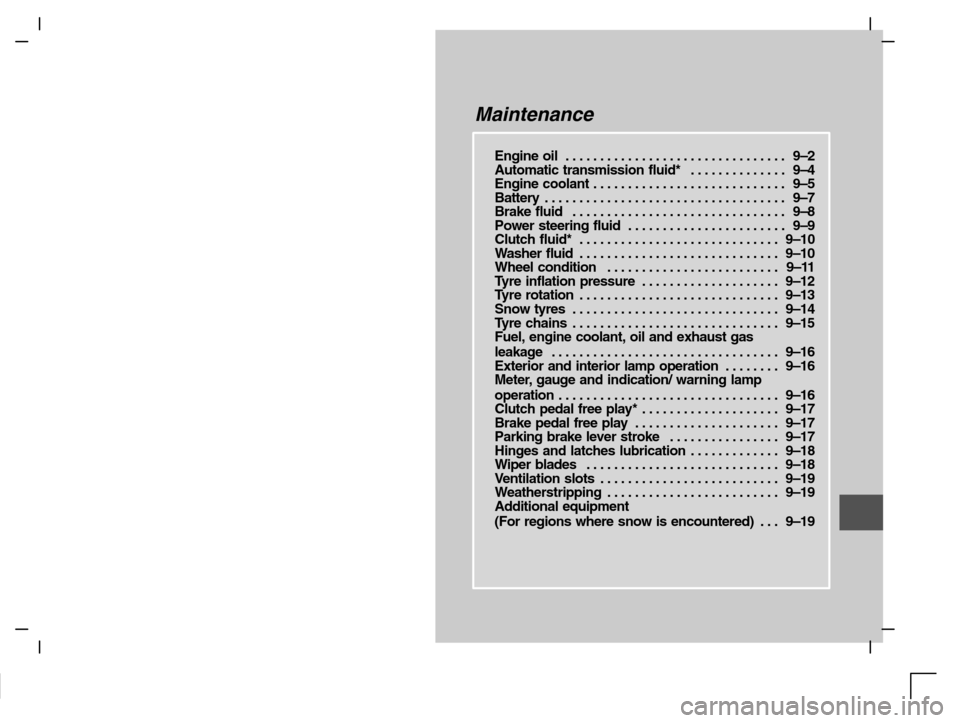
Engine oil 9–2. . . . . . . . . . . . . . . . . . . . . . . . . . . . . . . .
Automatic transmission fluid* 9–4. . . . . . . . . . . . . .
Engine coolant 9–5. . . . . . . . . . . . . . . . . . . . . . . . . . . .
Battery 9–7. . . . . . . . . . . . . . . . . . . . . . . . . . . . . . . . . . .
Brake fluid 9–8. . . . . . . . . . . . . . . . . . . . . . . . . . . . . . .
Power steering fluid 9–9. . . . . . . . . . . . . . . . . . . . . . .
Clutch fluid* 9–10. . . . . . . . . . . . . . . . . . . . . . . . . . . . .
Washer fluid 9–10. . . . . . . . . . . . . . . . . . . . . . . . . . . . .
Wheel condition 9–11. . . . . . . . . . . . . . . . . . . . . . . . .
Tyre inflation pressure 9–12. . . . . . . . . . . . . . . . . . . .
Tyre rotation 9–13. . . . . . . . . . . . . . . . . . . . . . . . . . . . .
Snow tyres 9–14. . . . . . . . . . . . . . . . . . . . . . . . . . . . . .
Tyre chains 9–15. . . . . . . . . . . . . . . . . . . . . . . . . . . . . .
Fuel, engine coolant, oil and exhaust gas
leakage 9–16. . . . . . . . . . . . . . . . . . . . . . . . . . . . . . . . .
Exterior and interior lamp operation 9–16. . . . . . . .
Meter, gauge and indication/ warning lamp
operation 9–16. . . . . . . . . . . . . . . . . . . . . . . . . . . . . . . .
Clutch pedal free play* 9–17. . . . . . . . . . . . . . . . . . . .
Brake pedal free play 9–17. . . . . . . . . . . . . . . . . . . . .
Parking brake lever stroke 9–17. . . . . . . . . . . . . . . .
Hinges and latches lubrication 9–18. . . . . . . . . . . . .
Wiper blades 9–18. . . . . . . . . . . . . . . . . . . . . . . . . . . .
Ventilation slots 9–19. . . . . . . . . . . . . . . . . . . . . . . . . .
Weatherstripping 9–19. . . . . . . . . . . . . . . . . . . . . . . . .
Additional equipment
(For regions where snow is encountered) 9–19. . .
Page 242 of 280

MAINTENANCE
9–4
Type 1
M03B029a
Selection of engine oil
(diesel-powered vehicles)
EM03BAKe
(1) Select engine oil of the proper SAE vis-
cosity number according to the atmos-
pheric temperature.
(2) Use engine oil conforming to the follow-
ing classification:
Ty p e 1 :ACEA classification:
“For service B2-96 or B3-96”
Ty p e 2 :API classification:
“For service CF”
NOTE
Use of additives is not recommended
since they may reduce the effectiveness of
additives already included in the engine
oil. It may result in failure of the mechani-
cally assembly.
Type 2
M03B030aM05A069a
Automatic transmission fluid*EM05AAH
The proper amount of automatic trans-
mission fluid is essential to the life and oper-
ation of the automatic transmission. Either in-
sufficient fluid or excessive fluid could cause
transmission trouble. The transmission fluid
filler port cap is equipped with a dipstick. Use
the following procedure to check the fluid
level.
1. Check the fluid level after the vehicle
has been driven enough to warm up
the transmission fluid.
2. Park the vehicle on a flat, level surface
and apply the parking brake.
Page 268 of 280

SPECIFICATIONS
10–10
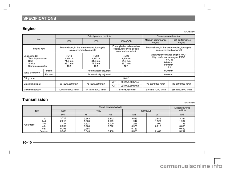
EngineEP01EMDb
Petrol-powered vehicleDiesel-powered vehicleItem130016001800 (GDI)Medium performanceHigh performance130016001800 (GDI)penginegpengine
Engine typeFour-cylinder, in line water-cooled, four-cycle
single overhead camshaftFour-cylinder, in line water-
cooled, four-cycle double
overhead camshaftFour-cylinder, in line water-cooled, four-cycle
single overhead camshaft
Engine model
Total displacement
Bore
Stroke
Compression ratio4G13
1,299 cc
71.0 mm
82.0 mm
10:14G92
1,597 cc
81.0 mm
77.5 mm
10:14G93
1,834 cc
81.0 mm
89.0 mm
12:1Medium performance engine: F9Q1
High performance engine: F9Q2
1,870 cc
80.0 mm
93.0 mm
19:1
Valve clearanceIntakeAutomatically adjusted0.20 mmValve clearanceExhaustAutomatically adjusted0.40 mm
Firing order1-3-4-2
Maximum output60 kW/5 000 r/min76 kW/6 000 r/minM/T90 kW/5,500 r/min75 kW/4 000 r/min85 kW/4 000 r/minMaximum output60 kW/5,000 r/min76 kW/6,000 r/minA/T92 kW/5,500 r/min75 kW/4,000 r/min85 kW/4,000 r/min
Maximum torque120 Nm/4,000 r/min141 Nm/4,500 r/min174 Nm/3,750 r/min215 Nm/3,250 r/min265 Nm/2,500 r/min
TransmissionEP01FMDa
Petrol-powered vehicleDiesel-poweredItem130016001800 (GDI)pvehicle
M/TM/TA/TM/TA/TM/T
Gear ratio
1st
2nd
3rd
4th
5th
Reverse3.727
2.047
1.321
0.966
0.794
3.5453.363
1.863
1.321
0.966
0.794
3.5452.842
1.529
1.000
0.712
–
2.4803.583
1.947
1.266
0.970
0.767
3.3632.842
1.529
1.000
0.712
–
2.4803.384
1.904
1.193
0.868
0.652
3.297
Page 274 of 280

SPECIFICATIONS
10–16
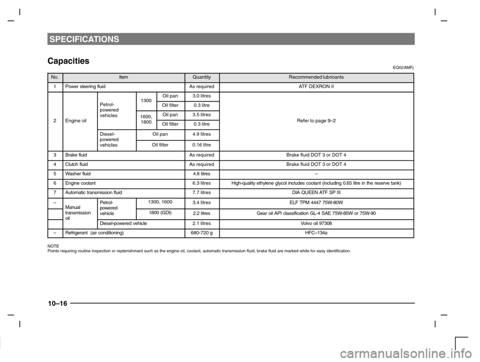
CapacitiesEQ02AMFj
No.ItemQuantityRecommended lubricants
1Power steering fluidAs requiredATF DEXRON II
1300Oil pan3.0 litres
Petrol-powered
1300Oil filter0.3 litre
2Engine oil
powered
vehicles1600,Oil pan3.5 litresRefer to page 9 22Engine oil1800Oil filter0.3 litreRefer to page 9–2
Diesel-poweredOil pan4.9 litrespowered
vehiclesOil filter0.16 litre
3Brake fluidAs requiredBrake fluid DOT 3 or DOT 4
4Clutch fluidAs requiredBrake fluid DOT 3 or DOT 4
5Washer fluid4.8 litres–
6Engine coolant6.3 litresHigh-quality ethylene glycol includes coolant (including 0.65 litre in the reserve tank)
7Automatic transmission fluid7.7 litresDIA QUEEN ATF SP III
–ManualPetrol-powered1300, 16003.4 litresELF TPM 4447 75W-80WManual
transmission
oil
powered
vehicle1800 (GDI)2.2 litresGear oil API classification GL-4 SAE 75W-85W or 75W-90oilDiesel-powered vehicle2.1 litresVolvo oil 97308
–Refrigerant (air conditioning)680-720 gHFC–134a
NOTE
Points requiring routine inspection or replenishment such as the engine oil, coolant, automatic transmission fluid, brake fluid are marked white for easy identification.