Page 42 of 280

SEATS AND SEATBELTS
3–14
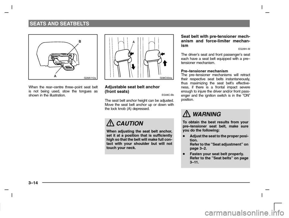
G28A112a
When the rear–centre three–point seat belt
is not being used, stow the tongues as
shown in the illustration.
G08C004a
Adjustable seat belt anchor
(front seats)
EG08C-Bb
The seat belt anchor height can be adjusted.
Move the seat belt anchor up or down with
the lock knob (A) depressed.
CAUTION
When adjusting the seat belt anchor,
set it at a position that is sufficiently
high so that the belt will make full con-
tact with your shoulder but will not
touch your neck.
Seat belt with pre-tensioner mech-
anism and force-limiter mechan-
ism
EG28H–M
The driver’s seat and front passenger’s seat
each have a seat belt equipped with a pre–
tensioner mechanism.
Pre–tensioner mechanismThe pre–tensioner mechanisms will retract
their respective seat belts instantaneously,
thus maximizing the seat belt’s effective-
ness, if there is a frontal impact severe
enough to injure the driver and/or front pass-
enger and the ignition switch is in the ”ON”
position.
WARNING
To o btain the best results from your
pre–tensioner seat belt, make sure
you do the following:
�Adjust the seat to the proper posi-
tion.
Refer to the ”Seat adjustment” on
page 3–2.
�Fasten your seat belt properly.
Refer to the ”Seat belts” on page
3–11.
Page 54 of 280

SEATS AND SEATBELTS
3–26
When the impact sensors detect an impact
of sufficient frontal or side force, an auto-
mated circuit ignites materials in the inflator
to generate gas and inflate the air bags. The
air bags deployment produces a sudden,
loud noise, and releases some smoke and
powder, but these conditions are not injuri-
ous, and do not indicate a fire in the vehicle.
People with respiratory problems may feel
some temporary irritation from chemicals
used to produce the deployment; open the
windows after air bag deployment, if safe to
do so.
The air bags deflate very rapidly after de-
ployment, so there is little danger of ob-
scured vision.
The time required from the sensors detecting
an impact to deflation of the air bags after de-
ployment is shorter than a blink of an eye.
CAUTION
Air bags are inflated at an extremely
rapid speed. In certain situations,
contact with inflating air bags can re-
sult in light cuts, bruises, and the like.
G28G012a
Driver’s and passenger’s front air
bag system
EG29C-A
The driver’s air bag is located under the
padded cover in the middle of the steering
wheel. The front passenger air bag is con-
tained in the instrument panel above the
glove box.
The driver air bag and the front passenger air
bag are designed to inflate at the same time
even if the passenger seat is not occupied.
Page 56 of 280
SEATS AND SEATBELTS
3–28
G28L086d
The front air bags MAY NOT DEPLOY when...
With certain types of frontal collisions, the ve-
hicle’s body structure is designed to absorb
the shock to help protect the occupants from
harm. (The vehicle body’s front area may de-
form significantly as it absorbs the impact.)
Under such circumstances, the front air bags
may not deploy irrespective of the deforma-
tion and damage to the vehicle body.
Examples of some typical conditions are
shown in the illustration:1-Collision with a utility pole, tree or
other narrow object
2-Vehicle slides under the rear body of a
truck
3-Oblique frontal impactsBecause the front air bags do not protect the
occupant in all types of frontal collisions, be
sure to always properly wear your seat belts.
Page 61 of 280
SEATS AND SEATBELTS
3–33
G28L089d
The side air bags MAY NOT DEPLOY when...
With certain types of side collisions, the ve-
hicle’s body structure is designed to absorb
the shock to help protect the occupants from
harm. (The vehicle body’s side area may de-
form significantly as it absorbs the impact.)
Under such circumstances, the side air bags
may not deploy irrespective of the deforma-
tion and damage to the vehicle body.
Examples of some typical conditions are
shown in the illustration:1-Side impacts in an area away from the
passenger compartment
2-Motorcycle or other similar small ve-
hicle collides with the side of the ve-
hicle
3-Collision with a utility pole, tree or
other narrow object
4-Oblique side impacts
5-Vehicle rolls onto its side or roofBecause the side air bags do not protect the
occupant in all types of side collisions, be
sure to always properly wear your seat belts.
Page 70 of 280
INSTRUMENTS AND CONTROLS
4–4
NOTE
(1) Display A and B each have a maximum
distance of 999.9 mile (km).
(2) When disconnecting the battery ter-
minal for a long time, the memory of trip-
meter display A and B are cleared, and
the display returns to “0”.
D04A067a
TachometerED04A-Ac
The tachometer indicates the engine speed
(r/min). The tachometer can help you obtain
more economical driving and also warns you
of excessive engine speeds.
CAUTION
During travel, watch the tachometer
making sure that the engine speed in-
dication does not rise to the red zone
(excessive engine rpm).
Type 1
D05A020a
Fuel gaugeED15A-Ea
The fuel gauge indicates the fuel level in the
fuel tank irrespective of the ignition switch
position.
0- Empty
1- Full
CAUTION
Do not drive with an extremely low
fuel level; running out of fuel could
cause damage to the catalytic con-
verter.
Page 76 of 280

INSTRUMENTS AND CONTROLS
4–10
CAUTION
(3) If the lamp illuminates or flashes while the
engine is running, avoid driving at high
speeds and have the system checked at
an authorized MITSUBISHI dealer.
During vehicle operation with the lamp il-
luminated or flashing, the vehicle may not
accelerate when you depress the acceler-
ator pedal.
When the vehicle is stationary with the
lamp illuminated or flashing, you must de-
press the brake pedal more firmly than
usual since the engine idling speed is
higher than usual and the vehicle with an
automatic transmission has a stronger
tendency to creep forward.
NOTE
The engine electronic control module accommodat-
ing the onboard diagnostic system has various fault
data (especially about the exhaust emission) stored.
This data will be erased if a battery cable is discon-
nected, which will make rapid diagnosis difficult. Do
not disconnect a battery cable when the check engine
indication lamp is ON.
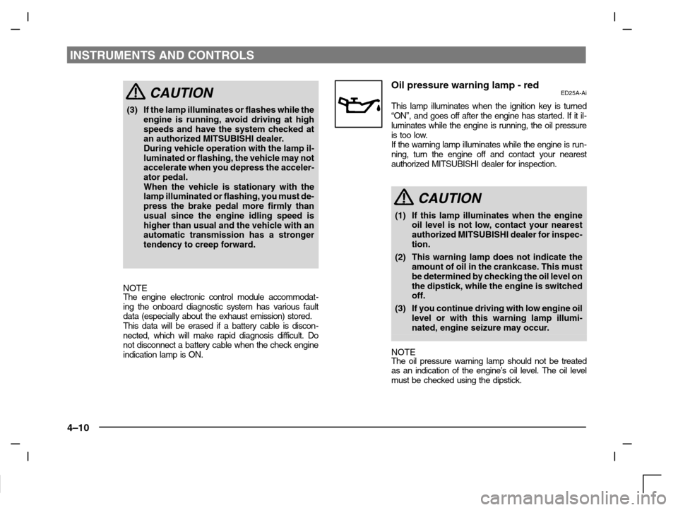
Oil pressure warning lamp - redED25A-Ai
This lamp illuminates when the ignition key is turned
“ON”, and goes off after the engine has started. If it il-
luminates while the engine is running, the oil pressure
is too low.
If the warning lamp illuminates while the engine is run-
ning, turn the engine off and contact your nearest
authorized MITSUBISHI dealer for inspection.
CAUTION
(1) If this lamp illuminates when the engine
oil level is not low, contact your nearest
authorized MITSUBISHI dealer for inspec-
tion.
(2) This warning lamp does not indicate the
amount of oil in the crankcase. This must
be determined by checking the oil level on
the dipstick, while the engine is switched
off.
(3) If you continue driving with low engine oil
level or with this warning lamp illumi-
nated, engine seizure may occur.
NOTE
The oil pressure warning lamp should not be treated
as an indication of the engine’s oil level. The oil level
must be checked using the dipstick.
Page 102 of 280

STARTING AND DRIVING
5–2
Running-in
recommendations
EA01AMKi
During the running-in period for the first
1,000 km, it is advisable to drive your new
vehicle using the following precautions as a
guideline to aid long life as well as future
economy and performance.
(1) Do not race the engine at high speeds.
(2) Avoid rapid starting, accelerating, brak-
ing and prolonged high-speed running.
(3) Keep to the running-in speed limit
shown below.
Please note that the legal speed limits
displayed must be adhered to.
(4) Do not exceed loading limits.
(5) Refrain from towing a trailer.
Ve h i c les with manual transmissionkm/h
Speed limit
DrivePetrol-powered vehicleDiesel-range
130016001800
(GDI)powered
vehicle
1st25353025
2nd50606045
3rd80909070
4th105120120100
5th130150155135
Vehicles with automatic trans-
mission INVECS-II 4A/T
km/h
Drive rangeSpeed limitDrive range1600
“L” (LOW)30
“2” (SECOND)70
“3” (THIRD)105
“D” (DRIVE)120
Ve h i c les with automatic trans-
mission INVECS-II
Sport Mode 4A/T
km/h
Drive rangeSpeed limit
1st30
2nd80
3rd120
4th130
Page 104 of 280

STARTING AND DRIVING
5–4
C20A132a
RHD
C20A162a
A- Remove
B- Close
3. Open the fuel tank filler tube by slowly
turning the cap anticlockwise.
NOTE
Put the fuel tank cap on the cap holder (C)
while refueling.
CAUTION
Since the fuel system may be under
pressure, remove the fuel tank filler
tube cap slowly. This relieves any
pressure or vacuum that might have
built up in the fuel tank. If the cap is
venting vapor or if you hear a hissing
sound, wait until it stops before re-
moving the cap. Otherwise, fuel may
spray out, injuring you or others.
4. To fill with fuel correctly depends main-
ly on correct handling of the fuel filler
gun. Do not tilt the gun. Insert the gun
in the tank port as far as it goes.
CAUTION
Petrol–powered vehicles have a label
located on the fuel tank filler lid that
states, ”UNLEADED FUEL ONLY”.
The vehicle also has a fuel tank filler
tube especially designed to accept
the smaller diameter unleaded petrol
dispensing nozzles only.
If the tank cap must be replaced, use
only a MITSUBISHI original part
specified for your vehicle.