Page 159 of 273

156 Driving instructions
Te ch n ica l
data Instruments
and controlsOperationDrivingInstrument
cluster displayPractical hints Car care Index
Caution!
When driving down long and steep grades, relieve the
load on the brakes by shifting into a lower gear to use
the engine’s braking power. This helps prevent
overheating of the brakes and reduces brake pad wear.
After hard braking, it is advisable to drive on for some
time, rather than immediately parking, so the air stream
will cool down the brakes faster.
Driving off
Apply the service brakes to test them briefly after
driving off. Perform this procedure only when the road
is clear of other traffic.
Warm up the engine smoothly. Do not place full load on
the engine until the operating temperature has been
reached.
W hen sta rting of f on a sl ippery surfa ce, d o not al low one
drive wheel to spin for an extended period with the ESP
switched off. Doing so may cause serious damage to the
drive train which is not covered by the Mercedes-Benz
Limited Warranty.Parking
Wa r n i n g !
To reduce the risk of personal injury as a result of
vehicle movement, before
turning off the engine
and leaving the vehicle, always:
1. Keep right foot on the service brake pedal.
2. Firmly engage parking brake.
3. Move the selector lever to position “P”
(manual transmission: first or reverse gear).
4. Slowly release the service brake pedal.
5. Turn front wheels towards the road curb.
6. Turn the key to steering lock position 0 and
remove.
7. Take the key and lock vehicle when leaving.
Page 171 of 273

168 Driving systems
Te ch n ica l
data Instruments
and controlsOperationDrivingInstrument
cluster displayPractical hints Car care Index
Antilock brake system (ABS)
Important!
The ABS improves steering control of the vehicle during
hard braking maneuvers.
The ABS prevents the wheels from locking up above a
vehicle speed of approximately 5 mph (8 km / h)
independent of road surface conditions.At the instant one of the wheels is about to lock up, a
slight pulsation can be felt in the brake pedal,
indicating that the ABS is in the regulating mode. Keep
firm and steady pressure on the brake pedal while
experiencing the pulsation.
Continuous steady brake pedal pressure results in
applying the advantages of the ABS, namely braking
power and ability to steer the vehicle.
In the case of an emergency brake maneuver keep
continuous full pressure on the brake pedal. In this
manner only can the ABS be most effective.
On slippery road surfaces, the ABS will respond even
with light brake pedal pressure because of the
increased likelihood of locking wheels. The pulsating
brake pedal can be an indication of hazardous road
conditions and functions as a reminder to take extra
care while driving.
Wa r n i n g !
Do not pump the brake pedal, rather use firm,
steady brake pedal pressure. Pumping the brake
pedal defeats the purpose for ABS and significantly
reduces braking effectiveness.
Page 174 of 273

171 Driving systems
Te ch n ica l
data Instruments
and controlsOperationDrivingInstrument
cluster displayPractical hints Car care Index Notes:
Th e m alf unction indicator l amp for t he ESP is combined
with that of the BAS.
The yellow BAS / ESP malfunction indicator lamp in the
instrument cluster and the yellow ESP warning
lampv in the speedometer dial come on with the
key in steering lock position 2. They should go out with
the engine running.
If the BAS / ESP malfunction indicator lamp comes on
continuously with the engine running, a malfunction
has been detected in either system. Only partial engine
output will be available.
If the BAS malfunctions, the brake system functions in
the usual manner, but without BAS.
Have the BAS or ESP checked at your authorized
Mercedes-Benz Center as soon as possible.
With the ABS malfunctioning, the ESP is also switched
off.Driving the vehicle with varied size tires will cause the
wheels to rotate at different speeds, therefore the ESP
may activate (yellow ESP warning lamp in speedometer
dial comes on). For this reason, all wheels, including the
spare wheel, must have the same tire size.
When testing the parking brake on a brake test
dynamometer, the engine must be shut off. Otherwise,
the ESP will immediately be engaged and will apply the
rear wheel brakes.
In winter operation, the maximum effectiveness of the
ESP is only achieved with Mercedes-Benz recommended
M+S rated radial-ply tires and / or snow chains.
Synchronizing ESP
If the power supply was interrupted (battery
disconnected or empty), the BAS / ESP malfunction
indicator lamp may be illuminated with the engine
running.
Turn steering wheel completely to the left and then to
the right. The BAS / ESP malfunction indicator lamp
should go out.
Page 187 of 273

184 Malfunction and indicator lamps
Te ch n ica l
data Instruments
and controlsOperation DrivingInstrument
cluster displayPractical hints Car care Index
Low engine oil level warning lamp
With the key in steering lock position 2, the
oil level warning lamp comes on. It should
go out immediately when the engine is
running.
If the warning lamp does not go out after starting the
engine, or comes on with the engine running and at
operating temperature, the engine oil level has dropped
to approximately the minimum mark on the dipstick.
When this occurs, the warning lamp will first come on
intermittently and then stay on if the oil level drops
further.
If no leaks are noted, continue to drive to the nearest
service station where the engine oil should be topped to
the “full” mark on the dipstick with an approved oil.
The low engine oil level warning light should not be
ignored. Extended driving with the light illuminated
could result in serious engine damage that is not
covered by the Mercedes-Benz Limited Warranty.
In addition to the warning lamp, the engine oil level
should be periodically checked with the dipstick, for
example during a fuel stop, or before a long trip, see
page 193.Charge indicator lamp
Should the charge indicator lamp fail to
come on prior to starting when the key is in
ste ering lock position 2 or sh ou ld it fa il to g o
out after starting or during operation, this indicates a
malfunction which must be repaired immediately at an
authorized Mercedes-Benz Center.
If t he charg e ind ica tor l amp comes on, or a l oss of power
steering assistance is noticeable while the engine is
running, this may indicate that one of the two poly-V-
belts has broken. Should this condition occur, the poly-
V-belt mu st be replac ed before continuing to operate t he
vehicle. Otherwise, the engine may overheat due to an
inoperative water pump which may result in damage to
the engine.
Do not continue to drive the vehicle with the charge
indicator lamp illuminated. Doing so could result in
serious engine damage that is not covered by the
Mercedes-Benz Limited Warranty.
Page 218 of 273

215 Towing the vehicle
Te ch n ica l
data Instruments
and controlsOperation DrivingInstrument
cluster displayPractical hintsCar care Index Sport Package
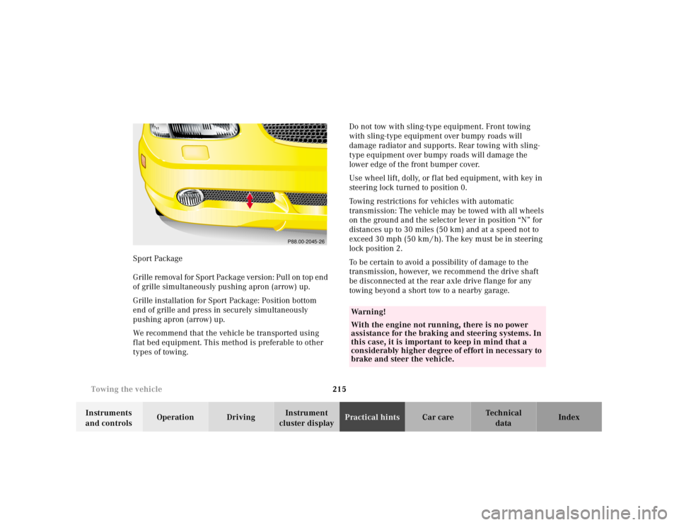
G r il l e re m ova l f or S p or t Pa cka g e v e rs i on : P u l l on t op e n d
of grille simultaneously pushing apron (arrow) up.
Grille installation for Sport Package: Position bottom
end of grille and press in securely simultaneously
pushing apron (arrow) up.
We recommend that the vehicle be transported using
f lat bed equipment. This method is preferable to other
types of towing.Do not tow with sling-type equipment. Front towing
with sling-type equipment over bumpy roads will
damage radiator and supports. Rear towing with sling-
type equipment over bumpy roads will damage the
lower edge of the front bumper cover.
Use wheel lift, dolly, or f lat bed equipment, with key in
steering lock turned to position 0.
Towing restrictions for vehicles with automatic
transmission: The vehicle may be towed with all wheels
on the ground and the selector lever in position “N” for
distances up to 30 miles (50 km) and at a speed not to
exceed 30 mph (50 km / h). The key must be in steering
lock position 2.
To be certain to avoid a possibility of damage to the
transmission, however, we recommend the drive shaft
be disconnected at the rear axle drive f lange for any
towing beyond a short tow to a nearby garage.
P88.00-2045-26
Wa r n i n g !
With the engine not running, there is no power
assistance for the braking and steering systems. In
this case, it is important to keep in mind that a
considerably higher degree of effort in necessary to
brake and steer the vehicle.
Page 236 of 273

233 Contents - Vehicle care
Te ch n ica l
data Instruments
and controlsOperation DrivingInstrument
cluster displayPractical hintsCar careIndex
Vehicle careCleaning and care
of the vehicle .............................234
Power washer ..............................235
Paintwork, painted body
components .................................235
Tar stains .....................................235
Engine cleaning ..........................236
Vehicle washing .........................236
Headlamps, taillamps,
turn signal lenses ......................237
Window cleaning ........................237Rear window cleaning .............. 237
Wiper blades .............................. 238
Light alloy wheels ..................... 238
Instrument cluster ..................... 238
Steering wheel and
gear selector lever ..................... 239
Cup holder .................................. 239
Hard plastic trim items ............. 239
Plastic and rubber parts ........... 239
Headliner and
shelf behind roll bars ................ 239
Upholstery .................................. 239
Seat belts ..................................... 240
Page 248 of 273
245 Technical data
Te ch n ica l
data Instruments
and controlsOperation DrivingInstrument
cluster displayPractical hints Car care Index Layout of poly-V-belt drive
SLK 230 Kompressor
routing, belt I
The engine is equipped with two poly-V-belts.
1Crankshaft
2Air conditioner compressor
3Power steering pump
4Coolant pumpSLK 230 Kompressor
routing, belt II
For dimensions of the poly-V-belts, see page 248.
5Idler pulley
6Generator (alternator)
7Idler pulley
8Idler pulley
9Supercharger
P13.20-2007-26
9
6
8
7
4
1
5
32
5
32
9
6
8
4
1
7
P13.20-2008-26
Page 249 of 273
246 Technical data
Te ch n ica l
data Instruments
and controlsOperation DrivingInstrument
cluster displayPractical hints Car care Index
SLK 230 Kompressor
routing combined, belts I and II1Crankshaft
2Air conditioner compressor
3Power steering pump
4Coolant pump
5Idler pulley
6Generator (alternator)
7Idler pulley
8Idler pulley
9Supercharger
9
6
8
7
4
1
5
32P13.20-2009-26