2000 MERCEDES-BENZ CLK430 airbag off
[x] Cancel search: airbag offPage 5 of 299

Instrument cluster displayBRAKE FLUID 217 Coolant level 236
PARKING BRAKE 218 Adding coolant 237
Malfunction and indicator lamps in the
instrument cluster 208ENGINE FAN 218 Windshield washer / headlamp
clean.system 238
On-board diagnostic systemCheck engine malfunction indicator lamp
208COOLANT (coolant level) 219 Windshield and headlamp
washer fluid mixing ratio 238
Brake warning lamp 209 COOLANT (coolant temp.) 220 Wheels 239
Supplemental restraint system STEER. WHEEL ADJUST. 221 Tire replacement 239
(SRS) indicator lamp 210 LIGHT SENSOR 221 Rotating wheels 240
Fuel reserve and fuel cap LIGHTING SYSTEM 222 Spare wheel 241
placement warning 210 WASHER FLUID 223 Changing wheels 242
Electronic stability program(ESP) OIL TEMP. (engine oil temperature) 224 Tire inflation pressure 247
warning lamp 211 ENGINE OIL LEVEL 224 Battery 249
BAS/ESP malfunction indicator lamp 211 ELEC. STABIL. PROG. (Electronic Jump starting 251
ABS malfunction indicator lamp 211 stability program) 226 Towing the vehicle 253
Telescoping steering column – Transmission selector lever,
indicator lamp 212
Practical hintsmanually unlocking 255
Seat belt warning lamp 212 Bulbs 256
Malfunction and indicator lamps in the First aid kit 228 Adjusting headlamp aim 261
center console 212 Shelf below rear window 228 Changing batteries in the
AIRBAG OFF indicator lamp 212 Stowing things in the vehicle 228 electronic main key 264
Roll bar warning lamp 221 Spare wheel, vehicle tools, storage Synchronizing remote control 266
Malfunction and warning messages in compartment 229 Emergency operation of
the multifunction display 213 Vehicle jack 230 sliding/pop-up roof 267
DISPLAY DEFECTIVE 214 Fuses 231
Manual release for fuel filler flap
268
BATTERY/ALTERNATOR 215 Hood 233 Replacing wiper blade insert 268
ABS-SYSTEM 216 Checking engine oil level 234 Trunk lamp 270
BRAKE ASSIST 216 Automatic transmission fluid level 236 Roof rack 270
BRAKE LINING WEAR 217
5
Page 20 of 299
Instruments and controls
Te ch n ica l
data Instruments
and controlsOperation DrivingInstrument
cluster displayPractical hints Car care Index
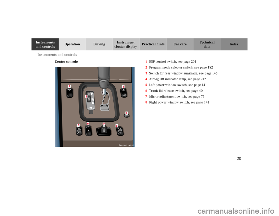
Center console1ESP control switch, see page
201
2Program mode selector switch, see page
182
3Switch for rear window sunshade, see page 146
4Airbag Off indicator lamp, see page 212
5Left power window switch, see page 141
6Trunk lid release switch, see page 40
7Mirror adjustment switch, see page 75
8Right power window switch, see page 141
P68.10-2192-27
2
5
1
6
7
8
43
20
Page 59 of 299
Restraint systems
Te ch n ica l
data Instruments
and controlsOperationDrivingInstrument
cluster displayPractical hints Car care Index Unfastening of seat belts
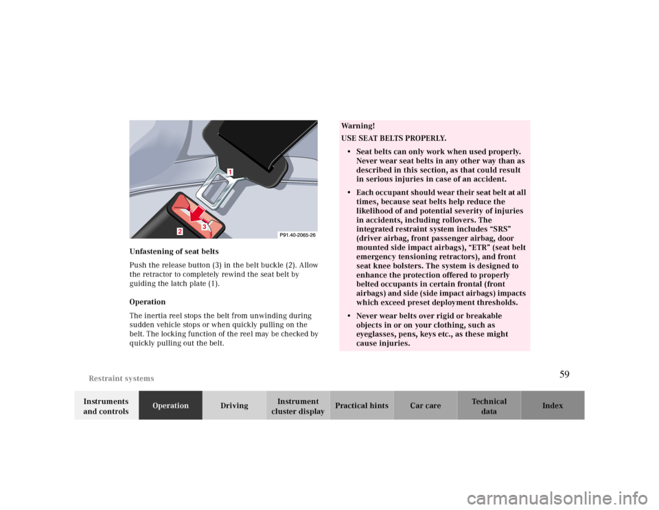
Push the release button (3) in the belt buckle (2). Allow
the retractor to completely rewind the seat belt by
guiding the latch plate (1).
Operation
The inertia reel stops the belt from unwinding during
sudden vehicle stops or when quickly pulling on the
belt. The locking function of the reel may be checked by
quickly pulling out the belt.
1
2
3
Wa r n i n g !
USE SEAT BELTS PROPERLY.• Seat belts can only work when used properly.
Never wear seat belts in any other way than as
described in this section, as that could result
in serious injuries in case of an accident.• Each occupant should wear their seat belt at all
times, because seat belts help reduce the
likelihood of and potential severity of injuries
in accidents, including rollovers. The
integrated restraint system includes “SRS”
(driver airbag, front passenger airbag, door
mounted side impact airbags), “ETR” (seat belt
emergency tensioning retractors), and front
seat knee bolsters. The system is designed to
enhance the protection offered to properly
belted occupants in certain frontal (front
airbags) and side (side impact airbags) impacts
which exceed preset deployment thresholds. • Never wear belts over rigid or breakable
objects in or on your clothing, such as
eyeglasses, pens, keys etc., as these might
cause injuries.
59
Page 80 of 299
Instrument cluster
Te ch n ica l
data Instruments
and controlsOperationDrivingInstrument
cluster displayPractical hints Car care Index
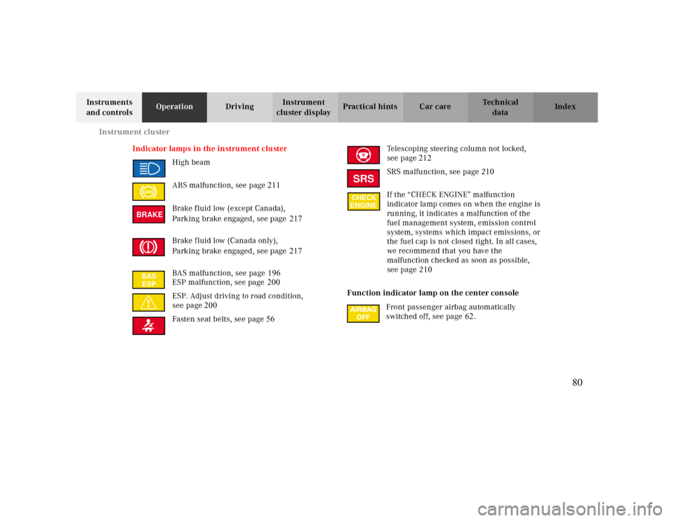
Indicator lamps in the instrument cluster
High beam
ABS malfunction, see page 211
Brake fluid low (except Canada),
Parking brake engaged, see page 217
Brake fluid low (Canada only),
Parking brake engaged, see page 217
BAS malfunction, see page 196
ESP malfunction, see page200
ESP. Adjust driving to road condition,
see page200
Fasten seat belts, see page56Telescoping steering column not locked,
see page212
SRS malfunction, see page 210
If the “CHECK ENGINE” malfunction
indicator lamp comes on when the engine is
running, it indicates a malfunction of the
fuel management system, emission control
system, systems which impact emissions, or
the fuel cap is not closed tight. In all cases,
we recommend that you have the
malfunction checked as soon as possible,
see page 210
Function indicator lamp on the center console
Front passenger airbag automatically
switched off, see page 62.
ABSBRAKEBAS
ESP
SRSCHECK
ENGINE
80
Page 168 of 299
Tele Aid
Te ch n ica l
data Instruments
and controlsOperationDrivingInstrument
cluster displayPractical hints Car care Index In the event of an ETR or airbag deployment, if the
system cannot connect to the Emergency Response
Center, it will attempt to contact 9-1-1. Close the
cover (1) after the emergency call is concluded.
Wa r n i n g !
If you feel at any way in jeopardy when in the
vehicle (e.g. smoke or fire in the vehicle, vehicle in
a dangerous road location), please do not wait for
voice contact after you have pressed the emergency
button. Carefully leave the vehicle and move to a
safe location. The Response Center will
automatically contact local emergency officials
with the vehicle’s approximate location
Roadside Assistance button •
Located below the center armrest cover is the Roadside
Assistance button•. Pressing and holding the
button (for longer than 2 seconds) will initiate a call to a
Mercedes-Benz Roadside Assistance dispatcher. The
button will flash while the call is in progress. The
message “ROADSIDE ASSISTANCE – CONNECTING
CALL” will appear in the multifunction display. When the connection is established, the message “ROADSIDE
ASSISTANCE – CALL CONNECTED” appears in the
multifunction display. The Tele Aid system will transmit
data generating the vehicle identification number,
model, color and location (subject to availability of
cellular and GPS signals).
A voice connection between the Roadside Assistance
dispatcher and the occupants of the vehicle will be
established. The nature of the need for assistance
can then be described.
.
For services such as labor and/or towing charges
may apply.Refer to the Roadside Assistance manual
for moreinformation. Sign and Drive services: Services such as jump start,
a few gallons of fuel or the replacement of a f lat tire
with the vehicle spare tire are obtainable
168
Page 207 of 299

Instrument cluster display
BRAKE FLUID 217
PARKING BRAKE 218
Malfunction and indicator lamps in the
instrument cluster 208ENGINE FAN 218
On-board diagnostic system
Check engine malfunction indicator lamp
208COOLANT (coolant level) 219
Brake warning lamp 209 COOLANT (coolant temp.) 220
Supplemental restraint system STEER. WHEEL ADJUST. 221
(SRS) indicator lamp 210 LIGHT SENSOR 221
Fuel reserve and fuel cap LIGHTING SYSTEM 222
placement warning 210 WASHER FLUID 223
Electronic stability program(ESP) OIL TEMP. (engine oil temperature) 224
warning lamp 211 ENGINE OIL LEVEL 224
BAS/ESP malfunction indicator lamp 211 ELEC. STABIL. PROG. (Electronic
ABS malfunction indicator lamp 211 stability program) 226
Telescoping steering column –
indicator lamp 212
Seat belt warning lamp 212
Malfunction and indicator lamps in the
center console 212
AIRBAG OFF indicator lamp 212
Roll bar warning lamp 221
Malfunction and warning messages in
the multifunction display 213
DISPLAY DEFECTIVE 214
BATTERY/ALTERNATOR 215
ABS-SYSTEM 216
BRAKE ASSIST 216
BRAKE LINING WEAR 217
207
Page 212 of 299
Malfunction and indicator lamps
Te ch n ica l
data Instruments
and controlsOperation DrivingInstrument
cluster displayPractical hints Car care Index
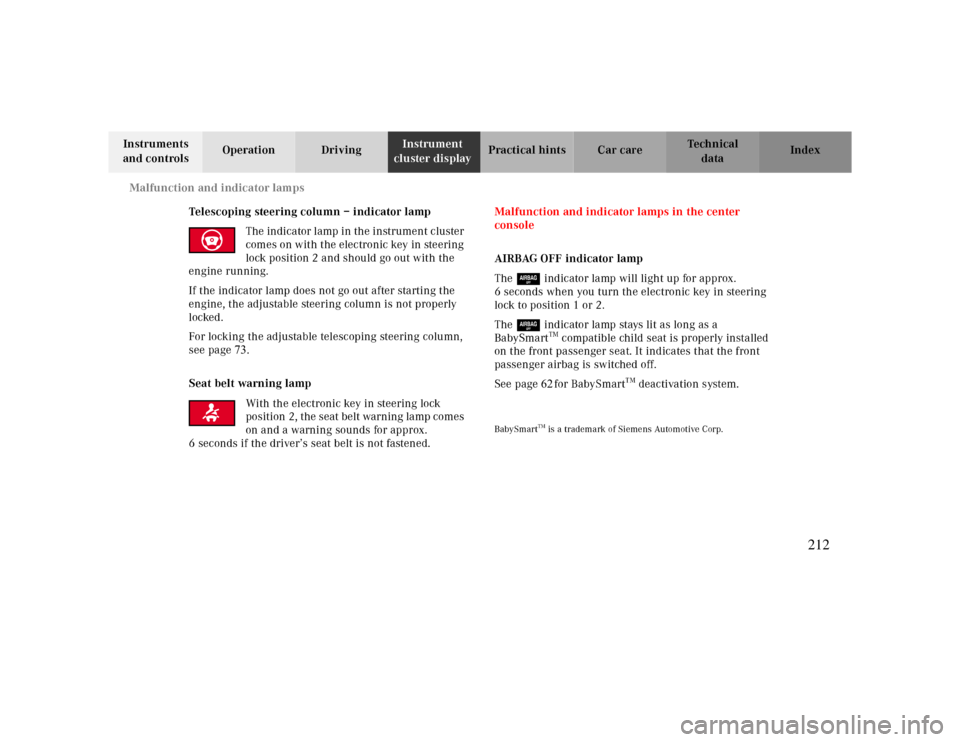
Telescoping steering column – indicator lamp
The indicator lamp in the instrument cluster
comes on with the electronic key in steering
lock position 2 and should go out with the
engine running.
If the indicator lamp does not go out after starting the
engine, the adjustable steering column is not properly
locked.
For locking the adjustable telescoping steering column,
see page
73.
Seat belt warning lamp
With the electronic key in steering lock
position 2, the seat belt warning lamp comes
on and a warning sounds for approx.
6 seconds if the driver’s seat belt is not fastened.Malfunction and indicator lamps in the center
console
AIRBAG OFF indicator lamp
The 7 indicator lamp will light up for approx.
6 seconds when you turn the electronic key in steering
lock to position 1 or 2.
The 7 indicator lamp stays lit as long as a
BabySmart
TM compatible child seat is properly installed
on the front passenger seat. It indicates that the front
passenger airbag is switched off.
See page62for BabySmart
TM deac tiva tio n system.
BabySmart
TM is a trademark of Siemens Automotive Corp.
212
Page 291 of 299
IndexAABS (Antilock brake system)………………………….198ABS-SYSTEM - malfunction and
warning messages .................................................. 216
Adjusting headlamp aim ........................................... .261Adjusting telescoping steering column ........................73Air conditioner refrigerant........................................ 285Airbag OFF indicator lamp ..........................................212Airbags ........................................................................64Antilock brake system (ABS) ...................................... 198
Malfunction indicator lamp ....................................211
Antitheft alarm system..................................................41Aquaplaning .............................................................. .188Ashtray
Center console, front ..............................................150Rear seats ..............................................................151
Audio system
Anti-theft system ....................................................125Button and soft key operation ................................126Cassette mode.........................................................131CD changer ............................................................135
CD mode................................................................ 134Operating and display elements ............................. 124Operating safety .................................................... 123Operation .............................................................. 127Operation Audio and telephone .............................. 123Radio mode ........................................................... 129Telephone operation .............................................. 138
Audio systems ............................................................. 89
Cassette player ........................................................ 91CD player................................................................. 90Radio ....................................................................... 89
Automatic climate control............................................ 116
Air distribution ..................................................... .120Air recirculation .................................................... .121Air volume ............................................................ .120Basic setting.......................................................... 118Defogging windows ................................................ 119Defrosting............................................................... 119Display and controls ............................................... 118Dust filter .............................................................. .122Economy................................................................. 119Rear window defroster ........................................... .120Residual engine heat utilization (REST) ................ .121Special settings....................................................... 119
291