Page 16 of 224

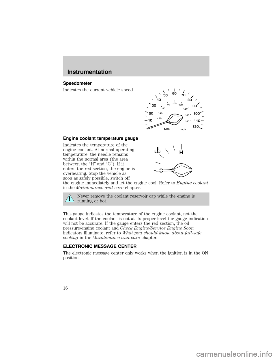
Speedometer
Indicates the current vehicle speed.
Engine coolant temperature gauge
Indicates the temperature of the
engine coolant. At normal operating
temperature, the needle remains
within the normal area (the area
between the ªHº and ªCº). If it
enters the red section, the engine is
overheating. Stop the vehicle as
soon as safely possible, switch off
the engine immediately and let the engine cool. Refer toEngine coolant
in theMaintenance and carechapter.
Never remove the coolant reservoir cap while the engine is
running or hot.
This gauge indicates the temperature of the engine coolant, not the
coolant level. If the coolant is not at its proper level the gauge indication
will not be accurate. If the gauge enters the red section, the oil
pressure/engine coolant andCheck Engine/Service Engine Soon
indicators illuminate, refer toWhat you should know about fail-safe
coolingin theMaintenance and carechapter.
ELECTRONIC MESSAGE CENTER
The electronic message center only works when the ignition is in the ON
position.
10
2030405060
70
80
90
100
120206080
40100
120
160 140
180
MPHkm/h
110
H
Instrumentation
16
Page 26 of 224

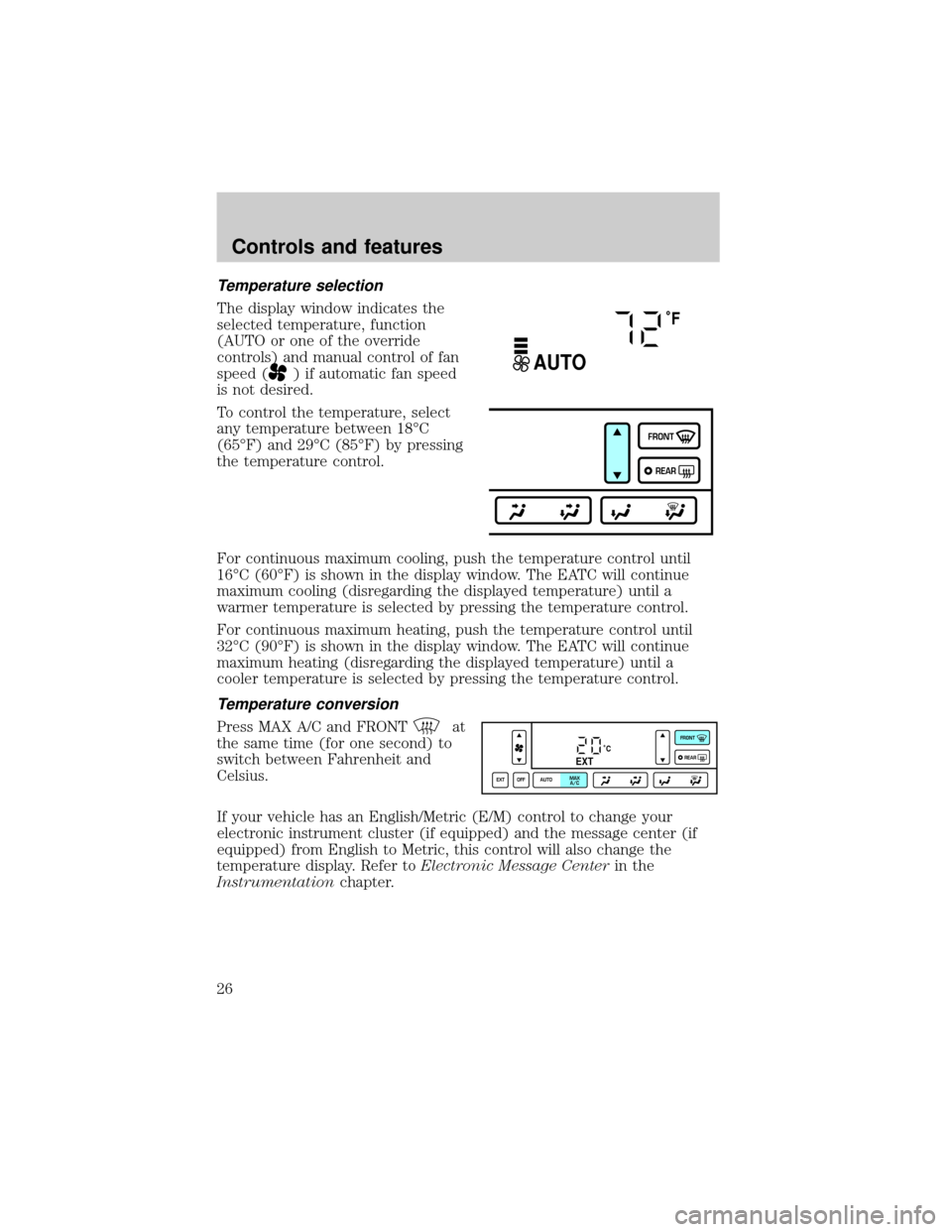
Temperature selection
The display window indicates the
selected temperature, function
(AUTO or one of the override
controls) and manual control of fan
speed (
) if automatic fan speed
is not desired.
To control the temperature, select
any temperature between 18ÉC
(65ÉF) and 29ÉC (85ÉF) by pressing
the temperature control.
For continuous maximum cooling, push the temperature control until
16ÉC (60ÉF) is shown in the display window. The EATC will continue
maximum cooling (disregarding the displayed temperature) until a
warmer temperature is selected by pressing the temperature control.
For continuous maximum heating, push the temperature control until
32ÉC (90ÉF) is shown in the display window. The EATC will continue
maximum heating (disregarding the displayed temperature) until a
cooler temperature is selected by pressing the temperature control.
Temperature conversion
Press MAX A/C and FRONTat
the same time (for one second) to
switch between Fahrenheit and
Celsius.
If your vehicle has an English/Metric (E/M) control to change your
electronic instrument cluster (if equipped) and the message center (if
equipped) from English to Metric, this control will also change the
temperature display. Refer toElectronic Message Centerin the
Instrumentationchapter.
˚F
AUTO
FRONT
REAR
˚CEXT
EXT OFF AUTOMAX
A/CFRONT
REAR
Controls and features
26
Page 30 of 224

²If your vehicle has been parked with the windows closed during hot
weather, the air conditioner will do a much faster job of cooling if you
drive for two or three minutes with the windows open. This will force
most of the hot, stale air out of the vehicle. Then operate the air
conditioner as you would normally.
²Do not place objects over the defroster outlets. These objects can
block airflow and reduce your ability to see through your windshield.
Also, avoid placing small objects on top of your instrument panel.
These objects can fall down into the defroster outlets and block
airflow and possibly damage your climate control system.
Do not place objects on top of the instrument panel, as these
objects may become projectiles in a collision or sudden stop.
USING YOUR AUDIO SYSTEM
AM/FM stereo cassette
Your vehicle is equipped with a delayed accessory feature. This feature
enables the audio playing media to continue playing up to 10 minutes
after the ignition has been turned off, or until a door is opened.
SCAN
BASS TREB BAL FADE
SIDE
EJ
REW FF1 - 2TAPE
AMS
VOL - PUSH ON
SEEK
TUNE
AM
FMCLK
12 3456
FM1ST
Controls and features
30
Page 130 of 224

Driving while you tow
Do not drive faster than 88 km/h (55 mph) when towing a trailer.
Speed control may shut off if you are towing on long, steep grades.
When towing a trailer:
²Use a lower gear when towing up or down steep hills. This will
eliminate excessive downshifting and upshifting for optimum fuel
economy and transmission cooling.
²Anticipate stops and brake gradually.
Exceeding the GCWR rating may cause internal transmission
damage and void your warranty coverage.
Servicing after towing
If you tow a trailer for long distances, your vehicle will require more
frequent service intervals. Refer to your Scheduled Maintenance guide
for more information.
Trailer towing tips
²Practice turning, stopping and backing up in an area before starting on
a trip to get the feel of the vehicle trailer combination. When turning,
make wider turns so the trailer wheels will clear curbs and other
obstacles.
²Allow more distance for stopping with a trailer attached.
²The trailer tongue weight should be 10% of the loaded trailer weight.
²After you have traveled 80 km (50 miles), thoroughly check your
hitch, electrical connections and trailer wheel lug nuts.
²When stopped in traffic for long periods of time in hot weather, place
the gearshift in P (Park) and increase idle speed. This aids engine
cooling and air conditioner efficiency.
²Vehicles with trailers should not be parked on a grade. If you must
park on a grade, place wheel chocks under the trailer's wheels.
Launching or retrieving a boat
When backing down a ramp during boat launching or retrieval,
²Do not allow the static water level to rise above the bottom edge of
the rear bumper and
²Do not allow waves to break higher than 15 cm (6 inches) above the
bottom edge of the rear bumper.
Driving
130
Page 139 of 224
The high-current fuses are coded as follows.
Fuse/Relay
LocationFuse Amp
RatingPower Distribution Box Description
1 50A** Ignition Switch
2 40A** Ignition Switch
3 50A** Cooling Fan-High Speed
4 30A** PCM Power Relay
5 40A** I/P Fuse Panel, Fuses 10, 19, 21, 23, 25, 27
6 30A** Starting System
7 50A** I/P Fuse Panel, Fuses 1, 3, 5, 7, 9, 31
8 30A** Driver Power Seat, I/P Fuse Panel, Fuse 30
9 50A** Anti-Lock Brakes
10 40A** Rear Defrost
11 40A** Accessory Delay Relay (Signature/Cartier),
Power Window Relay (Executive), I/P Fuse
Panel, Fuse 29,
13 14
15 16
17 18
21 2219 20
23 24
25
26
27
PCM
DIODE1
2
3
4
5
6
7
8
9
10
11
12RELAY
1
RELAY
2
RELAY
3
RELAY
4
RELAY
5
Roadside emergencies
139
Page 140 of 224
Fuse/Relay
LocationFuse Amp
RatingPower Distribution Box Description
12 30A** Air Suspension
13 15A* Charging System
14 20A* Fuel Pump
15 Ð NOT USED
16 30A* Heated Seats
17 10A* Air Suspension
18 15A* Horn
19 30A* Subwoofer, I/P Fuse Panel, Fuse 33
20 15A* Fuel Injectors
21 15A* Heated Oxygen Sensors, Transmission
Solenoids, EVAP Canaster Vent Solenoid,
EGR Vacuum Regulator, EVAP Vapor
Management Valve
22 Ð Not Used
23 Ð Not Used
24 20A* Auxiliary Power Outlet
25 30A** Power Lumbar, Passenger Power Seat
26 30A CB Cooling Fan-Low Speed
27 Ð Not Used
Relay 1 Ð Fuel Pump Relay
Relay 2 Ð A/C Clutch Relay
Relay 3 Ð PCM Power Relay
Relay 4 Ð Air Suspension Relay
Relay 5 Ð Rear Defrost Relay
* Mini Fuses ** Maxi Fuses
CHANGING THE TIRES
If you get a flat tire while driving, do not apply the brake heavily.
Instead, gradually decrease your speed. Hold the steering wheel firmly
and slowly move to a safe place on the side of the road.
Roadside emergencies
140
Page 145 of 224

Do not attempt to push start your vehicle. Automatic
transmissions do not have push-start capability.
Preparing your vehicle
1.Use only a 12±volt supply to start your vehicle.
2. Do not disconnect the battery of the disabled vehicle as this could
damage the vehicle's electrical system.
3. Park the booster vehicle close to the hood of the disabled vehicle
making sure the two vehiclesdo nottouch. Set the parking brake on
both vehicles and stay clear of the engine cooling fan and other moving
parts.
4. Check all battery terminals and remove any excessive corrosion before
you attach the battery cables. Ensure that vent caps are tight and level.
5. Turn the heater fan on in both vehicles to protect any electrical
surges. Turn all other accessories off.
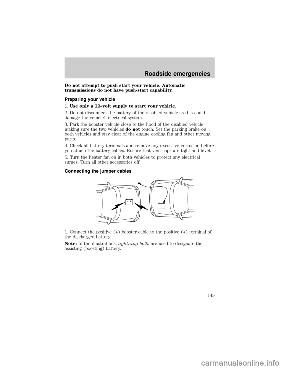
Connecting the jumper cables
1. Connect the positive (+) booster cable to the positive (+) terminal of
the discharged battery.
Note:In the illustrations,lightning boltsare used to designate the
assisting (boosting) battery.
+–+–
Roadside emergencies
145
Page 157 of 224

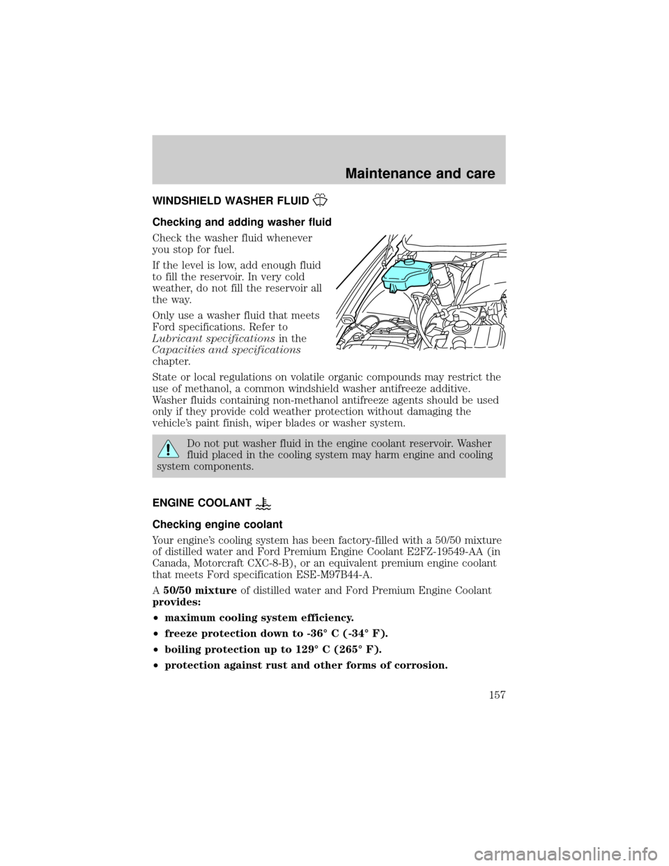
WINDSHIELD WASHER FLUID
Checking and adding washer fluid
Check the washer fluid whenever
you stop for fuel.
If the level is low, add enough fluid
to fill the reservoir. In very cold
weather, do not fill the reservoir all
the way.
Only use a washer fluid that meets
Ford specifications. Refer to
Lubricant specificationsin the
Capacities and specifications
chapter.
State or local regulations on volatile organic compounds may restrict the
use of methanol, a common windshield washer antifreeze additive.
Washer fluids containing non-methanol antifreeze agents should be used
only if they provide cold weather protection without damaging the
vehicle's paint finish, wiper blades or washer system.
Do not put washer fluid in the engine coolant reservoir. Washer
fluid placed in the cooling system may harm engine and cooling
system components.
ENGINE COOLANT
Checking engine coolant
Your engine's cooling system has been factory-filled with a 50/50 mixture
of distilled water and Ford Premium Engine Coolant E2FZ-19549-AA (in
Canada, Motorcraft CXC-8-B), or an equivalent premium engine coolant
that meets Ford specification ESE-M97B44-A.
A50/50 mixtureof distilled water and Ford Premium Engine Coolant
provides:
²maximum cooling system efficiency.
²freeze protection down to -36É C (-34É F).
²boiling protection up to 129É C (265É F).
²protection against rust and other forms of corrosion.
Maintenance and care
157