Page 121 of 224

your vehicle. It is especially useful on slippery and/or hilly road surfaces.
The system operates by detecting and controlling wheel spin. The system
borrows many of the electronic and mechanical elements already present
in the anti-lock braking system (ABS).
Wheel-speed sensors allow excess rear wheel spin to be detected by the
Traction Controlyportion of the ABS computer. Any excessive wheel
spin is controlled by automatically applying and releasing the rear brakes
in conjunction with engine torque reductions. Engine torque reduction is
realized via the fully electronic spark and fuel injection systems. This
process is very sensitive to driving conditions and very fast acting. The
rear wheels ªsearchº for optimum traction several times a second and
adjustments are made accordingly.
The Traction Controlysystem will allow your vehicle to make better use
of available traction on slippery surfaces. The system is a driver aid
which makes your vehicle easier to handle primarily on snow and ice
covered roads.
During Traction Controlyoperation you may hear an electric motor type
of sound coming from the engine compartment and the engine will not
ªrev-upº when you push further on the accelerator. This is normal
system behavior.
If you should become stuck in snow or ice or on a very slippery road
surface, try switching the Traction Controlysystem off. This may allow
excess wheel spin to ªdigº the vehicle out and enable a successful
ªrockingº maneuver.
If the Traction Controlysystem is cycled excessively, the brake portion
of the system will shut down to prevent the rear brakes from
overheating. A limited Traction Controlyfunction using only engine
torque reduction will still control wheels from over-spinning. When the
rear brakes have cooled down, the system will again function normally.
Anti-lock braking is not affected by this condition and will function
normally during the cool down period.
Traction control switch
The traction control switch is located on the left side of the glove
compartment. The traction control system defaults to ON when the
ignition key is turned from OFF to RUN.
Driving
121
Page 123 of 224

If you exceed the load limit, the rear air suspension may not operate.
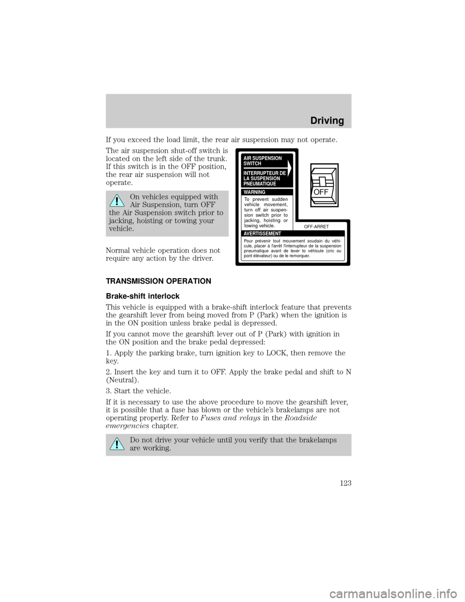
The air suspension shut-off switch is
located on the left side of the trunk.
If this switch is in the OFF position,
the rear air suspension will not
operate.
On vehicles equipped with
Air Suspension, turn OFF
the Air Suspension switch prior to
jacking, hoisting or towing your
vehicle.
Normal vehicle operation does not
require any action by the driver.
TRANSMISSION OPERATION
Brake-shift interlock
This vehicle is equipped with a brake-shift interlock feature that prevents
the gearshift lever from being moved from P (Park) when the ignition is
in the ON position unless brake pedal is depressed.
If you cannot move the gearshift lever out of P (Park) with ignition in
the ON position and the brake pedal depressed:
1. Apply the parking brake, turn ignition key to LOCK, then remove the
key.
2. Insert the key and turn it to OFF. Apply the brake pedal and shift to N
(Neutral).
3. Start the vehicle.
If it is necessary to use the above procedure to move the gearshift lever,
it is possible that a fuse has blown or the vehicle's brakelamps are not
operating properly. Refer toFuses and relaysin theRoadside
emergencieschapter.
Do not drive your vehicle until you verify that the brakelamps
are working.
AIR SUSPENSION
SWITCH
INTERRUPTEUR DE
LA SUSPENSION
PNEUMATIQUE
WARNING
AVERTISSEMENTOFF-ARRET
To prevent sudden
vehicle movement,
turn off air suspen-
sion switch prior to
jacking, hoisting or
towing vehicle.
Pour prévenir tout mouvement soudain du véhi-
cule, placer à l'arrêt l'interrupteur de la suspension
pneumatique avant de lever to véhicule (cric ou
pont élévateur) ou de le remorquer.
OFF
Driving
123
Page 124 of 224

If your vehicle gets stuck in mud or snow it may be rocked out by
shifting from forward and reverse gears, stopping between shifts, in a
steady pattern. Press lightly on the accelerator in each gear.
Do not rock the vehicle if the engine is not at normal operating
temperature or damage to the transmission may occur.
Do not rock the vehicle for more than a few minutes or damage
to the transmission and tires may occur or the engine may
overheat.
Always set the parking brake fully and make sure the gearshift is
latched in P (Park). Turn off the ignition whenever you leave
your vehicle.
If the parking brake is fully released, but the brake warning lamp
remains illuminated, the brakes may not be working properly.
See your dealer or a qualified service technician.
Driving with a 4±speed automatic transmission
Understanding gearshift positions
To put your vehicle in gear, start the engine, depress the brake pedal,
then move gearshift lever out of P (Park).
Hold the brake pedal down while you move the gearshift lever
from P (Park) to another position. If you do not hold the brake
pedal down, your vehicle may move unexpectedly and injure someone.
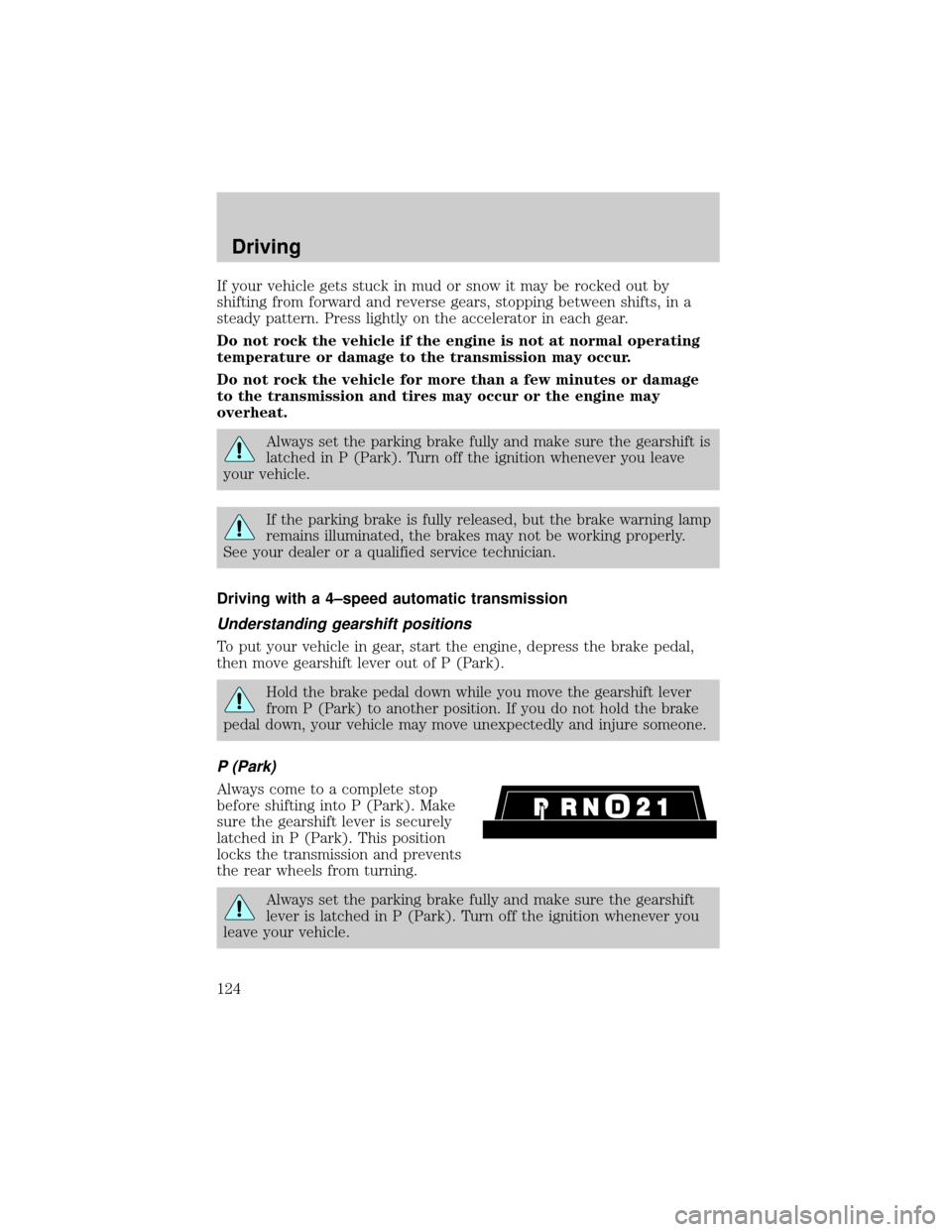
P (Park)
Always come to a complete stop
before shifting into P (Park). Make
sure the gearshift lever is securely
latched in P (Park). This position
locks the transmission and prevents
the rear wheels from turning.
Always set the parking brake fully and make sure the gearshift
lever is latched in P (Park). Turn off the ignition whenever you
leave your vehicle.
Driving
124
Page 131 of 224

Exceeding these limits may allow water to enter critical vehicle
components, adversely affecting driveability, emissions, reliability and
causing internal transmission damage.
Replace the rear axle lubricant anytime the axle has been submerged in
water. Rear axle lubricant quantities are not to be checked or changed
unless a leak is suspected or repair required.
Disconnect the wiring to the trailer before backing the trailer into the
water. Reconnect the wiring to the trailer after the trailer is removed
from the water.
DRIVING THROUGH WATER
Do not drive quickly through standing water, especially if the depth is
unknown. Traction or brake capability may be limited and if the ignition
system gets wet, your engine may stall. Water may also enter your
engine's air intake and severely damage your engine.
If driving through deep or standing water is unavoidable, proceed very
slowly. Never drive through water that is higher than the bottom of the
hubs (for trucks) or the bottom of the wheel rims (for cars).
Once through the water, always try the brakes. Wet brakes do not stop
the vehicle as effectively as dry brakes. Drying can be improved by
moving your vehicle slowly while applying light pressure on the brake
pedal.
Driving through deep water where the transmission/transmission
vent tube is submerged may allow water into the transmission
and cause internal transmission damage.
Driving
131
Page 133 of 224
Roadside coverage beyond basic warranty
In the United States, you may purchase additional roadside assistance
coverage beyond this period through the Ford Auto Club by contacting
your Ford or Lincoln Mercury dealer.
HAZARD FLASHER
Use only in an emergency to warn traffic of vehicle breakdown,
approaching danger, etc. The hazard flashers can be operated when the
ignition is off.
²The hazard lights control is
located on top of the steering
column.
²Depress hazard lights control to
activate all hazard flashers
simultaneously.
²Depress control again to turn the
flashers off.
RESETTING THE FUEL PUMP SHUT-OFF SWITCH
The fuel pump shut-off switch is a device intended to stop the electric
fuel pump when your vehicle has been involved in a substantial jolt.
After a collision, if the engine cranks but does not start, the fuel pump
shut-off switch may have been activated.
Roadside emergencies
133
Page 134 of 224
The fuel pump shut-off switch is
located on a bracket inside of the
luggage compartment.
Use the following procedure to reset the fuel pump shut-off switch.
1. Turn the ignition to the OFF position.
2. Check the fuel system for leaks.
3. If no fuel leak is apparent, reset the fuel pump shut-off switch by
pushing in on the reset button.
4. Turn the ignition to the ON position. Pause for a few seconds and
return the key to the OFF position.
5. Make a further check for leaks in the fuel system.
FUSES AND RELAYS
Fuses
If electrical components in the
vehicle are not working, a fuse may
have blown. Blown fuses are
identified by a broken wire within
the fuse. Check the appropriate
fuses before replacing any electrical
components.
15
Roadside emergencies
134
Page 137 of 224

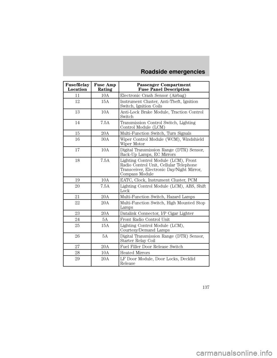
Fuse/Relay
LocationFuse Amp
RatingPassenger Compartment
Fuse Panel Description
11 10A Electronic Crash Sensor (Airbag)
12 15A Instrument Cluster, Anti-Theft, Ignition
Switch, Ignition Coils
13 10A Anti-Lock Brake Module, Traction Control
Switch
14 7.5A Transmission Control Switch, Lighting
Control Module (LCM)
15 20A Multi-Function Switch, Turn Signals
16 30A Wiper Control Module (WCM), Windshield
Wiper Motor
17 10A Digital Transmission Range (DTR) Sensor,
Back-Up Lamps, EC Mirrors
18 7.5A Lighting Control Module (LCM), Front
Radio Control Unit, Cellular Telephone
Transceiver, Electronic Day/Night Mirror,
Compass Module
19 10A EATC, Clock, Instrument Cluster, PCM
20 7.5A Lighting Control Module (LCM), ABS, Shift
Lock
21 20A Multi-Function Switch, Hazard Lamps
22 20A Multi-Function Switch, High Mounted Stop
Lamps
23 20A Datalink Connector, I/P Cigar Lighter
24 5A Front Radio Control Unit
25 15A Lighting Control Module (LCM),
Courtesy/Demand Lamps
26 5A Digital Transmission Range (DTR) Sensor,
Starter Relay Coil
27 20A Fuel Filler Door Release Switch
28 10A Heated Mirrors
29 20A LF Door Module, Door Locks, Decklid
Release
Roadside emergencies
137
Page 139 of 224
The high-current fuses are coded as follows.
Fuse/Relay
LocationFuse Amp
RatingPower Distribution Box Description
1 50A** Ignition Switch
2 40A** Ignition Switch
3 50A** Cooling Fan-High Speed
4 30A** PCM Power Relay
5 40A** I/P Fuse Panel, Fuses 10, 19, 21, 23, 25, 27
6 30A** Starting System
7 50A** I/P Fuse Panel, Fuses 1, 3, 5, 7, 9, 31
8 30A** Driver Power Seat, I/P Fuse Panel, Fuse 30
9 50A** Anti-Lock Brakes
10 40A** Rear Defrost
11 40A** Accessory Delay Relay (Signature/Cartier),
Power Window Relay (Executive), I/P Fuse
Panel, Fuse 29,
13 14
15 16
17 18
21 2219 20
23 24
25
26
27
PCM
DIODE1
2
3
4
5
6
7
8
9
10
11
12RELAY
1
RELAY
2
RELAY
3
RELAY
4
RELAY
5
Roadside emergencies
139