Page 115 of 224
2. Make sure the headlamps and vehicle accessories are off.
3. Make sure the parking brake is
set.
4. Make sure the gearshift is in P
(Park).
5. Turn the key to 4 (ON) without
turning the key to 5 (START).
If there is difficulty in turning the
key, firmly rotate the steering wheel
left and right until the key turns
freely. This condition may occur
when:
²front wheels are turned
²front wheel is against the curb
²steering wheel is turned when getting in or out of the vehicle
HOOD
1
2
34
5
10
2030405060
70
80
90
100
120206080
40100
120
160 140
180
P R N D 2 1
MPHkm/h
110
HF
E1
2
FILL ON
LEFT<
AIR
BAG CHECK
TRAC
SERVICE
ENGINE
SOON
TRUNK AJAR DOOR AJAR
TRAC OFF AIR SUSPENSION
O/D OFF TRAC ACTIVE
SPEED CONTROL COMPASSkmCIRCLE
SLOWLY FUEL ECON
DIST TO EMPTY
AVG SPEED
TRIP A B
E/M
km MILES/GALWASHER
LTR/100km
BRAKE
Starting
115
Page 118 of 224

BRAKES
Your service brakes are self-adjusting. Refer to the scheduled
maintenance guide for scheduled maintenance.
Occasional brake noise is normal and often does not indicate a
performance concern with the vehicle's brake system. In normal
operation, automotive brake systems may emit occasional or intermittent
squeal or groan noises when the brakes are applied. Such noises are
usually heard during the first few brake applications in the morning;
however, they may be heard at any time while braking and can be
aggravated by environmental conditions such as cold, heat, moisture,
road dust, salt or mud. If a ªmetal-to-metal,º ªcontinuous grindingº or
ªcontinuous squealº sound is present while braking, the brake linings
may be worn-out and should be inspected by a qualified service
technician.
Anti-lock brake system (ABS)
On vehicles equipped with an anti-lock braking system (ABS), a noise
from the hydraulic pump motor and pulsation in the pedal may be
observed during ABS braking events. Pedal pulsation coupled with noise
while braking under panic conditions or on loose gravel, bumps, wet or
snowy roads is normal and indicates proper functioning of the vehicle's
anti-lock brake system. The ABS performs a self-check after you start
the engine and begin to drive away. A brief mechanical noise may be
heard during this test. This is normal. If a malfunction is found, the ABS
warning light will come on. If the vehicle has continuous vibration or
shudder in the steering wheel while braking, the vehicle should be
inspected by a qualified service technician.
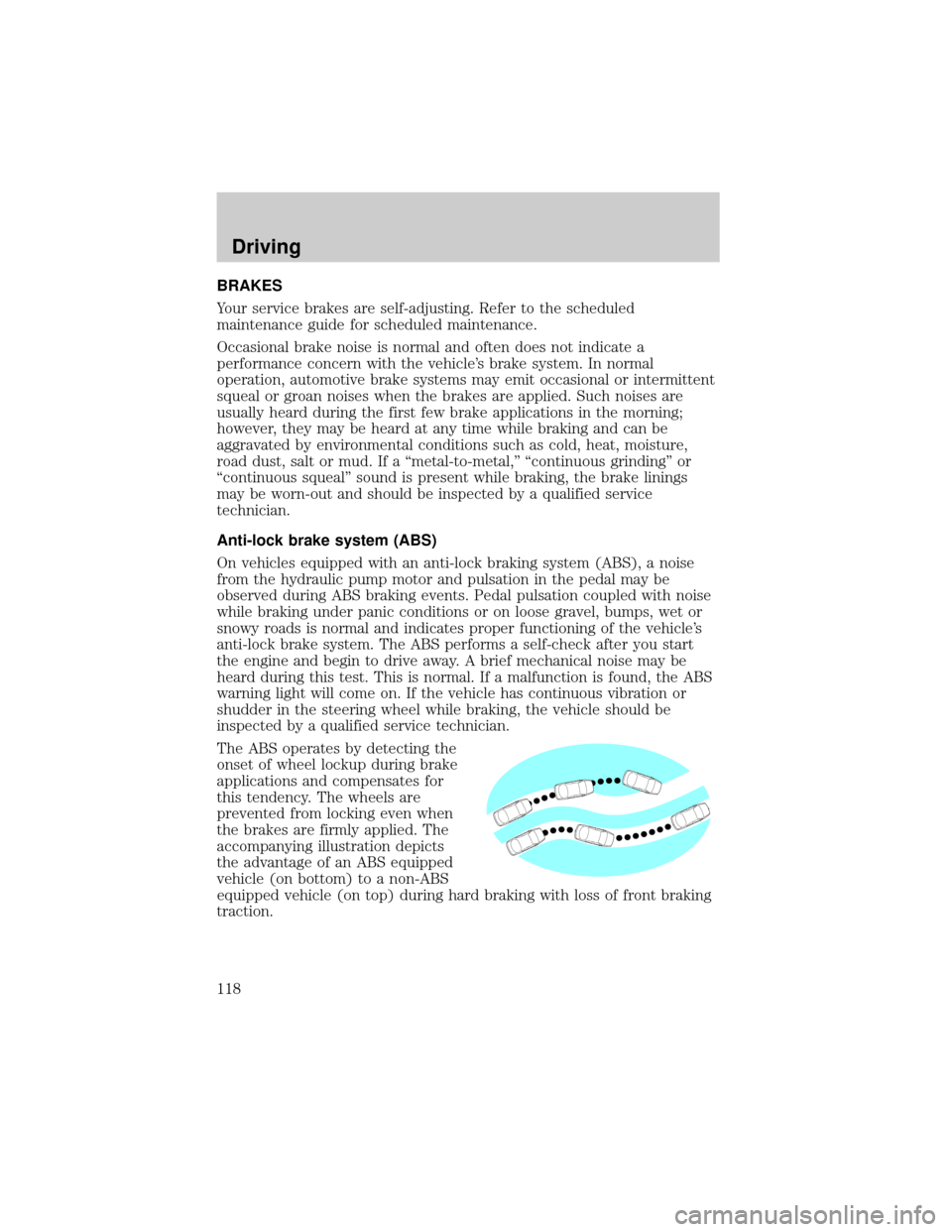
The ABS operates by detecting the
onset of wheel lockup during brake
applications and compensates for
this tendency. The wheels are
prevented from locking even when
the brakes are firmly applied. The
accompanying illustration depicts
the advantage of an ABS equipped
vehicle (on bottom) to a non-ABS
equipped vehicle (on top) during hard braking with loss of front braking
traction.
Driving
118
Page 119 of 224

ABS warning lampABS
TheABSwarning lamp in the instrument cluster momentarily illuminates
when the ignition is turned to the ON position. If the light does not
illuminate momentarily at start up, remains on or continues to flash, the
ABS needs to be serviced.
With the ABS light on, the anti-lock
brake system is disabled and normal
braking is still effective unless the
brake warning light also remains
illuminated with parking brake
released. (If your brake warning lamp illuminates, have your vehicle
serviced immediately.)
Using ABS
²In an emergency or when maximum efficiency from the ABS is
required, apply continuous force on the brake. The ABS will be
activated immediately, thus allowing you to retain full steering control
of your vehicle and, providing there is sufficient space, will enable you
to avoid obstacles and bring the vehicle to a controlled stop.
²The Anti-Lock system does not decrease the time necessary to apply
the brakes or always reduce stopping distance. Always leave enough
room between your vehicle and the vehicle in front of you to stop.
²We recommend that you familiarize yourself with this braking
technique. However, avoid taking any unnecessary risks.
Parking brake with auto-release
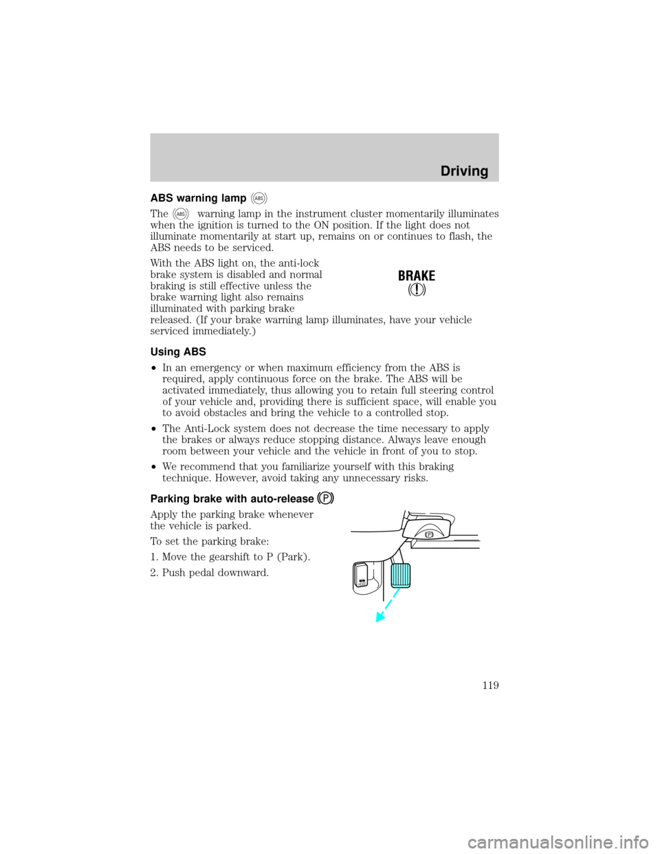
Apply the parking brake whenever
the vehicle is parked.
To set the parking brake:
1. Move the gearshift to P (Park).
2. Push pedal downward.
!
BRAKE
HOOD
Driving
119
Page 122 of 224

STEERING
Your vehicle is equipped with power steering. Power steering uses energy
from the engine to help steer the vehicle.
To prevent damage to the power steering pump:
²Never hold the steering wheel to the extreme right or the extreme left
for more than a few seconds when the engine is running.
²Do not operate the vehicle with a low power steering pump fluid level.
If the power steering system breaks down (or if the engine is turned
off), you can steer the vehicle manually, but it takes more effort.
If the steering wanders or pulls, the condition could be caused by any of
the following:
²underinflated tire(s) on any wheel(s)
²high crown in center of road
²high crosswinds
²wheels out of alignment
²loose or worn components in steering linkage
Speed sensitive steering
The steering in your vehicle is speed sensitive. At high speeds, steering
assist will decrease to improve steering feel. At lower speeds,
maneuverability will be increased.
If the amount of effort required to steer your vehicle changes at a
constant vehicle speed, have the power steering system checked by your
dealer or a qualified service technician.
AIR SUSPENSION SYSTEM
The air suspension system is designed to improve ride, handling and
general vehicle performance during:
²certain road conditions
²steering maneuvers
²braking
²accelerations
This system keeps the rear of your vehicle at a constant level by
automatically adding air or releasing air from the springs.
Driving
122
Page 133 of 224
Roadside coverage beyond basic warranty
In the United States, you may purchase additional roadside assistance
coverage beyond this period through the Ford Auto Club by contacting
your Ford or Lincoln Mercury dealer.
HAZARD FLASHER
Use only in an emergency to warn traffic of vehicle breakdown,
approaching danger, etc. The hazard flashers can be operated when the
ignition is off.
²The hazard lights control is
located on top of the steering
column.
²Depress hazard lights control to
activate all hazard flashers
simultaneously.
²Depress control again to turn the
flashers off.
RESETTING THE FUEL PUMP SHUT-OFF SWITCH
The fuel pump shut-off switch is a device intended to stop the electric
fuel pump when your vehicle has been involved in a substantial jolt.
After a collision, if the engine cranks but does not start, the fuel pump
shut-off switch may have been activated.
Roadside emergencies
133
Page 135 of 224
Always replace a fuse with one that has the specified amperage
rating. Using a fuse with a higher amperage rating can cause
severe wire damage and could start a fire.
Standard fuse amperage rating and color
COLOR
Fuse
RatingMini
FusesStandard
FusesMaxi
FusesCartridge
Maxi
FusesFuse Link
Cartridge
2A Grey Grey Ð Ð Ð
3A Violet Violet Ð Ð Ð
4A Pink Pink Ð Ð Ð
5A Tan Tan Ð Ð Ð
7.5A Brown Brown Ð Ð Ð
10A Red Red Ð Ð Ð
15A Blue Blue Ð Ð Ð
20A Yellow Yellow Yellow Blue Blue
25A Natural Natural Ð Ð Ð
30A Green Green Green Pink Pink
40A Ð Ð Orange Green Green
50A Ð Ð Red Red Red
60A Ð Ð Blue Ð Yellow
70A Ð Ð Tan Ð Brown
80A Ð Ð Natural Ð Black
Passenger compartment fuse panel
The fuse panel is located below and to the left of the steering wheel by
the brake pedal. Remove the panel cover to access the fuses.
To remove a fuse use the fuse puller tool provided on the fuse panel
cover.
Roadside emergencies
135
Page 136 of 224
The fuses are coded as follows.
Fuse/Relay
LocationFuse Amp
RatingPassenger Compartment
Fuse Panel Description
1 10A Lighting Control Module (LCM), Left-Hand
Low Beam Headlamp
2 30A EATC Blower Motor
3 10A Lighting Control Module (LCM),
Right-Hand Low Beam Headlamp
4 7.5A Instrument Cluster
5 7.5A Lighting Control Module (LCM), Park/Tail
Lamps
6 15A EATC, Heated Seats
7 15A Lighting Control Module (LCM), Day/Night
Sensor/Amplifier
8 10A Shift Lock, Speed Control, Air Suspension,
Steering Wheel Rotation Sensor
9 20A Lighting Control Module (LCM),
Multi-Function Switch, Hi Beam
Headlamps
10 20A Brake Pedal Position (BPP) Switch, Brake
Pressure Switch, Stop Lamps
27 25
26 2423 21
2219
20
18 16
17 1514 12
1310
33
31
2932
30
28 11
97
8653
41
2RELAY
1
Roadside emergencies
136
Page 140 of 224
Fuse/Relay
LocationFuse Amp
RatingPower Distribution Box Description
12 30A** Air Suspension
13 15A* Charging System
14 20A* Fuel Pump
15 Ð NOT USED
16 30A* Heated Seats
17 10A* Air Suspension
18 15A* Horn
19 30A* Subwoofer, I/P Fuse Panel, Fuse 33
20 15A* Fuel Injectors
21 15A* Heated Oxygen Sensors, Transmission
Solenoids, EVAP Canaster Vent Solenoid,
EGR Vacuum Regulator, EVAP Vapor
Management Valve
22 Ð Not Used
23 Ð Not Used
24 20A* Auxiliary Power Outlet
25 30A** Power Lumbar, Passenger Power Seat
26 30A CB Cooling Fan-Low Speed
27 Ð Not Used
Relay 1 Ð Fuel Pump Relay
Relay 2 Ð A/C Clutch Relay
Relay 3 Ð PCM Power Relay
Relay 4 Ð Air Suspension Relay
Relay 5 Ð Rear Defrost Relay
* Mini Fuses ** Maxi Fuses
CHANGING THE TIRES
If you get a flat tire while driving, do not apply the brake heavily.
Instead, gradually decrease your speed. Hold the steering wheel firmly
and slowly move to a safe place on the side of the road.
Roadside emergencies
140