Page 196 of 1111
I04026
� Engine Room No.1 Junction Block
Fuses Relays
1. MAIN H±Fuse
2. FL ABS NO.1 H±Fuse
3. ALT H±Fuse
4. ABS NO.2 H±Fuse
5. H±LP CLN H±Fuse
6. RAD NO.1 Fuse
7. ALT±S Fuse
8. EFI Fuse
9. TURN HAZ Fuse
10. TEL Fuse
11. AM2 Fuse
13. HORN Fuse 12. ETCS Fuse
14. MPX±B Fuse
15. ECU±B1 Fuse
16. HTR FuseB. Starter Relay A. Headlight Control Relay
C. EFI Relay
17. FAN MAIN H±Fuse
18. CDS FAN H±Fuse
20. H±LP R LWR Fuse 19. RAD FAN H±Fuse
21. H±LP L LWR Fuse
22. H±LP R UPR Fuse
23. H±LP L UPR Fuse1
2 3 4 5 6 7 8 9 10 11 12 13
14 15
16 18 17 19
20 21 22 23 A
BC
± BODY ELECTRICALPOWER SOURCE
BE±17
2318 Author�: Date�:
2000 LEXUS GS300/GS400 (RM718U)
Page 197 of 1111
I04028
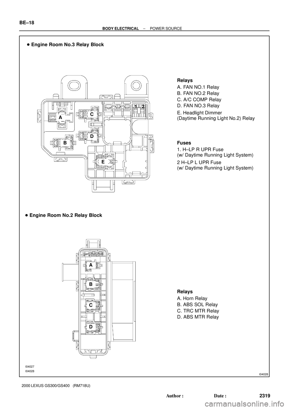
� Engine Room No.3 Relay Block
Relays
A. FAN NO.1 Relay
B. FAN NO.2 Relay
C. A/C COMP Relay
D. FAN NO.3 Relay
� Engine Room No.2 Relay Block
Relays
A. Horn Relay
B. ABS SOL Relay
C. TRC MTR Relay
D. ABS MTR Relay
I04027
I04028
A
B
C
D
EE. Headlight Dimmer
(Daytime Running Light No.2) Relay
A
B
C
DFuses
1. H±LP R UPR Fuse
(w/ Daytime Running Light System)
2 H±LP L UPR Fuse
(w/ Daytime Running Light System) 12 BE±18
± BODY ELECTRICALPOWER SOURCE
2319 Author�: Date�:
2000 LEXUS GS300/GS400 (RM718U)
Page 255 of 1111

INSPECTION
1. INSPECT ENGINE ROOM NO.1 JUNCTION BLOCK
CIRCUIT
(a) Remove the fuse from the")
BE04S±04
I05031
± BODY ELECTRICALPOWER SOURCE
BE±21
2322 Author�: Date�:
2000 LEXUS GS300/GS400 (RM718U)
INSPECTION
1. INSPECT ENGINE ROOM NO.1 JUNCTION BLOCK
CIRCUIT
(a) Remove the fuse from the junction block and inspect the
connector on junction block side.
Fuse Tester connectionConditionSpecified condition
MAIN 2 ± GroundConstantBattery positive voltage
ABS NO.1 4 ± GroundConstantBattery positive voltage
ALT 6 ± GroundConstantBattery positive voltage
ABS 8 ± GroundConstantBattery positive voltage
H±LP CLN 10 ± GroundConstantBattery positive voltage
RAD NO.1 12 ± GroundConstantBattery positive voltage
ALT±S 14 ± GroundConstantBattery positive voltage
EFI 16 ± GroundConstantBattery positive voltage
TURN HAZ 18 ± GroundConstantBattery positive voltage
TEL 20 ± GroundConstantBattery positive voltage
AM2 22 ± GroundConstantBattery positive voltage
ETCS 24 ± GroundConstantBattery positive voltage
HORN 26 ± GroundConstantBattery positive voltage
MPX±B 27 ± GroundConstantBattery positive voltage
Page 258 of 1111
I05033
BE±24
± BODY ELECTRICALPOWER SOURCE
2325 Author�: Date�:
2000 LEXUS GS300/GS400 (RM718U)
3. INSPECT ENGINE ROOM No.2 RELAY BLOCK CIR-
CUIT
Remove the relay from the relay block and inspect the connec-
tor on relay block side.
Relay Tester connectionConditionSpecified condition
HORN 1 ± GroundConstantBattery positive voltage
HORN 2 ± GroundHorn switch ONContinuity
HORN 4 ± GroundConstantBattery positive voltage
ABS SOL 5 ± GroundConstantBattery positive voltage
ABS SOL 6 ± GroundConstantContinuity
TRC MTR 11 ± GroundConstantBattery positive voltage
ABS MTR 15 ± GroundConstantBattery positive voltage
If the circuit is not as specified, inspect the circuits connected
to other parts.
Page 303 of 1111

HEADLIGHT BEAM LEVEL CONTROL SYSTEM
SymptomSuspect AreaSee page
Beam axis is not controlled. (It is not i")
BE±6
± BODY ELECTRICALTROUBLESHOOTING
2307 Author�: Date�:
2000 LEXUS GS300/GS400 (RM718U)
HEADLIGHT BEAM LEVEL CONTROL SYSTEM
SymptomSuspect AreaSee page
Beam axis is not controlled. (It is not initialized.)
Headlight Beam Level Control System does not operate.
1. ECU±IG Fuse
2. Headight Beam Level Control Actuator
3. Headlight Beam Level Control ECU
4. Wire Harness SideBE±21
BE±50
BE±50
±
Beam axis is not controlled. (It is initialized.)
Headlight Beam Level Control System does not operate.1. Height Control Sensor
2. Headlight Beam Level Control ECU
3. Wire Harness SideBE±50
BE±50
±
Controlled angle of head light is unusual.
(The angle is controlled.)
1. Height Control Sensor
2. Headlight Beam Level Control ECU
3. Headlights
4. Wire Harness Side±
BE±50
BE±3
±
Beam axis position is not stable during driving.
1. ABS System
2. Headlights
3. Wire HarnessDI±387
BE±3
±
FOG LIGHT SYSTEM
This system uses the multiplex communication system, so check diagnosis system of the multiplex commu-
nication system before you proceed with troubleshooting.
SymptomSuspect AreaSee page
Fog light does not light up with light control SW HEAD
(Headlight is normal.)
1. FOG Fuse
2. Fog Light Relay
3. Fog Light Switch
4. Wire Harness
5. Body No.2 ECUBE±21
BE±53
BE±53
±
±
Fog light does not light up with light control SW HEAD
(Headlight does not light).1.*1 Other Parts
2. Wire Harness±
±
Only one light does not light up.1. Bulb
2. Wire Harness±
±
*1: Inspect Headlight System
TURN SIGNAL AND HAZARD WARNING SYSTEM
This system uses the multiplex communication system, so check diagnosis system of the multiplex commu-
nication system before you proceed with troubleshooting.
SymptomSuspect AreaSee page
ºHazardº and ºTurnº do not light up.
1. GAUGE Fuse
2. TURN HAZ Fuse
3. Ignitioin Switch
4. Turn Signal Flasher Relay
5. Wire HarnessBE±21
BE±21
BE±31
BE±56
±
Hazard warning light does not light up.
(Turn is normal)1. Hazard Warning Switch
2. Wire HarnessBE±56
±
Turn signal does not light up.
(Hazard is normal)1. Turn Signal Switch
2. Wire HarnessBE±56
±
Turn signal does not light up in one direction.1. Turn Signal Switch
2. Wire HarnessBE±56
±
Only one bulb does not light up.1. Bulb
2. Wire Harness±
±
Page 306 of 1111
 Washer fluid does not operate.
Washer Hose and Nozzle±
� When wiper switch is in HI position, the wiper")
± BODY ELECTRICALTROUBLESHOOTING
BE±9
2310 Author�: Date�:
2000 LEXUS GS300/GS400 (RM718U) Washer fluid does not operate.
Washer Hose and Nozzle±
� When wiper switch is in HI position, the wiper blade is in contact
with the body.
� When the wiper switch is OFF, the wiper blade does not retract
or the retract position is wrong.
1. Wiper Motor *1
2. Wire harness *1BE±77
±
*1: Inspect wiper arm and blade set positions.
COMBINATION METER
�This system uses the multiplex communication system, so check diagnosis system of the multiplex
communication system before you proceed with troubleshooting.
�Refer to DI section for warning light or indicator light not described in the table below.
SymptomSuspect AreaSee page
Driver seat belt warning light does not light up.
1. Bulb
2. Driver Buckle Switch CIrcuit
3. Meter Circuit Plate
4. Wire Harness
5. Body No.2 ECU±
BE±92
BE±92
±
DI±820
Passenger seat belt warning light does not light up.
1. Clock System
2. Passenger Buckle Switch CIrcuit
3. Occupant Detection Sensor
4. Meter Circuit Plate
5. Wire Harness
6. Body No.1 ECUBE±227
BE±92
BE±92
BE±92
±
DI±776
SRS warning light does not light up.
1. MPX±B Fuse
2. SRS±B Fuse
3. Bulb
4. Meter Circuit Plate
5. Wire Harness
6. Airbag Sensor AssemblyBE±21
BE±21
±
BE±92
±
DI±550
Hi±beam indicator light does not light up.
1. Bulb
2. Meter Circuit Plate
3. Wire Harness
4. Headlight System±
BE±92
±
BE±3
Turn indicator light does not light up.
1. Bulb
2. Meter Circuit Plate
3. Wire Harness
4. Turn Signal and Hazard Warning System±
BE±92
±
BE±3
ABS warning light does not light up.
1. GAUGE Fuse
2. Bulb
3. Meter Circuit Plate
4. Wire Harness
5. ABS, TRAC and VSC ECUBE±21
±
BE±92
±
DI±387
TRAC warning light does not light up.
1. GAUGE Fuse
2. Bulb
3. Meter Circuit Plate
4. Wire Harness
5. ABS, TRAC and VSC ECUBE±21
±
BE±92
±
DI±473
Page 363 of 1111
BE0HH±07
I01359
Brake Master Cylinder
� Brake Fluid Level
Warning Switch
Combination Meter
and Telltale Light
Assembly
Airbag Sensor Assembly Parking Brake Switch
Driver Side
Junction Block
� GAUGE Fuse
� SRS±B FuseIgnition Switch
ECM
Washer Tank
� Washer Level
Warning Switch Engine Room No.1
Junction Block
� MPX±B Fuse
Seat Belt Buckle Switch
Rheostat Light Control
ABS, TRAC and VSC ECU
Clock Assembly
� Passenger Seat Belt
Waning Light
BE±80
± BODY ELECTRICALCOMBINATION METER
2381 Author�: Date�:
2000 LEXUS GS300/GS400 (RM718U)
COMBINATION METER
LOCATION
�The vehicle shown in this illustration is ºGS400º.
�All components of ºGS300º other than the ones used for engine are same as ºGS400º.
Page 366 of 1111
I04250
� Combination Meter Wiring Circuit ± 1
:Speedometer
:Tachometer
:Fuel Receiver Gauge
:Engine Coolant
Temperature
Receiver Gauge
Speed Control Unit
CLOCK
to GAUGE Fuse
to MPX±B Fuse
to SRS Fuse
Tilt and Telescopic ECU
Body ECU NO.2ECM (GS400)
Ignitor (GS300)
Fuel Main Sender GaugeGround
Fuel Sub Sender Gauge
Light Control Rheostat
Illuminations
ABS, TRAC and VSC ECU
ABS, TRAC and VSC ECU Speed Signal Passenger seat
belt warning
Rr LIGHTS
SEAT BELT
OIL PRESS
OIL LEVEL
DOOR IG+
SRS +BA/T P
A/T R
A/T N
A/T D
A/T 4
A/T 3
A/T 2
A/T L
CRUISE MPX+BIG+IG+
5V
+B
to ECUto
PANEL
Fuse B4
B5
B6
B9
A5
A17A3A8 B16
LCDECU S
T
F
E
Power Source
Brake
Buzzer A11A2 A1 A6
B1
B13
B14A4
B22 ECU
ECU
ECU
S
T
F
E
CHARGE
FUEL LVL
ECT PWR
ECT SNOW TAIL or HEAD
Ground IG+IG+ IG+ IG+
+B
± BODY ELECTRICALCOMBINATION METER
BE±83
2384 Author�: Date�:
2000 LEXUS GS300/GS400 (RM718U)