Page 938 of 1111

INSTALLATION
1. INSTALL GROMMET AND BRACKET
2. INSTALL PS GEAR ASSEMBLY
(a) Torque the 4 g")
SR0E7±01
F02565
± STEERINGPOWER STEERING GEAR
SR±57
2227 Author�: Date�:
2000 LEXUS GS300/GS400 (RM718U)
INSTALLATION
1. INSTALL GROMMET AND BRACKET
2. INSTALL PS GEAR ASSEMBLY
(a) Torque the 4 gear assembly set bolts.
Torque: 65 N´m (660 kgf´cm, 48 ft´lbf)
(b) Connect the connector.
3. 2JZ±GE Engine:
CONNECT TUBE CLAMP
Torque the bolt.
Torque: 5 N´m (55 kgf´cm, 48 in.´lbf)
4. 1UZ±FE Engine:
CONNECT 2 TUBE CLAMPS
Torque the bolt.
Torque: 5 N´m (55 kgf´cm, 48 in.´lbf)
5. CONNECT INTERMEDIATE SHAFT ASSEMBLY
(See page SR±17)
6. CONNECT PRESSURE FEED AND RETURN TUBES
(a) Pressure feed tube:
Torque the union bolt over a new gaskets.
Torque: 42 N´m (430 kgf´cm, 31 ft´lbf)
(b) Return tube:
Torque the union bolt with a new gasket on each side of
the tube.
Torque: 42 N´m (430 kgf´cm, 31 ft´lbf)
7. CONNECT RH AND LH TIE ROD ENDS
(See page SA±9)
8. POSITION FRONT WHEELS FACING STRAIGHT
AHEAD
HINT:
Do it with the front of the vehicle jacked up.
9. CENTER SPIRAL CABLE
(See page SR±17)
10. INSTALL STEERING WHEEL
(a) Align the matchmarks on the wheel and steering column
main shaft.
(b) Temporarily tighten the wheel set nut.
(c) Connect the connector.
11. BLEED POWER STEERING SYSTEM
(See page SR±3)
12. CHECK STEERING WHEEL CENTER POINT
13. TORQUE STEERING WHEEL SET NUT
Torque: 35 N´m (360 kgf´cm, 26 ft´lbf)
14. INSTALL STEERING WHEEL PAD
(See page SR±17)
15. CHECK FRONT WHEEL ALIGNMENT
(See page SA±4)
Page 939 of 1111
SR0E8±01
F03696
1UZ±FE:
PPS Solenoid Valve
2JZ±GE:
PPS Solenoid
ValveTilt and Telescopic ECU
PPS ECU
SR±58
± STEERINGPROGRESSIVE POWER STEERING (PPS)
2228 Author�: Date�:
2000 LEXUS GS300/GS400 (RM718U)
PROGRESSIVE POWER STEERING (PPS)
LOCATION
Page 941 of 1111

STEERING WHEEL
INSP")
F02558
SR0DJ±01
F02559
F03673
PPS Solenoid
Connector
2JZ±GE:
1UZ±FE:PPS Solenoid
Connector
SR±8
± STEERINGSTEERING WHEEL
2178 Author�: Date�:
2000 LEXUS GS300/GS400 (RM718U)
STEERING WHEEL
INSPECTION
1. CHECK STEERING WHEEL FREEPLAY
With the vehicle stopped and tires pointed straight ahead, rock
the steering wheel gently back and forth with light finger pres-
sure.
Freeplay should not exceed the maximum.
Maximum freeplay: 30 mm (1.18 in.)
2. CHECK STEERING EFFORT
(a) Center the steering wheel.
(b) Remove the steering wheel pad. (See page SR±11)
(c) Start the engine and run it at idle.
(d) Measure the steering effort in both directions.
Reference: 7 N´m (70 kgf´cm, 61 in.´lbf)
HINT:
Be sure to consider the tire type, pressure and contact surface
before making your diagnosis.
(e) Disconnect the PPS solenoid connector.
(f) Measure the steering effort in both directions and check
that the steering effort exceeds the reference value in (d),
and that the power assist is operating. If steering effort is
not heavier than (d), check the solenoid.
HINT:
Take the tire type, pressure and contact surface into consider-
ation before making your diagnosis.
(g) Connect the connector.
(h) Torque the steering wheel set nut.
Torque: 35 N´m (360 kgf´cm, 26 ft´lbf)
(i) Install the steering wheel pad.
(See page SR±17)
Page 942 of 1111
SR0DK±03
F03671
Column Upper CoverCombination Switch
(w/ Spiral Cable)Steering Wheel Lower
No.2 CoverTorx Screw
Steering Wheel Pad
Steering Wheel
Steering Wheel Lower No.3
Cover
Finish Plate Steering Column
Assembly
Column Lower Cover
8.8 (90, 78 in.´lbf)
Torx Screw
8.8 (90, 78 in.´lbf)
35 (360, 26)
25 (260, 19)
End Pad
No.1 Safety
Pad Brake Pedal
Return Spring
Dust Cover
Intermediate Shaft
Assembly
Heater to Register Dust No.7
OBD II
No.1 Under CoverHood Lock Release
Lever
N´m (kgf´cm, ft´lbf) : Specified torque
35 (360, 26)
± STEERINGPOWER TILT AND POWER TELESCOPIC STEERING
COLUMNSR±9
2179 Author�: Date�:
2000 LEXUS GS300/GS400 (RM718U)
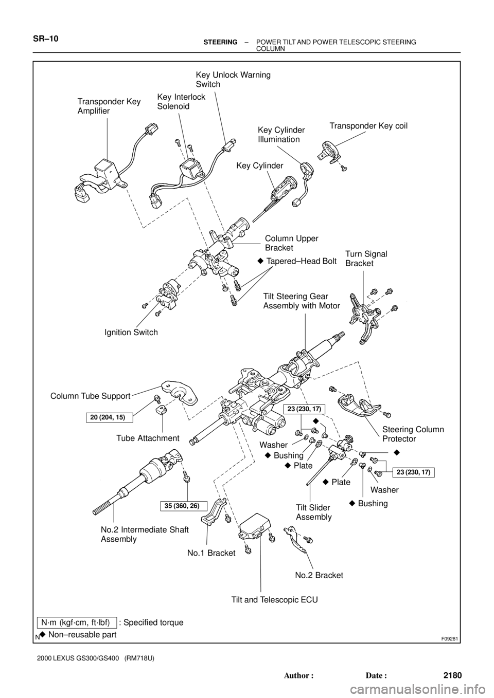
POWER TILT AND POWER TELESCOPIC STEERING
COLUMN
COMPONENTS
Page 943 of 1111
F09281
No.2 Intermediate Shaft
Assembly
Tilt and Telescopic ECUNo.2 BracketSteering Column
Protector
No.1 Bracket Column Tube SupportIgnition Switch� Tapered±Head Bolt
Tilt Steering Gear
Assembly with MotorTurn Signal
Bracket Key Interlock
SolenoidKey Unlock Warning
Switch
Key Cylinder
Illumination
Key Cylinder
35 (360, 26)
N´m (kgf´cm, ft´lbf) : Specified torque
� Non±reusable part
20 (204, 15)
Tube Attachment
Column Upper
BracketTransponder Key coil
Transponder Key
Amplifier
� Plate
Tilt Slider
Assembly23 (230, 17)
�
� Bushing�
23 (230, 17)
� Plate
� Bushing
Washer
Washer
SR±10± STEERINGPOWER TILT AND POWER TELESCOPIC STEERING
COLUMN
2180 Author�: Date�:
2000 LEXUS GS300/GS400 (RM718U)
Page 944 of 1111

SRS AIRBAG
PRECAUTION
NOTICE:
�The LEXUS GS 400/300 is equipped with SRS, which compri")
RS01Y±06
± SUPPLEMENTAL RESTRAINT SYSTEMSRS AIRBAG
RS±1
2232 Author�: Date�:
2000 LEXUS GS300/GS400 (RM718U)
SRS AIRBAG
PRECAUTION
NOTICE:
�The LEXUS GS 400/300 is equipped with SRS, which comprises a driver airbag, front passenger
airbag and side airbag. Failure to carry out service operations in the correct sequence could
cause the SRS to unexpectedly deploy during servicing, possibly leading to a serious accident.
Further, if a mistake is made in servicing the SRS, it is possible that the SRS may fail to operate
when required. Before performing servicing (including removal or installation of parts, inspec-
tion or replacement), be sure to read the following items carefully, then follow the correct proce-
dures described in the repair manual.
�Malfunction symptoms of the SRS are difficult to confirm, so the DTCs become the most impor-
tant source of information when troubleshooting. When troubleshooting the SRS, always in-
spect the DTCs before disconnecting the battery.
�Even in cases of a minor collision where the SRS does not deploy, the steering wheel pad, front
passenger airbag assembly, side airbag assembly, airbag sensor assembly, front airbag sen-
sor and side airbag sensor assembly should be inspected (See page RS±15, RS±29, RS±42
, RS±60 and RS±65).
�Never use SRS parts from another vehicle. When replacing parts, replace them with new parts.
�Never disassemble and repair the steering wheel pad, front passenger airbag assembly, side
airbag assembly, airbag sensor assembly, front airbag sensor or side airbag sensor assembly
in order to reuse it.
�If the steering wheel pad, front passenger airbag assembly, side airbag assembly, airbag sen-
sor assembly, front airbag sensor or side airbag sensor assembly has been dropped, or if there
are cracks, dents or other defects in the case, bracket or connector, replace them with new
ones.
�Use a volt/ohmmeter with high impedance (10 kW/V minimum) for troubleshooting the system's
electrical circuits.
�Information labels are attached to the periphery of the SRS components. Follow the instruc-
tions on the notices.
�After work on the SRS is completed, perform the SRS warning light check or SRS side airbag
warning light check (See page DI±552).
�If the vehicle is equipped with a mobile communication system, refer to the precaution in the
IN section.
CAUTION:
�Work must be started after 90 seconds from when the ignition switch is turned to the ºLOCKº
position and the negative (±) terminal cable is disconnected from the battery.
(The SRS is equipped with a back±up power source so that if work is started within 90 seconds
from disconnecting the negative (±) terminal cable of the battery, the SRS may be deployed.)
�When the negative (±) terminal cable is disconnected from the battery, the memory of the clock
and audio system will be canceled. So before starting work, make a record of the contents mem-
orized in the audio memory system. When work is finished, reset the audio systems as they
were before and adjust the clock. To avoid erasing the memory in each memory system, never
use a back± up power supply from outside the vehicle.
�Before repairs, remove the airbag sensor if shocks are likely to be applied to the sensor during
repairs.
�Do not expose the steering wheel pad, front passenger airbag assembly, side airbag assembly,
airbag sensor assembly, front airbag sensor or side airbag sensor assembly directly to hot air
or flames.
Page 950 of 1111

1. AI")
AB0158
SSTBattery
AB0152
SST
AB0158
SSTBattery
H01580
SST
H03723
RS±18
± SUPPLEMENTAL RESTRAINT SYSTEMSTEERING WHEEL PAD AND SPIRAL CABLE
2249 Author�: Date�:
2000 LEXUS GS300/GS400 (RM718U)
1. AIRBAG DEPLOYMENT WHEN SCRAPPING VE-
HICLE
HINT:
Have a battery ready as the power source to deploy the airbag.
(a) Check functioning of SST
CAUTION:
When deploying the airbag, always use the specified SST:
SRS Airbag Deployment Tool.
SST 09082±00700
(1) Connect the SST battery.
Connect the red clip of the SST to the battery posi-
tive (+) terminal and the black clip to the battery neg-
ative (±) terminal.
HINT:
Do not connect the yellow connector which will be connected
with the supplemental restraint system.
(2) Check functioning of SST.
Press the SST activation switch, and check that the
LED of the SST activation switch lights up.
CAUTION:
If the LED lights up when the activation switch is not being
pressed, SST malfunction is probable, so definitely do not
use the SST.
(b) Install the SST.
CAUTION:
Check that there is no looseness in the steering wheel and
steering wheel pad.
(1) Remove the steering column lower cover.
Remove the 3 screws and steering column lower
cover as shown in the illustration.
(2) Disconnect the airbag connector of the spiral cable.
Page 952 of 1111

2. DEPLOYMENT WHEN DISPOSING OF STEERING
WHEEL PAD O")
H03720
H03722
L
M RS±20
± SUPPLEMENTAL RESTRAINT SYSTEMSTEERING WHEEL PAD AND SPIRAL CABLE
2251 Author�: Date�:
2000 LEXUS GS300/GS400 (RM718U)
2. DEPLOYMENT WHEN DISPOSING OF STEERING
WHEEL PAD ONLY
NOTICE:
�When disposing of the steering wheel pad (with air-
bag) only, never use the customer's vehicle to deploy
the airbag.
�Be sure to follow the procedure given below when de-
ploying the airbag.
HINT:
Have a battery ready as the power source to deploy the airbag.
(a) Remove the steering wheel pad (See page SR±11).
CAUTION:
When storing the steering wheel pad, keep the upper sur-
face of the pad facing upward.
(b) Remove the steering wheel pad connector.
Remove the connector on the rear surface of the steering
wheel pad from the bracket.
(c) Fix steering wheel pad to disc wheel with tire.
(1) Install the 2 bolt with washers in the 2 bolt holes on
the steering wheel pad.
Bolt:
L: 35. mm (1.387 in.)
M: 6.0 mm (0.236 in.)
Pitch: 1.0 mm (0.039 in.)
NOTICE:
�Tighten the bolts by hand until the bolts become diffi-
cult to turn.
�Do not tighten the bolts too much.

Steering Wheel Lower
No.2 CoverTorx Screw
Steering Wheel Pad
Steering Wheel
Steering Wheel Lower No.3
Cover
Finish Plate Steering")