Page 1044 of 1111
SA±32
± SUSPENSION AND AXLEFRONT LOWER SUSPENSION ARM
2032 Author�: Date�:
2000 LEXUS GS300/GS400 (RM718U)
13. REMOVE NO.1 AND NO.2 LOWER SUSPENSION
ARMS
(a) Remove the bolt, shock absorber bracket from the No.1
lower suspension arm.
Torque: 59 N´m (600 kgf´cm, 44 ft´lbf)
(b) Remove the 2 bolts and separate the No.1 and No.2 lower
suspension arms.
Page 1045 of 1111
SA0RO±01
± SUSPENSION AND AXLEFRONT LOWER SUSPENSION ARM
SA±33
2033 Author�: Date�:
2000 LEXUS GS300/GS400 (RM718U)
INSTALLATION
Installation is in the reverse order of removal (See page SA±30).
AFTER INSTALLATION, CHECK ABS SPEED SENSOR SIGNAL (See page DI±389) AND FRONT
WHEEL ALIGNMENT (See page SA±4)
Page 1058 of 1111
SA0RY±01
F03420
Washer
Suspension Member BraceBrake Caliper
Axle Carrier Assembly
Parking Brake
Cable
Parking Brake
Backing Plate Dust Deflector
Axle CarrierHub Bolt
Axle Hub
Snap Ring Disc
Lock Cap
289 (2,950, 213)
59 (600, 44)
75 (765, 55)
108 (1,100, 80)
104 (1,065, 77)Drive Shaft X6
� Cotter Pin
� Bearing
N´m (kgf´cm, ft´lbf): Specified torque
� Non±reusable part
50 (510, 37)
83 (850, 61)
110 (1,120, 81)
7.8 (80, 69 in.´lbf)
7.8 (80, 69 in.´lbf)
59 (600, 43)
ABS Speed Sensor
± SUSPENSION AND AXLEREAR AXLE CARRIER
SA±43
2043 Author�: Date�:
2000 LEXUS GS300/GS400 (RM718U)
REAR AXLE CARRIER
COMPONENTS
Page 1059 of 1111

REMOVAL
1. REMOVE REAR WHEEL
Torque: 103 N´m (1,050 kgf´cm, 76 ft´lbf)")
SA0RZ±01
F02396
F02326
SA±44
± SUSPENSION AND AXLEREAR AXLE CARRIER
2044 Author�: Date�:
2000 LEXUS GS300/GS400 (RM718U)
REMOVAL
1. REMOVE REAR WHEEL
Torque: 103 N´m (1,050 kgf´cm, 76 ft´lbf)
2. REMOVE ABS SPEED SENSOR
Torque: 7.8 N´m (80 kgf´cm, 69 in.´lbf)
3. REMOVE REAR BRAKE CALIPER AND DISC
(a) Remove the 2 bolts and brake caliper from the axle hub.
(b) Support the brake caliper securely.
(c) Remove the disc.
4. CHECK BEARING BACKLASH AND AXLE HUB DEVI-
ATION
(a) Using a dial indicator near the center of the axle hub and
check the backlash in the bearing shaft direction.
Maximum: 0.05 mm (0.0020 in.)
If the backlash exceeds the specified maximum, replace the
bearing.
(b) Using a dial indicator, check the deviation at the surface
of the axle hub outside the hub bolt.
Maximum: 0.07 mm (0.0028 in.)
If the deviation exceeds the specified maximum, replace the
axle hub.
5. INSTALL DISC AND BRAKE CALIPER
(a) Install the disc.
(b) Install the brake caliper and 2 bolts to the axle carrier.
Torque: 104 N´m (1,065 kgf´cm, 77 ft´lbf)
6. REMOVE DRIVE SHAFT (See page SA±52)
7. REMOVE BRAKE CALIPER AND DISC (See step 2)
8. REMOVE PARKING BRAKE SHOE
(See page BR±33)
9. DISCONNECT PARKING BRAKE CABLE
Remove the 2 bolts and disconnect the parking brake cable.
Torque: 7.8 N´m (80 kgf´cm, 69 in.´lbf)
10. DISCONNECT UPPER SUSPENSION ARM FROM
AXLE CARRIER
(a) Remove the nut.
Torque: 108 N´m (1,100 kgf´cm, 80 ft´lbf)
Page 1068 of 1111
R08193
R12345
± SUSPENSION AND AXLEREAR DRIVE SHAFT
SA±55
2055 Author�: Date�:
2000 LEXUS GS300/GS400 (RM718U)
(d) Mount the inboard joint in a soft jaw vise.
(e) Using a screwdriver and hammer, tap out the inboard joint
cover from the inboard joint.
NOTICE:
Make sure the cage and inner race are not positioned too
much to one side of the outer race.
5. REMOVE BOOTS
Remove the inboard and outboard joint boots.
6. REMOVE NO.2 DUST DEFLECTOR
(a) Mount the outboard joint in a soft jaw vise.
(b) Using a screwdriver, remove the No.2 dust deflector.
NOTICE:
Be careful not to damage the ABS speed sensor rotor.
Page 1069 of 1111

REASSEMBLY
1. INSTALL NEW")
SA0S7±01
R12766
SST
SA0721
Matchmarks
SA1328
Narrow
Wide
SA0830
R 11111
SA±56
± SUSPENSION AND AXLEREAR DRIVE SHAFT
2056 Author�: Date�:
2000 LEXUS GS300/GS400 (RM718U)
REASSEMBLY
1. INSTALL NEW NO.2 DUST DEFLECTOR
Using SST and a press, install a new No.2 dust deflector.
SST 09309±36010, 09502±12010
NOTICE:
Be careful not to damage the ABS speed sensor rotor.
2. ASSEMBLE INBOARD JOINT
If the joint has come apart, reassemble it in the following order.
(a) Align the matchmarks placed before removal.
HINT:
When the matchmarks have disappeared, do the following pro-
cedure.
(1) Install the inner race to the cage so that the in-
dented bevelled part of the inner race is on the op-
posite side to the bevelled top of the cage.
(2) Install the outer race so that the indented side of the
outer race is facing the same side as the bevelled
surface of the cage.
(3) Match the narrow projections of the inner race with
the wide projections of the outer race.
(b) Tilt the cage and inner race to the side and insert the balls
one by one.
NOTICE:
When the cage and inner race are tilted over, support the
joint with your hand to prevent the balls from falling out.
3. TEMPORARILY INSTALL NEW BOOTS AND NEW
BOOT CLAMPS
(a) Place 4 new boot clamps to each boots.
HINT:
Before installing the boots, wrap vinyl tape around the spline of
the shaft to prevent damaging the boots.
(b) Install the 2 boots to the drive shaft.
Page 1072 of 1111
SA0S8±01
± SUSPENSION AND AXLEREAR DRIVE SHAFT
SA±59
2059 Author�: Date�:
2000 LEXUS GS300/GS400 (RM718U)
INSTALLATION
Installation is in the reverse order of removal (See page SA±52).
AFTER INSTALLATION, CHECK ABS SPEED SENSOR SIGNAL (See page DI±389)
Page 1101 of 1111
SA0SI±01
F01983
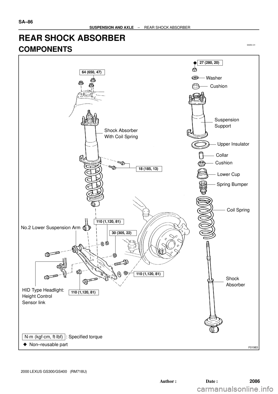
64 (650, 47)
27 (280, 20)
18 (185, 13)
�
Shock Absorber
With Coil SpringWasher
Cushion
Suspension
Support
Upper Insulator
Collar
Cushion
Spring Bumper
Coil Spring
110 (1,120, 81)
110 (1,120, 81)HID Type Headlight:
Height Control
Sensor linkShock
Absorber No.2 Lower Suspension Arm
N´m (kgf´cm, ft´lbf) : Specified torque
Non±reusable part �
110 (1,120, 81)
30 (305, 22)
Lower Cup
SA±86
± SUSPENSION AND AXLEREAR SHOCK ABSORBER
2086 Author�: Date�:
2000 LEXUS GS300/GS400 (RM718U)
REAR SHOCK ABSORBER
COMPONENTS