Page 888 of 1111
STARTER
ST±15
1633 Au")
ST054±01
B01964
Terminal 50
Battery
Terminal C
B01965
Battery
Terminal CDisconnect
B01966
Disconnect
Battery
B01967
Battery Terminal 30
Terminal 50
Ammeter
± STARTING (2JZ±GE)STARTER
ST±15
1633 Author�: Date�:
2000 LEXUS GS300/GS400 (RM718U)
TEST
NOTICE:
These tests must be done within 3 to 5 seconds to avoid
burning out the coil.
1. DO PULL±IN TEST
(a) Disconnect the field coil lead wire from terminal C.
(b) Connect the battery to the magnetic switch as shown.
Check that the pinion gear moves outward.
2. DO HOLD±IN TEST
While connected as above with the pinion gear out, disconnect
the negative (±) lead from terminal C.
Check that the pinion gear remains out.
3. INSPECT CLUTCH PINION GEAR RETURN
Disconnect the negative (±) lead from the starter body.
Check that the pinion gear returns inward.
4. DO NO±LOAD PERFORMANCE TEST
(a) Connect the battery and ammeter to the starter as shown.
(b) Check that the starter rotates smoothly and steadily with
the pinion gear moving out. Check that the ammeter
shows the specified current.
Specified current: 90 A or less at 11.5 V
Page 892 of 1111
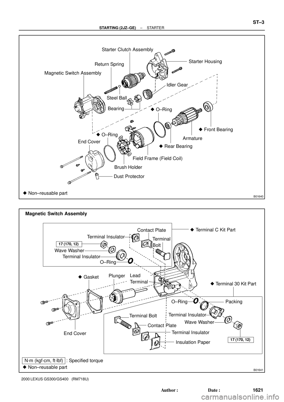
B01640
Starter Clutch Assembly
Magnetic Switch AssemblyReturn SpringStarter Housing
Idler Gear
Steel Ball
� O±Ring
Armature� Front Bearing
� Rear Bearing
Field Frame (Field Coil)
Dust Protector
� Non±reusable part
Brush Holder
� O±Ring
End CoverBearing
B01641
� Terminal C Kit Part
� Terminal 30 Kit Part
� Non±reusable partTerminal Insulator
Wave Washer
Terminal Insulator
O±RingContact Plate
Terminal
Bolt
17 (170, 12)
End Cover� GasketPlunger
Lead
Terminal
O±RingPacking
Terminal Insulator
Wave Washer
17 (170, 12)
Terminal Bolt
Contact Plate
Terminal Insulator
Insulation Paper
N´m (kgf´cm, ft´lbf) : Specified torqueMagnetic Switch Assembly
± STARTING (2JZ±GE)STARTER
ST±3
1621 Author�: Date�:
2000 LEXUS GS300/GS400 (RM718U)
Page 894 of 1111

(2)(3)(4)
(5)
ST0948
Magnetic Finger
± STARTING (2JZ±GE)STARTER
ST±5
1623 Author�: Date�:
2000 LEXUS GS300/GS400 (RM718U)
DISASSEMBLY
DISASSEMBLY
1. REMO")
ST050±01
B02814
B01647
B01959
B01970
(1)
(2)(3)(4)
(5)
ST0948
Magnetic Finger
± STARTING (2JZ±GE)STARTER
ST±5
1623 Author�: Date�:
2000 LEXUS GS300/GS400 (RM718U)
DISASSEMBLY
DISASSEMBLY
1. REMOVE DUST PROTECTOR
2. REMOVE FIELD FRAME AND ARMATURE
(a) Remove the nut, and disconnect the lead wire from the
magnetic switch terminal.
Torque: 5.9 N´m (60 kgf´cm, 52 in.´lbf)
(b) Remove the 2 through bolts.
Torque: 5.9 N´m (60 kgf´cm, 52 in.´lbf)
(c) Pull out the field frame together with the armature.
HINT:
Align the protrusion of the field frame with the groove of the
magnetic switch.
(d) Remove the O±ring from the field frame.
HINT:
At the time of installation, please refer to the following items.
Use a new O±ring.
3. REMOVE STARTER HOUSING, CLUTCH ASSEMBLY
AND GEAR
(a) Remove the 2 bolts.
Torque: 5.9 N´m (60 kgf´cm, 52 in.´lbf)
(b) Remove these parts from the magnetic switch:
(1) Starter housing
(2) Return spring
(3) Idler gear
(4) Bearing
(5) Clutch assembly
4. REMOVE STEEL BALL
Using a magnetic finger, remove the steel ball from the clutch
shaft hole.
Page 898 of 1111
STARTER
ST±9
1627 Author�: Date�:
2000 LEXU")
P10592
Ohmmeter
No Continuity
P10821
Free
LOCK
B01968
Ohmmeter
Continuity
Terminal CTerminal 50
B01969
Ohmmeter
Continuity
Terminal 50
± STARTING (2JZ±GE)STARTER
ST±9
1627 Author�: Date�:
2000 LEXUS GS300/GS400 (RM718U)
6. INSPECT BRUSH HOLDER
Check the brush holder insulator. Using an ohmmeter, check
that there is no continuity between the positive (+) and negative
(±) brush holders.
If there is continuity, repair or replace the brush holder.
7. INSPECT CLUTCH AND GEAR
(a) Check the gear teeth on the pinion gear, idle gear and the
clutch assembly for wear or damage.
If damaged, replace the gear or clutch assembly.
If damaged, also check the drive plate ring gear for wear or
damage.
(b) Check the clutch pinion gear.
Rotate the pinion gear counterclockwise, and check that
it turns freely. Try to rotate the pinion gear clockwise and
check that it locks.
If necessary, replace the clutch assembly.
8. INSPECT MAGNETIC SWITCH
(a) Check the pull ±in coil for open circuit.
Using an ohmmeter, check that there is continuity be-
tween terminals 50 and C.
If there is no continuity, check and replace the magnetic switch.
(b) Check the hold±in coil for open circuit.
Using an ohmmeter, check that there is continuity be-
tween terminal 50 and the switch body.
If there is no continuity, replace the magnetic switch.
9. INSPECT BEARING
Turn the bearing by hand and while apply inward force.
If resistance is felt or bearing sticks, replace the bearing.
(See page ST±10)