Page 640 of 1111
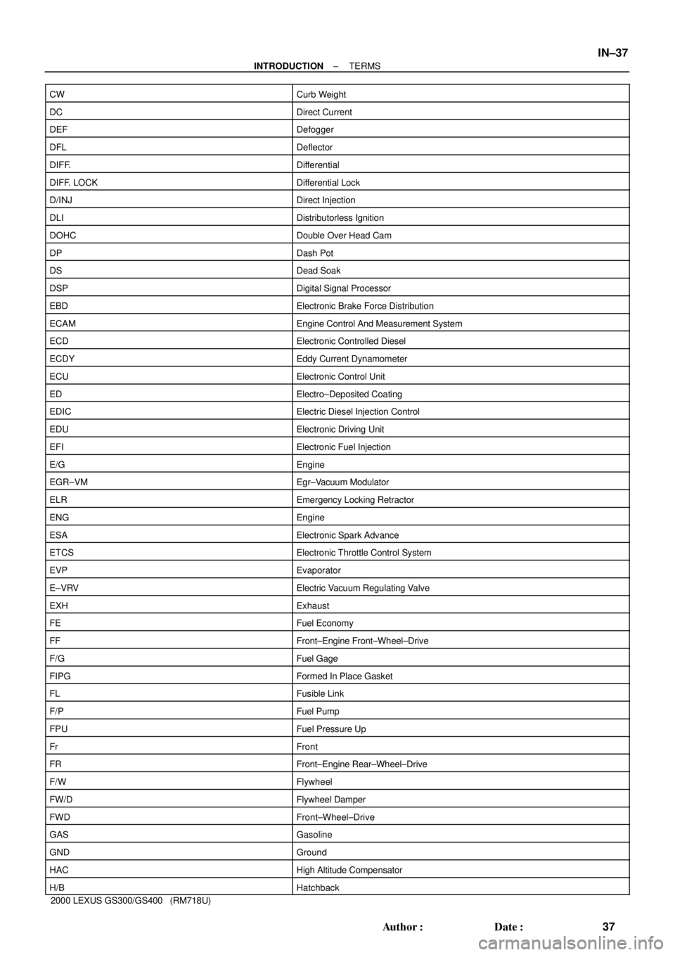
± INTRODUCTIONTERMS
IN±37
37 Author�: Date�:
2000 LEXUS GS300/GS400 (RM718U) CW
Curb Weight
DCDirect Current
DEFDefogger
DFLDeflector
DIFF.Differential
DIFF. LOCKDifferential Lock
D/INJDirect Injection
DLIDistributorless Ignition
DOHCDouble Over Head Cam
DPDash Pot
DSDead Soak
DSPDigital Signal Processor
EBDElectronic Brake Force Distribution
ECAMEngine Control And Measurement System
ECDElectronic Controlled Diesel
ECDYEddy Current Dynamometer
ECUElectronic Control Unit
EDElectro±Deposited Coating
EDICElectric Diesel Injection Control
EDUElectronic Driving Unit
EFIElectronic Fuel Injection
E/GEngine
EGR±VMEgr±Vacuum Modulator
ELREmergency Locking Retractor
ENGEngine
ESAElectronic Spark Advance
ETCSElectronic Throttle Control System
EVPEvaporator
E±VRVElectric Vacuum Regulating Valve
EXHExhaust
FEFuel Economy
FFFront±Engine Front±Wheel±Drive
F/GFuel Gage
FIPGFormed In Place Gasket
FLFusible Link
F/PFuel Pump
FPUFuel Pressure Up
FrFront
FRFront±Engine Rear±Wheel±Drive
F/WFlywheel
FW/DFlywheel Damper
FWDFront±Wheel±Drive
GASGasoline
GNDGround
HACHigh Altitude Compensator
H/BHatchback
Page 672 of 1111

MA004±04
B01384
± MAINTENANCEENGINE
MA±5
48 Author�: Date�:
2000 LEXUS GS300/GS400 (RM718U)
ENGINE
INSPECTION
HINT:
Inspect these items when the engine is cold.
1. REPLACE TIMING BELT
(2JZ±GE ENGINE: See page EM±16)
(1UZ±FE ENGINE: See page EM±14)
2. INSPECT DRIVE BELT
(2JZ±GE ENGINE: See page CH±1)
(1UZ±FE ENGINE: See page CH±1)
3. REPLACE SPARK PLUGS
(2JZ±GE ENGINE: See page IG±1)
(1UZ±FE ENGINE: See page IG±1)
4. INSPECT AIR FILTER
(a) Remove the air filter.
(b) Visually check that the air filter is not excessively dam-
aged or oily.
If necessary, replace the air filter.
(c) Clean the filter with compressed air.
First blow from the inside thoroughly, then blow the out-
side of the filter.
(d) Reinstall the air filter.
5. REPLACE AIR FILTER
Replace the air filter with a new one.
6. REPLACE ENGINE OIL AND OIL FILTER
(2JZ±GE ENGINE: See page LU±2)
(1UZ±FE ENGINE: See page LU±3)
7. REPLACE ENGINE COOLANT
(2JZ±GE ENGINE: See page CO±2)
(1UZ±FE ENGINE: See page CO±2)
8. REPLACE GASKET IN FUEL TANK CAP
(2JZ±GE ENGINE: See page EC±7)
(1UZ±FE ENGINE: See page EC±7)
9. INSPECT FUEL LINES AND CONNECTIONS
Visually check the fuel lines for cracks, leakage, loose connec-
tions, deformation or tank band looseness.
10. INSPECT EXHAUST PIPES AND MOUNTINGS
Visually check the pipes, hangers and connections for severe
corrosion, leaks or damage.
11. ADJUST VALVE CLEARANCE
(2JZ±GE ENGINE: See page EM±5)
(1UZ±FE ENGINE: See page EM±4)
Page 695 of 1111
PP0TU±01
±
PP±23
75 Author�: Date�:
EQUIPMENT
Megger insulation resistance meterSpark plug
Spark plug cleaner
Torque wrench
Page 770 of 1111
SS0FO±04
±
SS±17
173 Author�: Date�:
IGNITION (2JZ±GE)
SERVICE DATA
High±tension
cordResistance Maximum25 kW per cord
Spark plugRecommended spark plug DENSO made
NGK made
Correct electrode gap for new plug
Maximum electrode gap for used plugPK16JR11
BKR5EKPB11
1.1 mm (0.043 in.)
1.3 mm (0.051 in.)
Ignition coilPrimary coil resistance at cold
at hot
Secondary coil resistance at cold
at hot0.33 ± 0.52 W
0.42 ± 0.61 W
8.5 ± 14.7 kW
10.8 ± 17.2 kW
Camshaft position
sensorResistance at cold
at hot835 ± 1,400 W
1,060 ± 1,645 W
Crankshaft
position sensorResistance at cold
at hot1,630 ± 2,740 W
2,065 ± 3,225 W
Page 771 of 1111
SS0FP±01
SS±18
±
174 Author�: Date�:
TORQUE SPECIFICATION
Part tightenedN´mkgf´cmft´lbf
Spark plug x Cylinder head1818013
Throttle body x Intake air connector2121015
Throttle body bracket x Cylinder head2121015
Throttle body bracket x Throttle body2121015
Throttle body gasket x Intake air connector2121015
Ignition coils and high±tension cord set assembly x Cylinder head8.08071 in.´lbf
PS pump rear stay x Manifold stay39.240029
PS pump rear stay x PS pump bracket39.240029
Camshaft position sensor x Cylinder head9.09080 in.´lbf
Crankshaft position sensor x Oil pump9.09080 in.´lbf
Page 826 of 1111

B01578
Injector SST
(Attachment) Fuse Tube
(On Vehicle)
SST
(Hose)
SST
(Adapter)
SST
(Clamp)
SF0NC±03
B01938
SST (Attachment)SST (Hose)
Disconnect
Fuel Inlet Hose
B01576
SST (Hose)
SST (Adapter)
SST
(Clamp)O±Ring
Vinyl Hose
B01982
LEXUS
Hand±Held
Tester SF±22
± SFI (2JZ±GE)INJECTOR
1488 Author�: Date�:
2000 LEXUS GS300/GS400 (RM718U)
INSPECTION
1. INSPECT INJECTOR INJECTION
CAUTION:
Keep injector clear of sparks during the test.
(a) Remove the nut, and disconnect the fuel inlet hose from
the fuel main tube.
(b) Temporarily install SST (attachment) to the fuel main
tube.
SST 09268±41047 (09268±52011)
(c) Tighten the flare nut on the fuel main tube.
(See page SF±1)
(d) Connect SST (hose) to the SST (attachment).
SST 09268±41047
(e) Install the O±ring to the injector.
(f) Connect SST (hose) to the injector with SST (adapter),
and hold the injector and adapter with SST (clamp).
SST 09268±41047 (09268±41110, 09268±41300)
(g) Put the injector into the graduated cylinder.
CAUTION:
Install a suitable vinyl hose onto the injector to prevent
gasoline from splashing out.
(h) Connect the LEXUS hand±held tester to the DLC3.
(i) Connect the battery negative (±) terminal cable to the bat-
tery.
(j) Turn the ignition switch ON and LEXUS hand±held tester
main switch ON.
NOTICE:
Do not start the engine.
(k) Select the ACTIVE TEST mode on the LEXUS hand±held
tester.
(l) Please refer to the LEXUS hand±held tester operator's
manual for further details.
(m) If you have no LEXUS hand±held tester, connect the pos-
itive (+) and negative (±) leads from the battery to the fuel
pump connector. (See page SF±6)


