Page 1031 of 1111
SA0R2±01
R03031
R13504
SA±2
± SUSPENSION AND AXLETIRE AND WHEEL
2002 Author�: Date�:
2000 LEXUS GS300/GS400 (RM718U)
TIRE AND WHEEL
INSPECTION
1. INSPECT TIRE
(a) Check the tires for wear and for the proper inflation pres-
sure.
Cold tire inflation pressure:
(GS 400)
Tire sizeFront
kPa (kgf/cm2
or bar, psi)
Rear
kPa (kgf/cm2
or bar, psi)
225/55R16 94V*1220 (2.2, 32)
*2290 (2.9, 42)
*1220 (2.2, 32)
*2290 (2.9, 42)
235/45ZR17*1230 (2.3, 33)
*2300 (3.0, 44)
*1230 (2.3, 33)
*2300 (3.0, 44)
(GS 300)
Tire sizeFront
kPa (kgf/cm2
or bar, psi)
Rear
kPa (kgf/cm2
or bar, psi)
P215/60R16 94V*1210 (2.1, 30)
*2300 (3.0, 44)
*1210 (2.1, 30)
*2300 (3.0, 44)
225/55R16 94V*1220 (2.2, 32)
*2300 (3.0, 44)
*1220 (2.2, 32)
*2300 (3.0, 44)
*1: For driving under 160 km/h (100 mph)
*
2: For driving at 160 km/h (100 mph) or over
(b) Check the tire runout.
Tire runout: 1.4 mm (0.055 in.) or less
2. ROTATING TIRES
HINT:
See the illustration for where to rotate each tire.
Page 1032 of 1111

Approx. 25 mm (0.984 in.)
R11097
± SUSPENSION AND AXLETIRE AND WHEEL
SA±3
2003 Author�: Date�:
2000 LEXUS GS300/GS400 (RM718U)
3")
R07928
F04238
16 inch wheel
17 inch wheelApprox. 25 mm (0.984 in.)
Approx. 25 mm (0.984 in.)
R11097
± SUSPENSION AND AXLETIRE AND WHEEL
SA±3
2003 Author�: Date�:
2000 LEXUS GS300/GS400 (RM718U)
3. INSPECT WHEEL BALANCE
(a) Check and adjust the off±the±car balance.
(b) If necessary, check and adjust the on±the±car balance.
Unbalance after adjustment: 8.0 g (0.018 lb) or less
NOTICE:
�Adhere the sticking type balance weight to the flat
position shown in the illustration.
�Push the balance weight securely with a finger to ad-
here it to the position.
(Pushing force: 10 kgf/more than 2 secs.)
�After cleaning the surface which the balance weight
will be adhered to of dirt, oil and water with a cleaning
detergent, adhere the balance weight to the surface.
�Do not touch the sticking surface of the tape.
�Do not use the once used balance weight.
�Please use the TOYOTA genuine sticking type bal-
ance weight.
4. CHECK WHEEL BEARING LOOSENESS
(a) Check the backlash in the bearing shaft direction.
Maximum: 0.05 mm (0.0020 in.)
(b) Check the axle hub deviation.
Maximum: 0.05 mm (0.0020 in.)
5. CHECK FRONT SUSPENSION FOR LOOSENESS
6. CHECK STEERING LINKAGE FOR LOOSENESS
7. CHECK BALL JOINT FOR LOOSENESS AND
EXCESSIVE PLAY (See page SA±34)
8. CHECK SHOCK ABSORBER WORKS PROPERLY
�Check for oil leak
�Check mounting bushings for wear
�Bounce front and rear of the vehicle
Page 1037 of 1111
SA0RH±01
SA±24
± SUSPENSION AND AXLEFRONT SHOCK ABSORBER
2024 Author�: Date�:
2000 LEXUS GS300/GS400 (RM718U)
INSTALLATION
Installation is in the reverse order or removal (See page SA±18).
AFTER INSTALLATION, CHECK ABS SPEED SENSOR SIGNAL (See page DI±389) AND FRONT
WHEEL ALIGNMENT (See page SA±4)
Page 1039 of 1111
SA0RJ±01
F02316
SA±26
± SUSPENSION AND AXLEFRONT UPPER SUSPENSION ARM
2026 Author�: Date�:
2000 LEXUS GS300/GS400 (RM718U)
REMOVAL
1. REMOVE FRONT WHEEL
Torque: 103 N´m (1,050 kgf´cm, 76 ft´lbf)
2. REMOVE FRONT SHOCK ABSORBER
(See page SA±18)
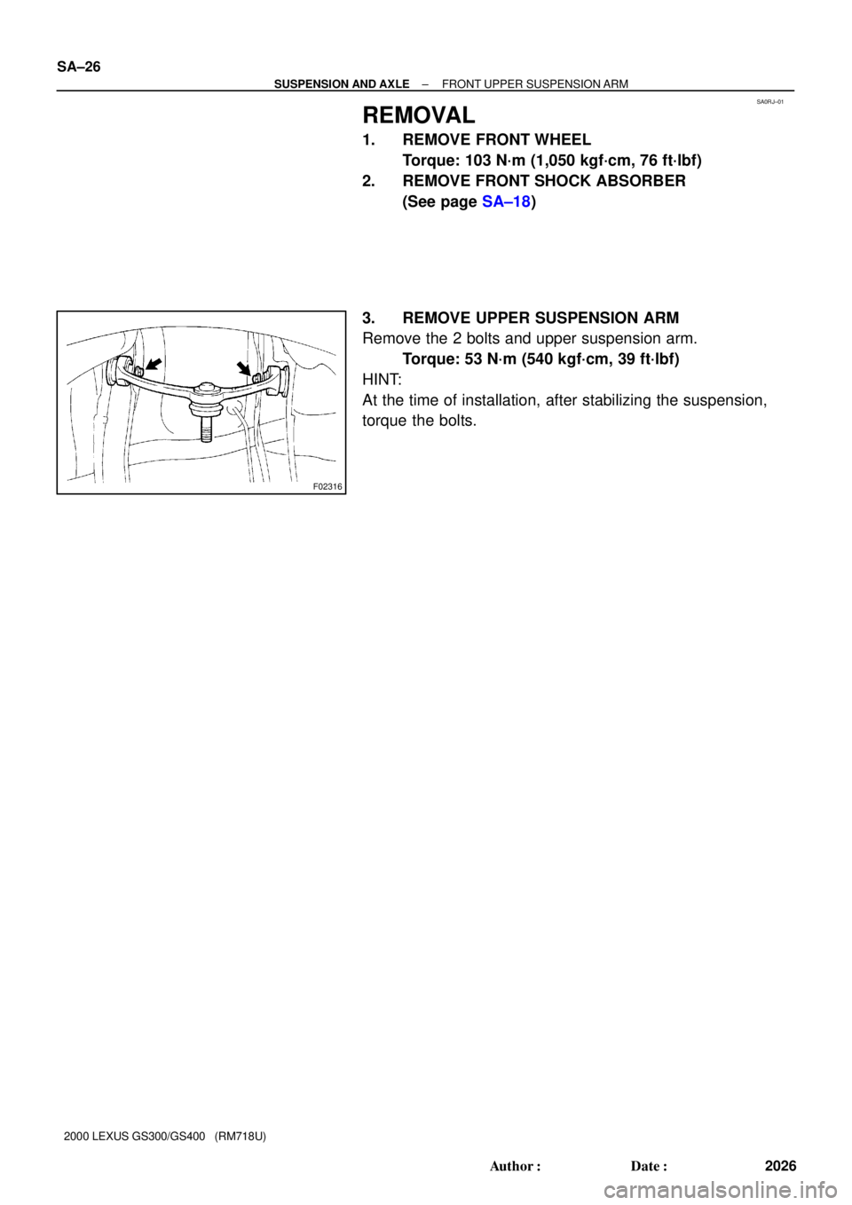
3. REMOVE UPPER SUSPENSION ARM
Remove the 2 bolts and upper suspension arm.
Torque: 53 N´m (540 kgf´cm, 39 ft´lbf)
HINT:
At the time of installation, after stabilizing the suspension,
torque the bolts.
Page 1040 of 1111
SA0RL±01
SA±28
± SUSPENSION AND AXLEFRONT UPPER SUSPENSION ARM
2028 Author�: Date�:
2000 LEXUS GS300/GS400 (RM718U)
INSTALLATION
Installation is in the reverse order of removal (See page SA±26).
AFTER INSTALLATION, CHECK ABS SPEED SENSOR (See page DI±389) AND FRONT WHEEL
ALIGNMENT (See page SA±4)
Page 1042 of 1111

REMOVAL
1. REMOVE FRONT WHEEL
Torque: 103 N´m")
SA0RN±01
F02311
F02312
SST
F02317
F02318
SA±30
± SUSPENSION AND AXLEFRONT LOWER SUSPENSION ARM
2030 Author�: Date�:
2000 LEXUS GS300/GS400 (RM718U)
REMOVAL
1. REMOVE FRONT WHEEL
Torque: 103 N´m (1,050 kgf´cm, 76 ft´lbf)
2. REMOVE ENGINE UNDER COVERS
3. REMOVE BRAKE CALIPER
(a) Remove the 2 bolts and caliper.
Torque: 118 N´m (1,200 kgf´cm, 87 ft´lbf)
(b) Support the brake caliper securely.
(c) Remove the disc.
4. DISCONNECT TIE ROD END
(a) Remove the clip and nut.
Torque: 87 N´m (890 kgf´cm, 64 ft´lbf)
(b) Using SST, disconnect the tie rod end from the steering
knuckle.
SST 09610±20012
5. HID TYPE HEADLIGHT:
DISCONNECT HEIGHT CONTROL SENSOR LINK
FROM SHOCK ABSORBER BRACKET
Remove the nut and disconnect the height control sensor link
from the shock absorber bracket.
Torque: 5.4 N´m (55 kgf´cm, 48 in.´lbf)
6. REMOVE STABILIZER BAR LINK
(a) Remove the bolt and nut, disconnect the stabilizer bar link
from the stabilizer bar.
Torque: 55 N´m (560 kgf´cm, 43 ft´lbf)
(b) Remove the nut and stabilizer bar link.
Torque: 113 N´m (1,150 kgf´cm, 83 ft´lbf)
Page 1045 of 1111
SA0RO±01
± SUSPENSION AND AXLEFRONT LOWER SUSPENSION ARM
SA±33
2033 Author�: Date�:
2000 LEXUS GS300/GS400 (RM718U)
INSTALLATION
Installation is in the reverse order of removal (See page SA±30).
AFTER INSTALLATION, CHECK ABS SPEED SENSOR SIGNAL (See page DI±389) AND FRONT
WHEEL ALIGNMENT (See page SA±4)
Page 1048 of 1111
SA0RR±01
F02311
W00285
SST
R05802
SST SA±36
± SUSPENSION AND AXLEFRONT LOWER BALL JOINT
2036 Author�: Date�:
2000 LEXUS GS300/GS400 (RM718U)
REMOVAL
1. REMOVE FRONT WHEEL
Torque: 103 N´m (1,050 kgf´cm, 76 ft´lbf)
2. REMOVE BRAKE CALIPER
(a) Remove the 2 bolts and caliper.
Torque: 118 N´m (1,200 kgf´cm, 87 ft´lbf)
(b) Support the brake caliper securely.
3. DISCONNECT TIE ROD END FROM LOWER BALL
JOINT
(a) Remove the clip and nut.
Torque: 87 N´m (890 kgf´cm, 64 ft´lbf)
(b) Using SST, disconnect the tie rod end from the lower ball
joint.
SST 09610±20012
4. DISCONNECT LOWER BALL JOINT FROM LOWER
SUSPENSION ARM
(a) Remove the cotter pin and nut.
Torque: 162 N´m (1,650 kgf´cm, 119 ft´lbf)
(b) Using SST, remove the lower ball joint.
SST 09628±62011
5. REMOVE LOWER BALL JOINT FROM STEERING
KNUCKLE
Remove the 2 bolts and lower ball joint.
Torque: 113 N´m (1,150 kgf´cm, 83 ft´lbf)