2000 HONDA CR-V Tail light
[x] Cancel search: Tail lightPage 341 of 1395
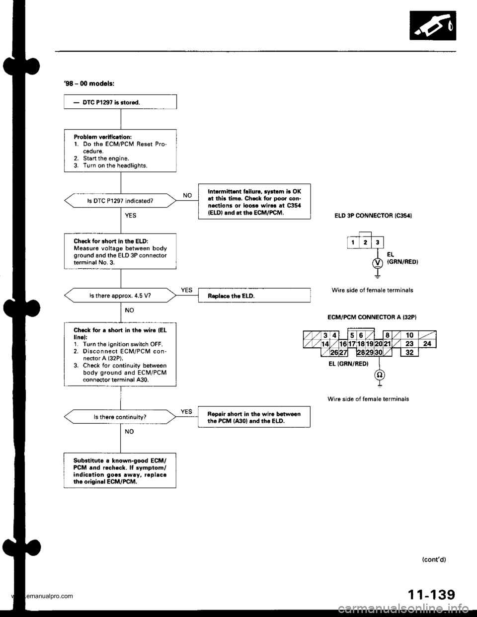
98 - 00 mod6l3:
- OTC P l1€7 is 3tored.
Problcm vcrificrtion:1. Do the ECM/PCM Reset Pro-cedure,2. Start the engine.3. Turn on the headlights.
Intcrmittent tailuro, ryrtom ir OK!t thi3 timo. Ch.ck tor poor con-nectiont or looao wire! at CXl54IELD) rnd at rh6 ECM/PCM,
ls DTC P1297 indicated?
Chock for 3hort in tho ELD:Measure voltage between bodyground and the ELD 3P connectorterminal No.3.
ls there approx. 4.5 V?
Chcck lor a 3horl in tho wiio (EL
linol:1. Turn the ignition switch OFF.2. Disconnect ECM/PCM con-nector A (32P).
3. Check for continuity betweenbody ground and ECM/PCMconn€ctort€rminal A30.
Ropair shon in thc wira botwocntho PcM (A301 rnd rho ELD.
Sub.tituto a known.good ECM/PCM .nd rocheck. ll lymptom/indication gocs .w!y. replsceth6 o.iginal ECM/PCM,
ELD 3P CONNECTOR ICAs4I
f_l,I 2l3l-
l--- r'.
&) iGRN/RED)
T
Wire side of temale terminals
ECM/PCM CONNECTOR A I32P)
Wire sid6 of female terminals
(cont'd)
-13911
www.emanualpro.com
Page 342 of 1395
PGM-FI System
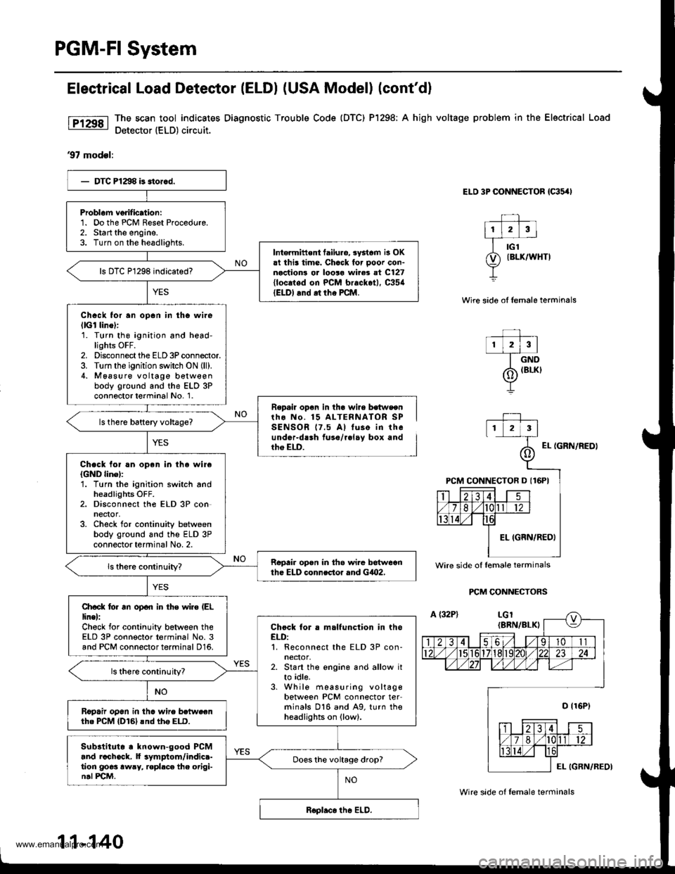
Electrical Load Detestor (ELDI (USA Model) (cont'dl
The scan tool indicates Diagnostic Trouble Code {DTC) Pl298; A high voltage problem in the Electrical Load
Detector (ELD) circuit.
97 modsl:
ELD 3P CONNECTOR {C35,'I
Wire sido oI lemale terminals
r lzlrl--T_ow
/6 IBLKI
Y
Repail op€n in th. wire b€tws€ntho No. 15 ALTERNATOR SPSENSOR 17.5 A) tuse in theunder-dlrh fuso/r.lay box andth6 ELD.EL {GRN/NEDI
PCM CONNECTORS
Problam verification:1. Do the PCM Reset Procedure.2. Start the engine.3. Turn on the headlights.Intermittent tailuro, systcm is OK.t this time. Chack for ooor con-noction! or looro wire3 at C127{locaied on PCM brackot), C35{{ELDI and .t tho PCM.
Chack for an opan in tho wilellGl linol:1. Turn thg ignition and head-lights OFF.2. Disconnect the ELD 3P connector.3. Turn the ignition switch ON {ll).4. M6asure voltage b€tw€enbody ground and the ELD 3Pconnoctor terminal No. 1.
Chock lol !n open in the wireIGND linel:'1. Turn the ignition switch andheadlights OFF.2. Disconnect the ELD 3P conneqor,3. Check for continuity betweenbody ground and the ELD 3Pconnector terminal No. 2.
Ropair opon in th6 wi.e betweonth. ELD connector rnd GiO2,
Ch.ck lo. an open in th€ wiro (EL
line):Check for continuity between theELD 3P connector terminal No. 3and PCM connector terminal 016.
Chock for . malfunction in theELD:1. Reconnect the ELD 3P con-neclor,2. Start the engine and allow itto idle.3. While measuring voltagebetween PCM connector terminals 016 and A9. turn theheadlights on (low).
ls there continuityT
R6pafu op6n in tho wire betweenthe PCM {D161snd th6 ELD.
Subltituto . known-good PCMand rachock, f symptom/indic.-tion goes awry, ropl.ce the origi-n.l PCM.
Does the voltage drop?
Wire side of lemale terminals
11-140
Wire side of lemale terminals
www.emanualpro.com
Page 401 of 1395
Emission Control System
System Description
The emission control system includes, a Three Way
Catalytic Converter {TWC), Positive Crankcase Ventilation
(PCV) svstem and Evaporative Emission (€VAP) Control
system. The emission control system is designed to meet
federal and state emission standards.
Tailpipe Emission
Inspsction
!@ Do not smoke during this procsdura. Keep
any open tlame away from your work area.
1. Start the engine. Hold the engine at 3,000 rpm with
no load (in Park or neutral) until the radiator fan
comes on, then let it idle,
Connect a tachometer.
Check and, if necessary, adjust the idle speed, (see
page 11-169, 170).
Warm up and calibrate the CO meter according to the
meter manufacturer's instructions.
Check idle CO with the headlights, heater blower, rear
window defogger, cooling fan, and air conditioner off.
(Canada) Pull the parking brake lever up. Start the
engine, then check that the headlights are off.
CO meter should indicate 0.1% maximum.
4.
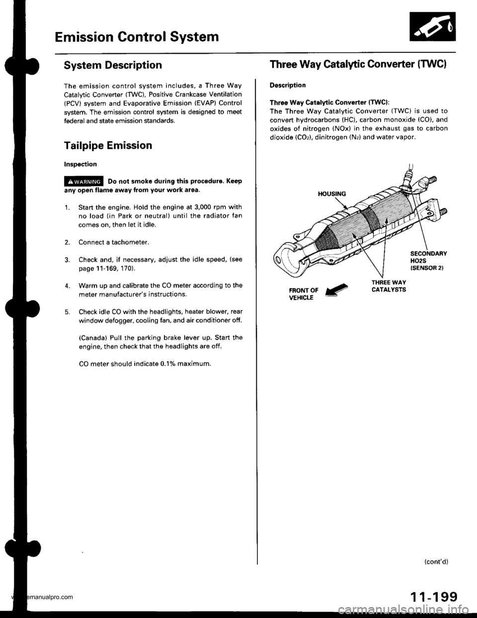
Three Way Catalytic Converter (TWCI
DsscriDtion
Three Way Catalytic Convertsr lTwcl:
The Three wav Catalvtic Converter (TWC) is used to
convert hydrocarbons (HC), carbon monoxide (CO), and
oxides of nitrogen (NOx) in the exhaust gas to carbon
dioxide (COr), dinitrogen (Nr) and water vapor,
{cont'd)
1 1-199
www.emanualpro.com
Page 612 of 1395
Electrical Troubleshooting ('98 - 00 Models)
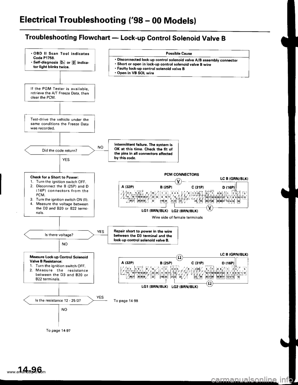
Troubleshooting Flowchart - Lock-up Control Sotenoid Valve B
Possibl€ Cause
. Disconnected lock-up control solenoid valve A/8 assembly connector. Short or open in lock-up control solenoid valve B wire. Fauhy lock-up control solenoid valve B. Open in VB SOL wir€
PCM CONNECTORSLC B {GRN/8LKI
LG1{BRN/BLK} I-G2{BRN/BLK)
Wire side of female terminals
A {32P1
To page 14 98
.OBD ll Scan Tool indicatesCode P'l758.. Sell-diagnosis Dl or E indica-tor light blinks twic€.
lf the PGM Tester is available,relrieve the A,/T Freeze Data, thenclear the PCM-
Test-drive the vehicle under thesame conditions the Freeze Data
Interm ittant tailure. The lystem isOK at this time. Check the tii ottho pin3 in all connectors athedby this code.
Did the code return?
Check for a Short to Pow€r:1. Turn the ignition switch OFF.2. Disconnect the B 125P) and D(16P) con nectors lrom thePCM.3. Turn the ignition switch ON 1ll).4. Measure the voltage betlveenthe D3 and 820 or 822 termi-nals.
Repair shon to power in the wirebetween tho D3 terminal and thelook-up control solenoid valve B.
Measure Lock-up Control SolanoidValve B Resistanc€:1. Turn the ignition switch OFF.2. Measure the resistancebetween the D3 and 820 or822 terminals.
ls the resistance 12 - 25 O?
To page 14-97
www.emanualpro.com
Page 622 of 1395
Electrical Troubleshooting ('98 - 00 Models)
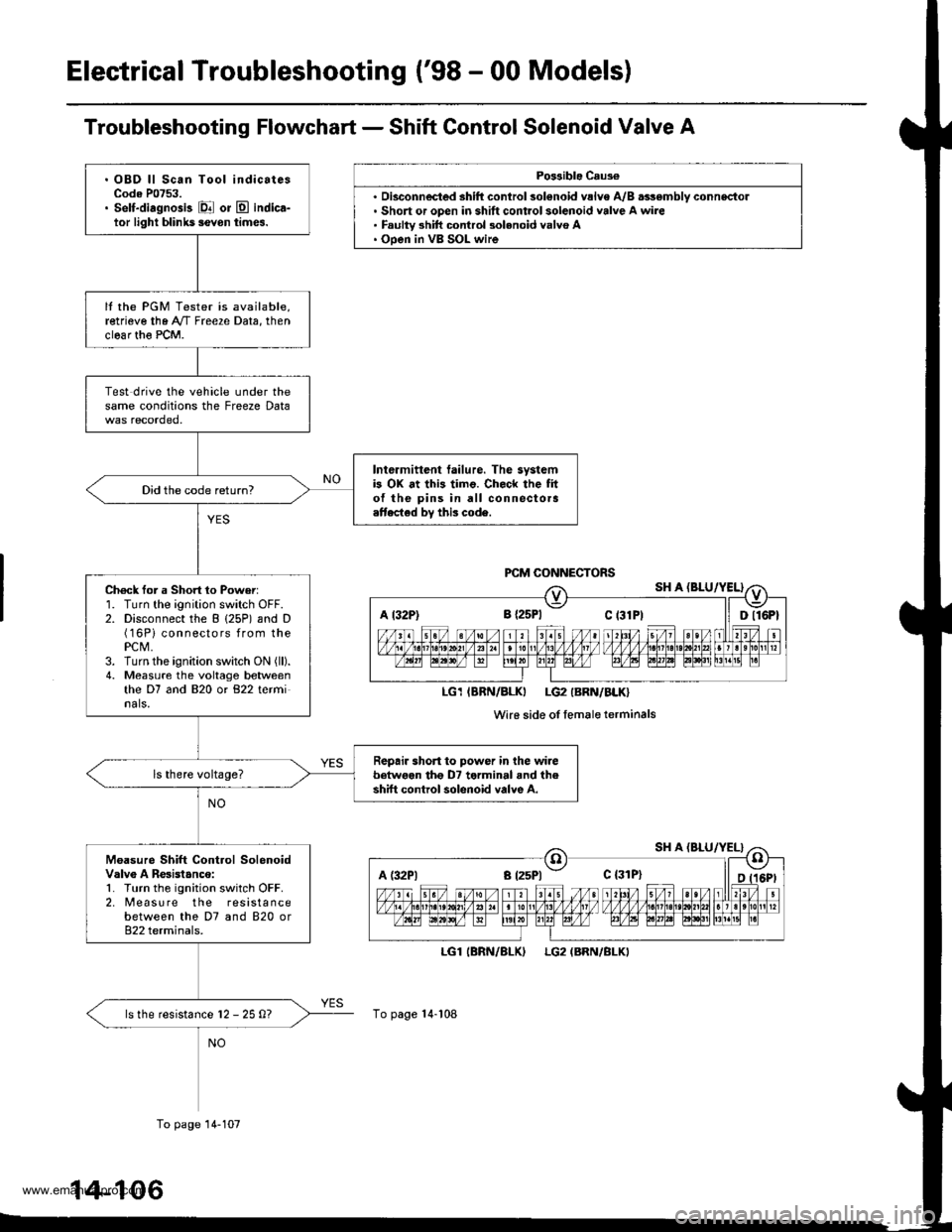
Troubleshooting Flowchart - Shift Control Solenoid Valve A
Po$ible Caus€
'. Short or open in shift control solenoid valve A wire. Faulty 3hift control 3olenoid valvo A. Ooen in VB SOL wire
LGl
To page 14-108
(BRN/BLKILG2 (BRN/BLKI
A t32P) 8 {2sPl Ct3lPt ll Dll6Pt
LG1IBRN/BLKI LG2IBRN/BLK}
Wi16 side of femaleterminals
A (:l2Pl a t25Pl - c {31P}
. OBD ll Scan Tool indicatesCode P0753.. Self-diagnosis El or E indica-tor light blihk5 ievon times.
It the PGM Tester is available,retrieve the A"/T Freeze Data, thenclear th€ PCM.
Test drive the vehicle under thesame conditions the Freeze Data
Intermittent tailure. The systemb OX at this timo. Check the fito{ the pins in all connectora.ttected by this code.
Did the code return?
Ch6ck for a Short 1o Power:1. Turn the ignition switch OFF.2. Disconnect the B (25P) and D(16Pi connectors from thePCM,3. Turn the ignition switch ON (ll).
4. Measure the voltage betweenthe D7 and 820 or 822 terminals.
Repair short to power in the wirebetwoen tho D7 terminal and theshift control solenoid valve A.
Moasure Shift Control SolenoidValv6 A Resistanco:1. Turn the ignition switch OFF.2. [reasu re the resistancebetween the D7 and 820 or822 terminals.
ls the resistance l2 - 25 0?
To page 14-107
14-106
www.emanualpro.com
Page 630 of 1395
Electrical Troubleshooting ('98 - 00 Modelsl
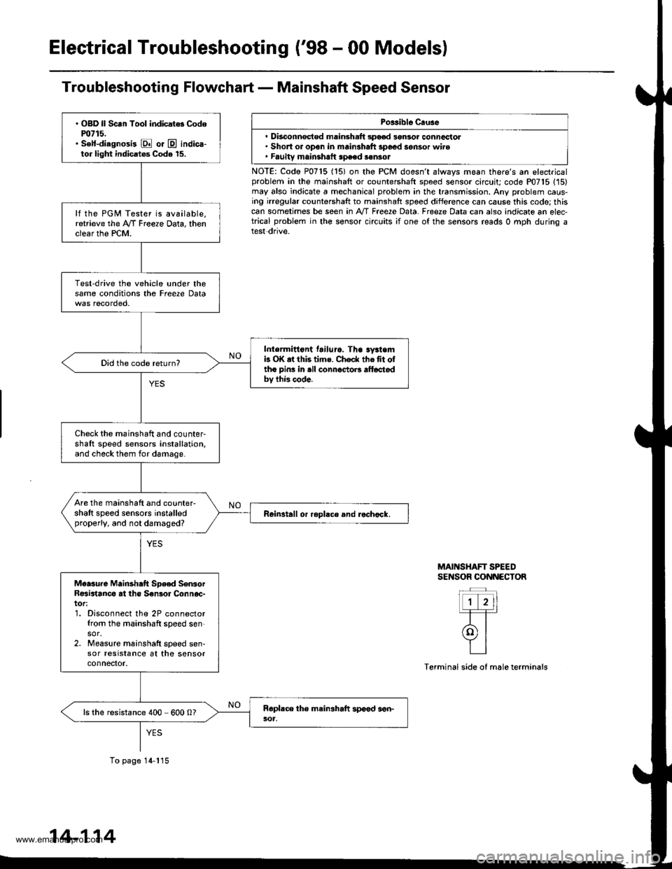
Troubleshooting Flowchart - Mainshaft Speed Sensor
Porsible Cruse
. Disconnsct€d msinsh.ft 3pood 3gnlor conncctol. Short or open in mainshaft 3poed sensor wire. Faultv mainshrtt speed sonsot
NOTE: Codo P0715 (15) on the PCM doesn't always moan there's an electricalproblem in the mainshaft or countershaft speed sensor circuit; code P07'15 (15)may also indicate a mechanical problem in the transmission. Any problem caus-ing irregular countershaft to mainshaft spoed difference can cause this codo; thiscan sometimes be seen in A'/T Free2e Data. Freeze Data can also indicate an elec-trical problem in the sensor circuits ;f one of the sensors reads 0 mph during atest dnve.
MAINSHAFT SPEEDSENSOR CONNECTOR
Terminal side of male terminals
. OBD ll Scan Tool indicat$ Codem715.. S€lf-diagnosi3 E or @ indica-tor light indicatos Code 15.
lf the PGM Tester is available,retrieve the A/f Freeze Data, thenclear the PCM.
Test-drive the vehicle under thesame conditions the Freere Data
Intermittont tailuro. Tha sy3temb OK at this tims. Check thefit oftho pins in .ll connoctoB alt6ctedbv this code.
Did the code return?
Check the mainshaft and counter-shaft speed sensors installation,and check them for damage.
Are the mainshaft and counter-shaft speed sensors installedproperly, and not damaged?Reinstall or ropllce and rochock.
Moasure Mainshatt Spe€d SenrorR€sirtanco at ths S€nsol Connoc-tor:1. Disconnect the 2P connectorfrom the mainshaft speed sensor.2. Measure mainshatt speed sen-sor resrstance at the sensorconnefior.
ls the resistance 400 600 0?
To page 14-115
14-114
www.emanualpro.com
Page 633 of 1395
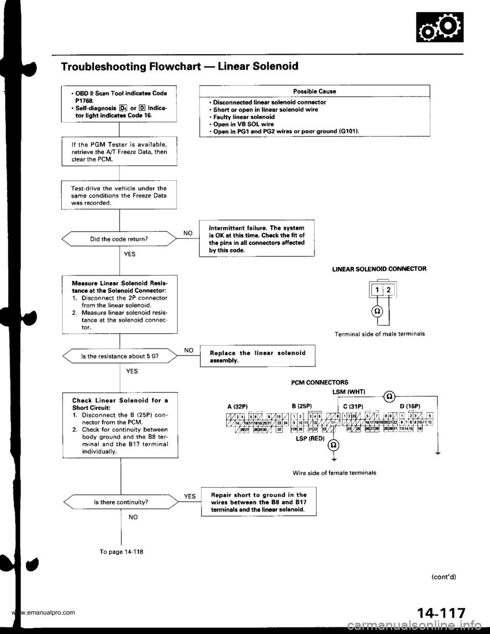
Po$ible Cau3e
' Disconnectsd linoar solenoid conneclol. Short or open in linear solenoid wire. Faulty linear 3olenoid. Open in VB SOL wire. Open in PGI and PG2 wires or poot g.ound {G101).
. OBD ll Scan Tool indic{t.. CodsP1768.. selt-diagnosis El or E indica-tor light indicrt.. Codo 16.
lf the PGM Tester is available.retrieve the A/T Freeze Data, thenclear the PCM.
Test drive the vehicle under thesame conditions the Freeze Data
Inlermittont tailure, The 3yrtomis OK at thb time. Check the tit otlhe oins in all connectoE affoctodby this code.
Did the code return?
Meaaure Linear Solenoid R€sis-tanc€ at the Solenoid Connector:1. Disconnect the 2P connectorfrom the linear solenoid-2. Measure linear solenoid resis-tance at the solenoid connector.
ls the resistance about 5 O?
Chock Lino.r Sol.noid to. aShort Circuh:1. Disconnect the B (25P) con-nector lrom the PCM.2. Check tor continuity betweenbody ground and the 88 ter-minal and the 817 terminalindividually.
Repair 3ho to ground in thewires belween the 88 rnd B17terminals and tho linaar 3olenoid.ls there continuity?
A l32PtB {2sP)
LSP (REDI
To page 14-118
SOLENOID COiINECTOR
t-rtt
(9l
tt
LINEAR
Terminal side ol male terminals
wire side oI temale terminals
(cont'd)
14-117
www.emanualpro.com
Page 1005 of 1395
Doors
(cont'd)
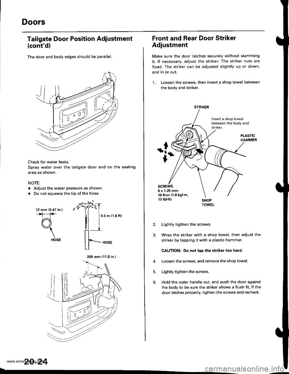
The door and body edges should be parallel.
Check for water leaks.
Spray water over the tailgate door and on the sealing
area as shown.
NOTE:
. Adjust the water pressure as shown.
. Do not squeeze the tip ofthe hose.
Tailgate Door Position Adiustment
-€*4
,'r)"C
II
0.5 m {1.6 ft}
20-24
l2 mm (0.47 in.).*1:]*
d3"1
HOSE
300 mm {11.8 in.l
Front and Rear Door Striker
Adjustment
Make sure the door latches securely without slamming
it, lf necessary, adjust the striker: The striker nuts are
fixed. The striker can be adjusted slightly up or down,
and in or out.
1. Loosen the screws, then insert a shop towel between
the body and striker.
Insert a shop towelbetween the body and
scREws8 x 1 .25 mm18 N.m (1.8 kgt.m,13 rbf.ft)
2.
J.
Lightly tighten the screws.
Wrap the striker with a shop towel, then adjust the
striker by tapping it with a plastic hammer.
CAUTION: Do not tap the striksr loo hard.
Loosen the screws. and remove the shop towel.
Lightly tighten the screws.
Hold the outer handle out, and push the door against
the body to be sure the striker allows a flush fit, lf the
door latches properly. tighten the screws and recheck.
4.
5.
6.
STRIKER
www.emanualpro.com