Page 156 of 1395
Pistons and Crankshaft
Removal (cont'dl
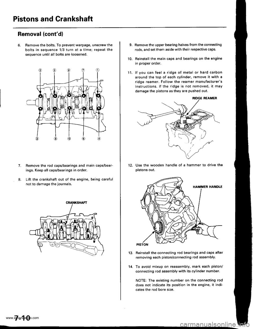
6. Remove the bolts. To prevent warpage, unscrew the
bolts in sequence 1/3 turn at a time; repeat the
sequence until all bolts are loosened.
Remove the rod caps/bearings and main caps/bear-
ings, Keep all caps/bearings in order
Lift the crankshaft out of the engine. being careful
not to damage the journals.
7.
7-10
9.
10.
Remove the upper bearing halves from the connecting
rods, and set them aside with their respective caps.
Reinstall the main caps and bearings on the engine
in proper order.
lf you can feel a ridge of metal or hard carbon
around the top of each cvlinder, remove it with a
ridge reamer. Follow the reamer manufacturer's
instructions. lf the ridge is not removed, it may
damage the pistons as they 8re pushed out.
12.
11.
14.
Use the wooden handle of a hammer to drive the
pistons out.
13.Reinstall the connecting rod bearings and caps after
removing each piston/connecting rod assembly.
To avoid mixup on reassembly, mark each piston/
connecting rod assembly with its cylinder number.
NOTE: The existing number on the connecting rod
does not indicate its position in the engine, it indi-
cates the rod bore size.
www.emanualpro.com
Page 157 of 1395
Crankshaft
Inspection
1. Clean the crankshaft oil passages with pipe cleaners
or a suitable brush.
2. Check the keyway and threads.
Alignment
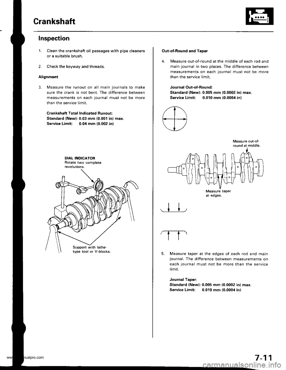
3. Measure the runout on all main journals to make
sure the crank is not bent. The difference between
measurements on each journal must not be more
than the service limit.
Crankshaft Total Indicated Runout:
Standard lNew):0.03 mm (0.001 in) max.
Service Limit: 0.04 mm {0.002 in)
DIAL INDICATORRotate two completerevolut|ons.
Suppon with lathe-lype tool or V-blocks.
Out-of-Round and TaDer
4. Measure out-of-round at the middle of each rod and
main journal in two places. The difference between
measurements on each lournal must not be more
than the service limit.
Journal Out-of-Round:
Standard (Newl:0.005 mm 10.0002 inl max.
Service Limit: 0.010 mm (0.000i1in)
Measure out-ol'round at middle.
Measure taperat edges.
5. Measure taper at the edges of each rod and mainjournal. The difference between measurements on
each iournal must not be more than the service
limit.
Journal Taperi
Standard {Newl: 0.005 mm 10.0002 inl max.
Service Limit: 0.010 mm (0.0004 inl
7-11
www.emanualpro.com
Page 160 of 1395
Piston PinsConnecting Rods
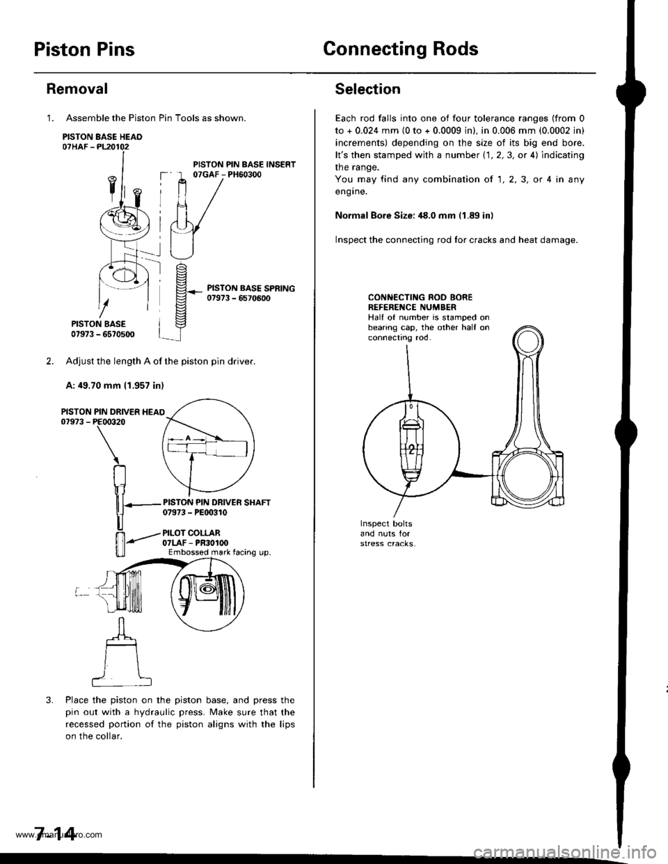
Assemble the Piston Pin Tools as shown.
PISTON BASE HEAO07HAF -PL20102
PISTON BASE07973 - 6570500
Adjust the length A of the piston pin dflver.
A: 49.70 mm 11.957 in)
PIN DRIVER HEAIPE00320
\
RIr1
nT---
u
ffi-"""-
u_ll
3. Place the piston on the piston base, and press the
pin out with a hydraulic press. Make sure that the
recessed portion of the piston aligns with the lips
on the collar.
7-14
Removal
1.
PISTON07973 -
PISTON PIN BASE INSERT07GAF - PH60300
PISTON PIN DRIVER SHAFT07973 - PEt 0310
PILOT COLLAR07LAF - PR30100Embossod mark facing up.
Selection
Each rod falls into one of four tolerance ranges (from 0
to + 0.024 mm {0 to + 0.0009 in). in 0.006 mm (0.0002 in)
increments) depending on the size of its big end bore.
lt's then stamped with a number 1.1.2,3, or 4) indicating
the range.
You may find any combination ot 1,2,3, or 4 in any
engrne.
Normal Bore Size: ,18.0 mm (1.89 in)
Inspect the connecting rod for cracks and heat damage.
CONNECTING ROD BOREREFENENCE NUMBERHalf of number is stamped onbearing cap, the other half onconnectno roo.
www.emanualpro.com
Page 162 of 1395
Piston Pins
lMeasure the diameter of the piston pin.
Piston Pin Diameter:
Standard lNewl: 20.996 - 21.000 mm
{0.8266 - 0.8268 in}
20.998 - 21.002 mm(0.8267 - 0.8268 in)
Inspection
1.
Oversize:
2. Zeto the dial indicator to the piston pin diameter.
7-16
3. Measure the piston pin to piston clearance. lf the
piston pin clearance is greater than 0.024 mm
(0.0009 inL remeasure using an oversized piston pin.
NOIE: All replacement piston pins are oversize.
Piston Pin-to-Piston Clearance:
Standard lNewl: 0.010 - 0.017 mm
10.0004 - 0.0007 in)
Check the difference betlveen the piston pin diame-
ter and the connecting rod small end diameter.
Piston Pin-to-Connecting Rod Interference:
Standard (New): 0.015 - 0.032 mm(0.0006 - 0.0013 inl
4.
www.emanualpro.com
Page 171 of 1395
Engine Lubrication
Speciaf Tools .......... ...".""'8-2
lllustrated Index ........... .'...8-3
Engine Oil
Inspection ............'..'...'..' 8-4
Replacement ............................'........... 8-4
OilFilter
Rep1acement........................................ 8-5
Oil Pressure Switch
Testing ".....8-7
Oil Pressure
Testing ....'.' 8-7
OilPump
Overhaul..... ...........,......... 8-8
Removal/lnspection/lnstallation ....'.' 8-9
www.emanualpro.com
Page 174 of 1395
Engine Oil
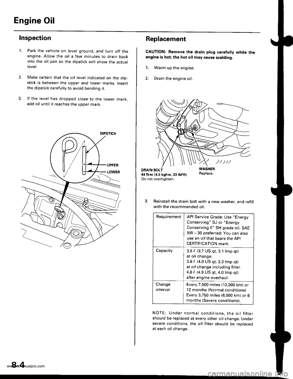
Inspection
2.
1.Park the vehicle on level ground, and turn off theengine. Allow the oil a few minutes to drain backinto the oil pan so the dipstick will show the actuallevet,
Make certain that the oil level indicated on the dip-stick is between the upper and lower marks. Insertthe dipstick carefully to avoid bending it.
lf the level has dropped close to the lower mark,add oil until it reaches the upper mark.
8-4
Replacement
CAUTION: Remove the drain plug caretuly white theengino is hot; the hot oil may cause scalding.
1. Warm up the engine.
2. Drain the engine oil.
WASHERR€place.ORAIN BOL4il N.m {4.5 kgtm,33 lbf.ft)Do not overtighten.
3. Reinstall the drain bolt with a new washer, and refill
with the recommended oil.
RequirementAPI Service Grade: Use "Energy
Conserving " SJ or "Energy
Conserving ll" SH grade oil. SAE
5W - 30 preferred: You can also
use an oil that bears the API
CERTIFICATION mark.
Capacity3.5 { (3.7 US qt,3.1 lmp qt)
at oil change.
3.8 / (4.0 US qt,3.3 lmp qr)
at oil change including filter.
4.6 { (4.9 US qt, 4.0 lmp qt)
after engine overhaul.
Change
Inlerval
Every 7,500 miles (12,000 km) or12 months (Normal conditions)
Every 3,750 miles (6,000 km) or 6months (Severe conditions).
NOTE: Under normal conditions, the oil filtershould be replaced at every other oil change. Undersevere conditions, the oil filter should be replacedat each oil change.
www.emanualpro.com
Page 177 of 1395
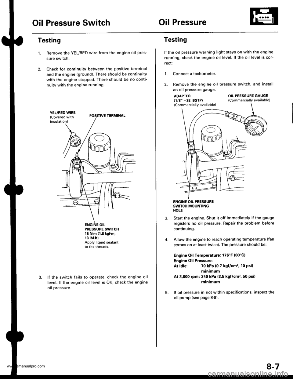
Oil Pressure SwitchOil Pressure
Testing
Remove the YEL/RED wire from the engine oil pres-
sure swrtcn.
Check for continuity between the positive terminal
and the engine {ground). There should be continuity
with the engine stopped. There should be no conti-
nuity with the engine running.
L
PRESSURE SWTCH18 N.m {1.8 kgf.m,13 tbr.ftlApply liquid sealantto the threads,
lf the switch fails
level. lf the engine
orl pressure.
to operate, check the engine oil
oil level is OK, check the engine
Testing
lf the oil pressure warning light stays on with the engine
running, check the engine oil level. lf the oil level is cor-
rect:
L Connect a tachometer.
2. Remove the engine oil
an oil pressure gauge.
ADAPTER(1/8" - 28, BSTP)(Commercially available)
pressure switch. and install
OIL PRESSURE GAUGE
{Commercially available)
4.
ENGINE OIL PRESSURESWTTCH MOUNNNGHOt-E
Start the engine. Shut it off immedjately if the gauge
registers no oil pressure. Repair the problem before
continuing.
Allow the engine to reach operating temperature (fan
comes on at least twice). The pressure should be:
Engino Oil Temperature: 176'F (80'C)
Engine Oil Pressure:
At ldle:70 kPa (0.7 kgt/cm'�, 10 psil
minimum
Ai 3,000 rpm: 3/r0 kPa {3.5 kgt/cm', 50 psi)
minimum
lf oil pressure in not within specifications, inspect the
oil pump (see page 8-9).
8-7
www.emanualpro.com
Page 188 of 1395
'97 - 98 U.S. models (Except Californial:'99 - 00 models:
GASKETReplace.
SELF.LOCXING NUTl0 x 1.25 mm33 N.m 13.4 kgl.m, 24 lbtft)Replace.
SELF.LOCKING NUT8 x 1.25 mm22 N.m (2.2 kgf.m, 16 lbl.ft)Replace.Tighten the nuts in steps,alternating side to side.
SECONDARY HEATEDOXYGEN SENSOR{SECONDARY HO2SI4il N.m 14.5 kgl.m,33 tbf.ftl
THREE WAY CATALYTICCONVERTER (TWCI
lnspection, see section 11
MUFFLER
PRIMABY HEATEDOXYGEN SENSOR(PRTMARY HO2S)44 N.m (4.5 kgf.m,33 tbf.ftl
GASKETSReplace.
SELF-LOCKING NUT8 x 1.25 mm16 N.m 11.6 kgf.m,12 tbf.fttReplace.
SELF.LOCKING NUT
8 x 1.25 mm22 N,m 12,2 kgi'm,16 tbf.ftlReplace.Tighten the nuts in
steps, alternatingside-to-sade.
9.8 N.m {1.0 kgf.m,7.2 rbf.ft)
x 1.0 mm
NUT10 x 1.25 mm5a N.m (5.5 kgl.m,40 lbf ftlReplace.
www.emanualpro.com