2000 HONDA CR-V Air Control
[x] Cancel search: Air ControlPage 425 of 1395
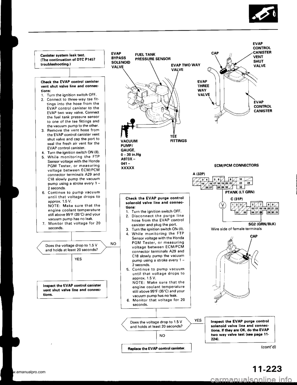
Canbter system leak test
{The continuation of DTC P1457
trouble3hootin9.)
Chock the EVAP control canistervent shut valve line and connoc'
tonS:1. Turn the ignition switch OFF
2. Connect to three'way tee fit_
tings into the hose from the
EVAP control canister to the
EVAP two way valve. Connect
the fuel tank pressure sensor
to one of the tee fittings and
the vacuum PumP to the other'
3. Remove the vent hose from
the EVAP control canister vent
shut valve and cap the Pon to
seal the fresh air vent Ior the
EVAP control canister.4. Turn the ignition switch ON (ll).
5. While monitoring the FTP
Sensor voltage with the Honda
PGM Tester, or measurangvoltage between ECM/PCM
connector terminals A29 and
C18 slowly PumP the vacuumpump using a stroke every 1 -
2 seconds.6. Continue to PumP vacuum
until that voltage droPs to
approx. 1.5 V.NOTE: Make sure that the
engine coolant temPeraturestillabove 95'F (35'Cland Yourvacuum PumP has no leak
7. Monitor that voltage for 20
seconds.
Check the EVAP Pu.ge control
solenoid valve line and connec-
tions:1. Turn the ignition switch OFF.
2. Disconnect the Purge lane
hose from the EVAP control
canister and Plug the Port3. Turn the ignition switch ON (lli.
4. While monitoring the FTP
Sensor voltage with the Honda
PGM Tester, or measuringvoltage between ECM/PCM
connector terminals A29 and
Cl8 slowly PumP the vacuumpump using a stroke every 1 -
2 seconds.5. Continue to pump vacuum
until that voltage droPs to
approx. 1-5 V.NOTE: Make sure that the
engine coolant temPeraturestill above 95'F (35"C) and Yourvacuum pump has no leak-
6. Monitor that voltage tor 20
seconds.
Doesthe voltage drop to 1.5 V
and holds at least 20 seconds?
lGp€ct the EVAP control cani3tel
vent 3hut valvo line and connec_
tion5.
Inlpect tho EVAP Putge control
solenoid valvo line and connec'
tion3. It th6y lro OK, do the EVAP
two way valve te3t (seo page 11-
2211.
Does the voltage drop to 1.5 V
and holds at least 20 seconds?
Reolace the EVAP conirol canister.
EVAPBYPASSSOLENOIDVALVE
FUEL TANK
EVAPCONTROL
VENTSHUTVALVE
EVAPCONTROLCANISTER
SENSOR
EVAP TWO WAYVALVE
EVAPTHREE
VALVE
ttrrL
ta
VACUUMPUMP/GAUGE,0 - 30 in.HgA973X -
041 -
XXXXX
FITTINGS
ECM/PCM CONNECTORS
A {32P)
PTANK ILT GRN)
c (31Pt
SG2 {GRN/BLK)
Wire side of female terminals
{cont'd)
11-223
www.emanualpro.com
Page 517 of 1395

Automatic Transmission
Special Tools . 14'2OescriptionGeneral Operation . .... 14 3Power Flow . . .. '14_6
Electronic Control System .. .. . . .. .14_15Hydraulic Control .. 14 24Hydraulic Flow....-....... .. . .... .. .. . 14_29Lock'up Syslem .. .'t4'39Electrical SystemComponenl Locdlrons 14 45
PCM Circuil Dragram (A/T Control Svstem)'97 Model ....................... . . .. - . ... .14-46'98Model ................. . ... .. .. .1450'99 00Models.... . .... . . . 1452
PCM Terminal Voltage/Measuring ConditionsA"/T Control System-'97Model ...... ..14'48A,/T Control System -'98 00 Models . . .. . . 14 54
Troubleshooting Procedures .. ..... ... - 14_56Svmotom to comoonent CharlEiectr,cal Syslem -'97 Model . . 14 60Electrical System -'98 - OO Models . .. . . 14_62Electrical Troubleshooting ('97 Model)Troubleshooting Flowaharts .... ..... . .. . . 14_64
Electrical Troubleshooting ('98 - 00 Models)Troubleshootinq Flowclt"n" .... . ....- . .14-93ElectricalTroublesliooting('99 00Models)Troubleshootino FlowchartO/D OFF Indicator Light Does Not Come On 14 131
O/D OFF Indicator Liaht On ConstantlY . . . .1!-132O/D OFF Indicator Light Does Not Come OnEven Though O/D Switch ls Pressed . .... - 14_133
Lock up Control Solenoid Valve A,/B AssemblyTest....................-......... . .14-135Replacement . .ll_135Shifr ControlSolenoid Valve Ay'B Assembl,Test .............................. . .. 14-136
Replacement..............- . .14'136Linear Solenoid AssemblYTest.............................................. .. .... . 14_137Replacement .. . 14138Marnshaftlcountershafl Speed SensorsReplacement ...-... 14_138A/T Gear Position SwitchTest ..........................-... . .. 14-139ReplacementA/T Gear Positionlndicator.................. 14-140
Valve Eodynepair ............................... ..... . . .. - . .. ... 14 192
Assembly .................... .. 1{_193
Valve CapsDesciiption....-........................ .. ...... 14194
tnspeition ................... .. 14' 195
N4ain Valve BodyDisassembly/lnspection/Reassemblv - ...... .. 14_196
Secondarv Valve BodYDisassemblv4nspectron/ReassemblY .. . 14 198
Reoulator Valve Bodvbisassembtv,lnspiction/Reassemblv . 14199
Servo EodvDisassembly/lnspection/Reassembly ... ....14'200
Lock'uo Valve BodYDis;ssembly/lnspection/Reassembly .... . 14_201
MainshaftDisassembly/lnspection/Reassembly .. .. .. ..14'202
Inspection ....-.............. ..11_203
Sealing RingsReilaceient ...... ..... . 14'204
CountershaftDisassembly/lnspection/Reassembly .. . . . . . 11-205
Disassembly/Reassemb|y . . ........ ...... . .. 14_206Inspedron ................ . .... . 14 207
One wav ClutchDisassembly/lnspection/ReassemblY ... 11_209
Sub-shaftDisassembly/lnspection/Reassembly ... . .. . 14-210
oisassembly/Re6ssembly . . ... .-...... . . ..14-211
Sub-shaft BearingsReplacement .......14'212
Clutchllfustrated Index .......... . . .14-213
Disassembly .... .. .....14-216Reassembfy .... . .. .. . 14'218
Differentialllfustrated Index " 14-222Backlash Inspection . .... . .14'223
Bearing Repiacement .. 11-223
Differe-ntial Carrier Replacement .. .. . . . .. ..11-2?4
OifSeal Replacement. . .. 14'225
Side Clearance lnspection . . - .. ... . - ...... . .. 11'226
Transmission Housing BearingsMainshaJVCountershaft EearingsRepfacement .......14221Sub'siralt Eearing Replacement . . . . . . . . . ..11'224
Toroue Converter Housing BearingsMainshattEearing/OilSe6lReplacement . .. l4229
Countershaft Bea;ing Replacement.. .... .. ..14-230
Input Test - '97 - 98 ModelsInput Test '99 - 00 Models
Symptom to-Component ChartHydraulic System ...............
Checking
Removal ...,lllustrated Index (4WD)
Interlock SystemInterlock ControlUnit lnputTest. -..... -.. .... . - 14 144* Key Interlock Solenoid Test .- .. . . . - . . . ..... 14_146* Shift Lock Solenoid Test ..............-.-. . .. . ... .... 14 147*Shift LockSolenoidReplacement...... .. . .. .. 14 148* park pin Switch Test ......... 14 119' Park Pin Switch Replacement- '97 - 98 Models ....... 14-150* Park Pin Swirch/Over Drive (O/Di SwitchReplacemenl '99-00Models . .. 14_151over-Drive (O/D) Switch {'99 00 [4odels]Test........_..................... .......14-152Hydr.ulic System
..............._............... t4 142.................................. 14-143
Control Lever AssemblyR6placement ......,.,Reverse ldler Gear
lllustrated lndex
.......... 14-230
14 231
11-231
1nsta1|ation ..................Park StopInspeclion/AdjustmenlTransfer AssemblY.......14.232
RoadTest.............-.... ........ .StallSpeedTest ....._........................ ....... 14-159Fluid Level......_................... 14'160
Disessembly .................... 14-235Transfer Drive Gear BearingReplacementTrans{er Driven Gesf Shaft BearingReplacementTransfer Housing Roller BearingReplacementTransfer Cov€r A Bearing Outer RaceReplacementTransfer Housing Bearing Outer RaceReplacement ......-..,,,,,.....ReassemblvTransmassaonBeassembly ... -.. .... .14 250
Torque Converier/Drive Plate . .-. .... .. . ... .....14_258
Transmissionlnstatlation .................. ....... 14'259
Cooler Flushing . . ......11-261ATF Cooler HosesConnection.................. ....... 14-266I Shift LeverRemoval/lnstallation . .. 14'261
Disassemblv/Reassemblv - '97 - 98 Models . . 14_264
Disassembli/Reassemblv -'99 - 00 Models . 14-269
Over'Orive (O/D) Switch WireClearanceAdjustment. - ... . . . .. .. . 14'270
Detent Spring Replscement . . -.. ... .14'271*Shift CableAdiustment ....... 14'272
Repfacement.............. . 11'273
14 15711-237
11-237
14-238
$-234
11-23914-240
Transmigrion
Inspeclron ....., ...........Transfer AssemblyRemova1,.,,,..............,lnstallalion ........... .. ...Transmission
14 164
14-16514,167
14-169
End Cover/Transmissio . 14'174Transmission Housing .... ... .. . . .... .. 14-176Torque Converter Housingly'alve Body.. - ... -. 14 178
lllustrated lndex (2WD)End Cover/Transmissio ....... 14 180Transmission Housing . . ... . .. .... ... 14'182Torque Convener Housing/r'alve Body ......- 14-184
End CovefRemovat ...................... ....... 14'186Transmission HousingRemoval ...................... .. 14_188Torque Convener HousingA/alve BodYRemovat ................-..... .-..... 14-190
www.emanualpro.com
Page 580 of 1395
Electrical Troubleshooting ('97 Model)
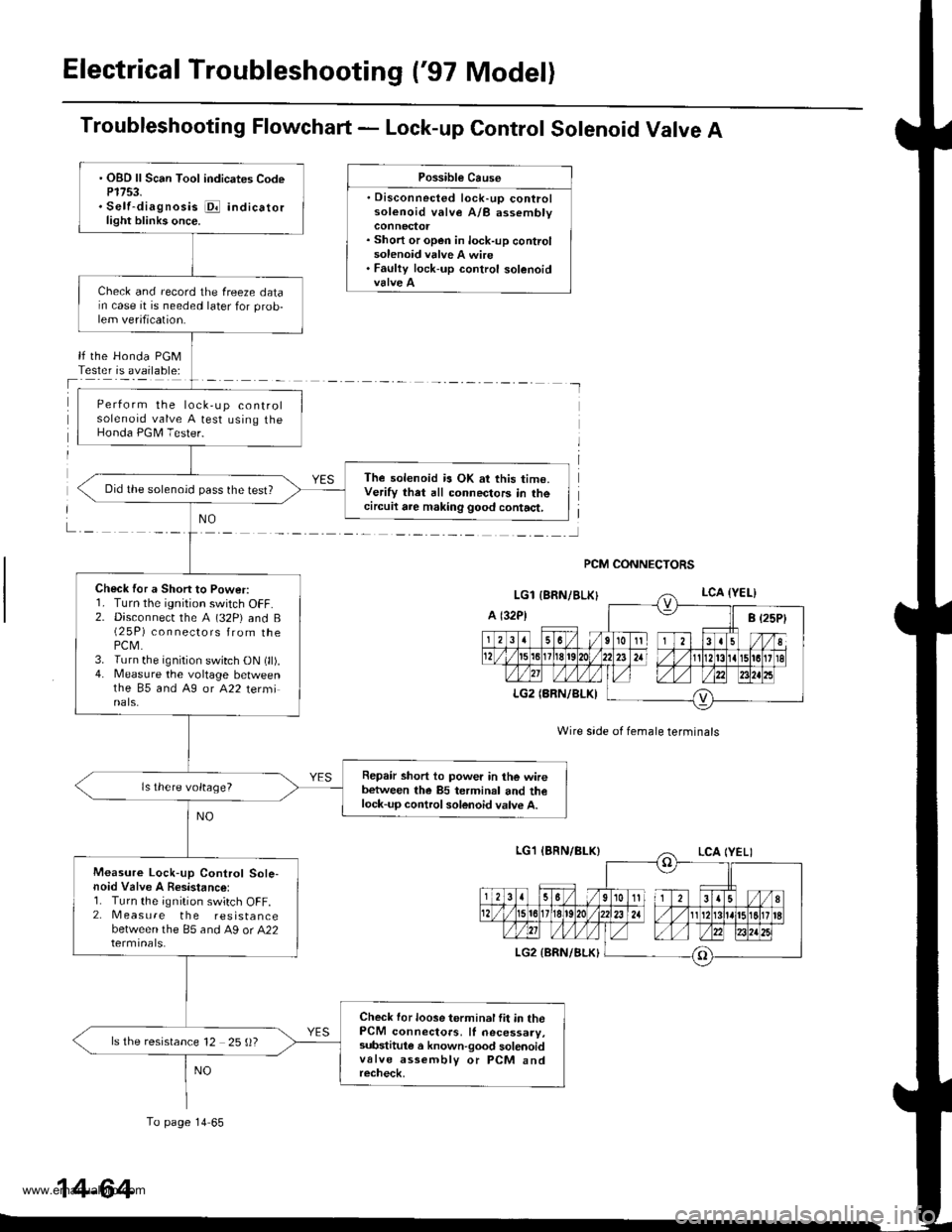
Troubleshooting Flowchart - Lock-up Control Solenoid Valve A
Possible Cause
. Disconnected lock-up controlsolenoid valve A/B assembly
. Short or open in lock-up controlsolenoid valve A wire. Faulty lock-up control solenoid
lf the Honda PGMTester is available:
NO
Wire side of female terminals
PCM CONNECTORS
. OBD ll Scan Tool indicates CodeP1753.. Self-diagnosis i@ indicatorlight blinks once.
Check and record the freeze datarn case it is needed later for prob-lem verification.
Perform the lock,up controlsolenoid valve A test using theHonda PGM Tester.
The solenoid is OK at this time.Verify that all connectors in thecircuil are making good contact,
Did the solenoid pass the test?
Check for a Short to Power:r. I urn rne tgntUon swttch ut-f.2. Disconnecr the A (32P) and B(2 5P) connectors from thePCM.3. Turn the ignition switch ON (ll).4. Measure the voltage betweenthe 85 and A9 or A22 terminals.
Repair short to power in the wirebetween the 85 terminal and thelock-up control solenoid valve A.
ls there voltage?
Measure Lock-up Control Sole-noid Valve A Resistance:1. Turn the ignition switch OFF.2. Measure the resistancebetween the 85 and A9 or A22
Check for loose terminal fit in thePCM connectors, ll necessary,substitule a known-good solenoidvalve assembly or PCM andrecheck,
ls the resistance 12 25 ()?
To page 14 65
14-64
www.emanualpro.com
Page 582 of 1395
Electrical Troubleshooting ('97 Model)
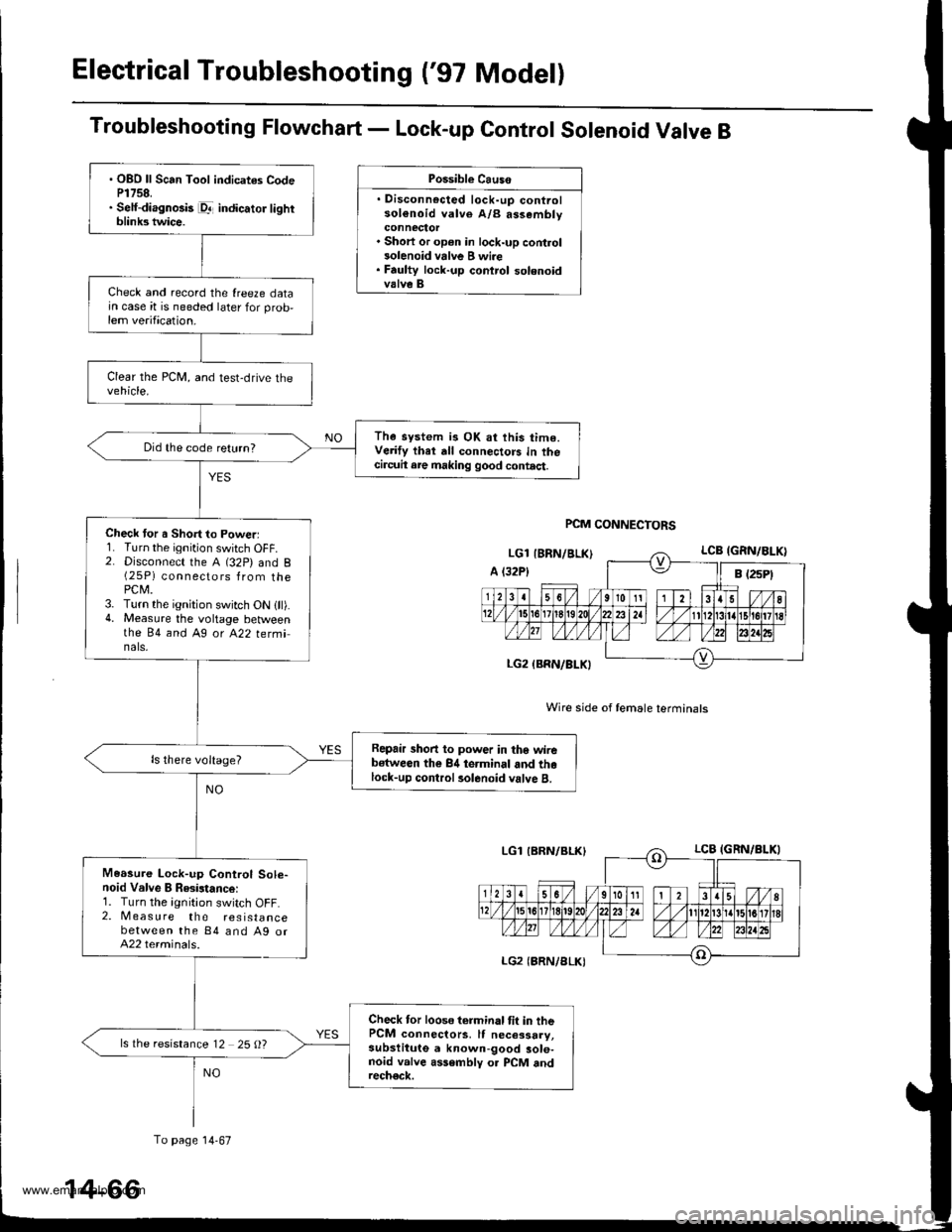
Troubleshooting Flowchart - Lock-up Control Solenoid Valve B
Possible Causo
. Disconnocted lock-up controlsol€noid valve A/B assembly
. Short or op€n in lock-up control3olenoid vrlve B wi.e. Faulty lock-up control solenoidvalve B
Wire side of female terminals
PCM CONNECTORS
. OBO ll Scan Tool indicates CodeP1758.. Self-diagnosis pr- indicator lightblink3 twice.
Check and record the {reeze datajn case it is needed later for prob,lem verification.
The system is OK at this time.Verify thet dll connectors in thecircuit are making good contact.
Did the code return?
Check tor a Short to Powerl1. Turn the ignition switch OFF.2. Disconnect the A (32P) and B(25P) connectors from thePCM.3. Turn the ignition switch ON {ll).4. Measure the voltage betweenthe 84 and Ag ot A22 tetminals,
Repair short to power in tho wirebstween the 84 terminal and thelock-up control rolenoid valve B.
Measure Lock-up Control Sole-noid Valve B Resistance:1. Turn the ignition switch OFF.2. Measure the resistancebetween the 84 and Ag orA22 terminals.
Check tor loose terminal tit in thePCM connectors, It necessary,subslitute a known-good sole-noid valve assembly o. PCM andrech€ck.
ls the resistance 12 25 O?
To page 14-67
14-66
www.emanualpro.com
Page 583 of 1395
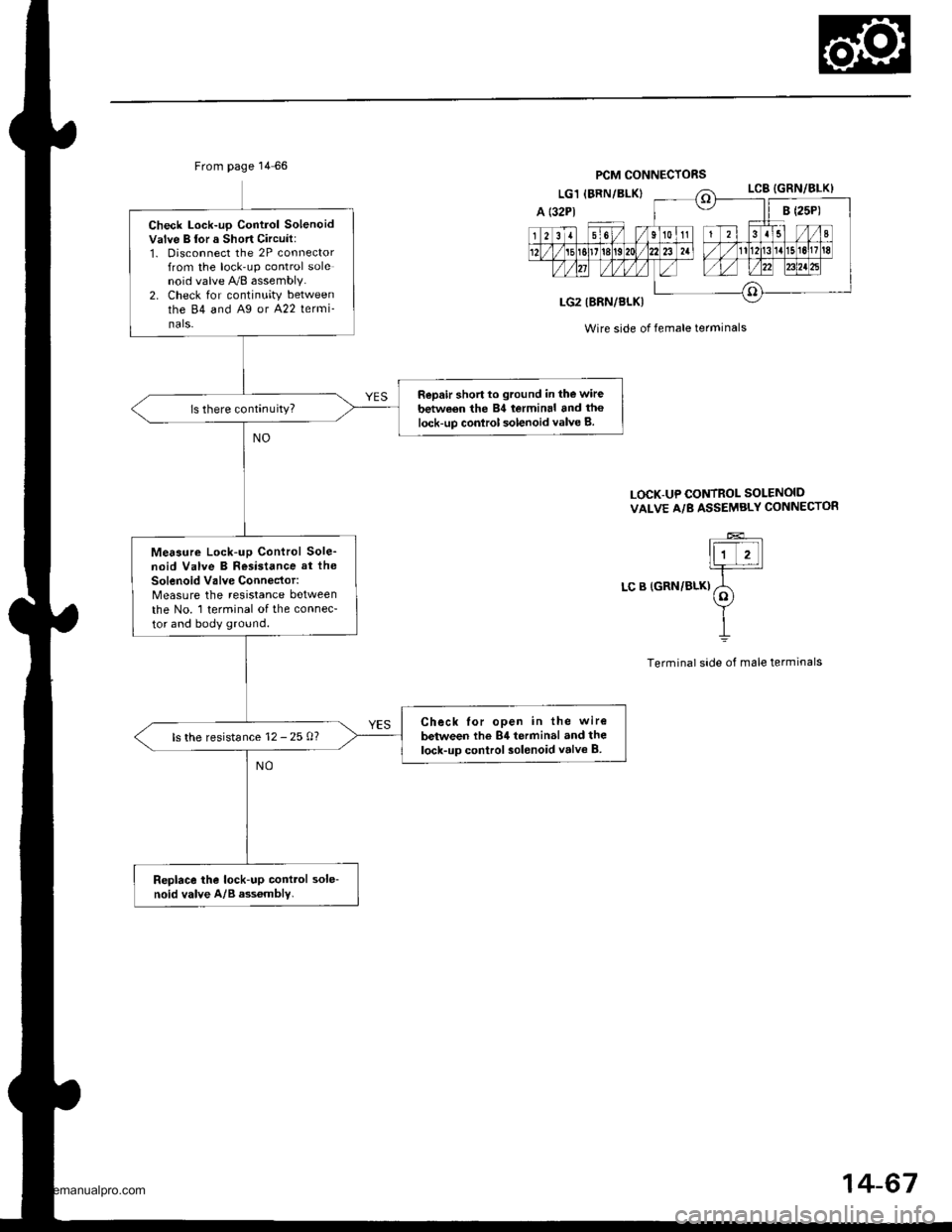
Check Lock-up Control SolenoidValve B lor a Short Circuit:1. Disconnect the 2P connectorfrom the lock-up control solenoid valve A/8 assembly.2. Check for continuity betweenthe 84 and A9 or A22 lermi_nals-
Repair short to ground in the wirebetween the 84 lerminal and the
lock-up conlrol solenoid valve B.
Me6aure Lock-up Control Sole_noid Valve B Resistance at the
Solenoid Valve Connector:Measure the resistance betweenthe No. 1 terminal of the connec-
tor and body ground.
Check lor open in the wire
bctween the 84 terminal and thelock-up control solenoid volva B.ls the resistance 12 - 25 0?
Replace the lock-up conttol sole-noid valve A/B ass6mbly.
From page 14 66PCM CONNECTORS
Wire side of female terminals
LOCK-UP CONTROL SOLENOID
VAI-VE A/B ASSEMBLY CONNECTOR
LC B (GRN/BLK)
14-67
www.emanualpro.com
Page 588 of 1395

Electrical Troubleshooting ('97 Model)
Troubleshooting Flowchart - Shift Control Solenoid Valve A
. Disconnected shift control solenoidvalve A/8 a$embly connector. Short or open in shift control sole-noid valve A wire
Possible Causo
shift control solenoid valve A
lf the Honda PGMTester is available:
I
PCM CONNECTORS
Wire side of female termin6ls
. OBD ll Scan Tool indicates CodeP0753.. Self-diagnosk E indicator lightblinks seven tim€s.
Check and record the freeze datain case it is needed later for problem verification.
Perform the shift control solenoidvalve A test using the HondaPGM Tester.
The sol€noid is OK at this time.Verify that all connectors in thecircuit are making good contact.
Did the solenoid pass the test?
Check tor a Short to Power:1. Turn the ignition switch OFF.2. Disconnect the A (32P) and B(2 5P) connectors from thePCM.3. Turn the ignition switch ON lll).4. Measure the voltage betweenthe 83 and Ag or A22 terminals.
Repair short to power in the wirebetween the 83 terminal and theshift control solenoid valve A.
Measure Shift Control SolenoidValve A Resistanco:1. Turn the ignition switch OFF.2, Measure the resistancebetween the 83 and A9 or A22termrnals,
Check tor loose terminal tit in thePCM connectors, lf necessaay,subslituie e known-good sole-noid valve assemblv or PCM andrech€ck.
ls the resistance 12 25 {)?
To page l4-73
14-72
www.emanualpro.com
Page 591 of 1395

From page 14-74
Check Shift Control SolenoidValvo B tor a Short Circuil:1. Disconnect the 2P connectorfrom the shift control solenoidvalve y'y'8 assembly.2. Check for continuity betweenthe 811 and Ag or A22 termi-nals,
Ropair short to ground in the wireb64w€€n tho 811 torminal and lhgshift control solenoid valvo B.
Meesure Shift Control SolenoidValve B Rosistance at lh€ Sole-noid Vrlve Connector:Measure the resistance betweenthe No. 2 terminal ol the connector and body ground.
Check tor open in the wirebdtweon the 811 torminal and theshift control sol€noid valv6 B.ls the resistance 12 - 25 O?
Reolace the shift control solenoidvalve A/B asJembly,
PCM CONNECTORS
Wire side of female terminals
SHIFT CONTROL SOLENOIDVALVE A/B ASSEi'BLY CONNECTOR
ti;Tll
I sH B |GRN/W{T|
o
YII
Terminal side of male terminals
14-75
www.emanualpro.com
Page 598 of 1395
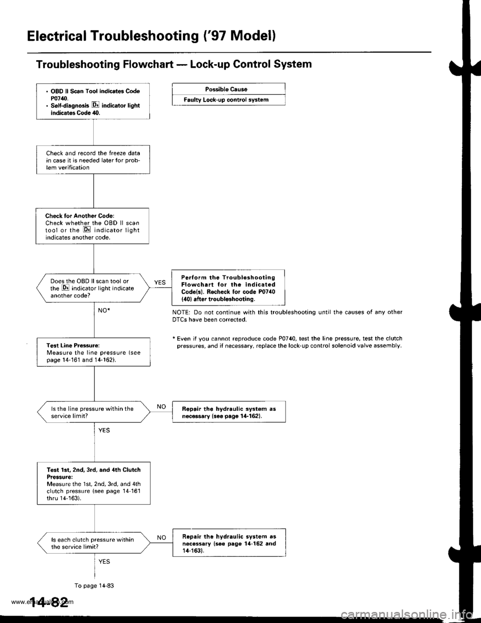
Electrical Troubleshooting ('97 Model)
. OBD ll Scan Tool indicrt6 Cod6P0740.. Self-diagno3b E indicator lightindicatos Codc 40.
Check and record the freeze datain case it is needed laterlor prob-
lem verification
Check tor Another Code:Check whether the OBD ll scantool or the E indicator lightindicates another code.
Perlorm the TroubleshootingFlowchart lor th€ indicat€dCodo{s). Rocheck tor code P0740
{ilol after troubl$hooting.
Does the OBD ll scan tool orthe E indicator light indicateanother code?
Tesl Line Pressure:Measure the line pressure (seepage 14-161 and 14-162).
ls the line pressure within theservice limit?R6pair tho hydraulic ayst€m asnecessary {see page 14-162}.
Test lst, 2nd, 3rd, and 4th ClutchPressure:Measure the 1st, 2nd, 3rd, and 4thclutch pressure (see page 14161thru 14''163).
Repair the hydraulic system dsnecessary {see pago 14-152 rnd14-163).
ls each clutch pressure withinthe service limit?
Troubleshooting Flowchart - Lock-up Control System
Possiblo Cause
Faulty Lock-up control sy3t6m
NOTE: Do not continue with this troubleshooting until the causes of any otherDTCS have been corrected.
* Even if yotl cannot reproduce code P0740. test the line pressure, test the clutchpressures, and i{ necessary, replace the lock-up control solenoid valve assembly
1
To page 14-83
4-82
www.emanualpro.com