Page 352 of 1395

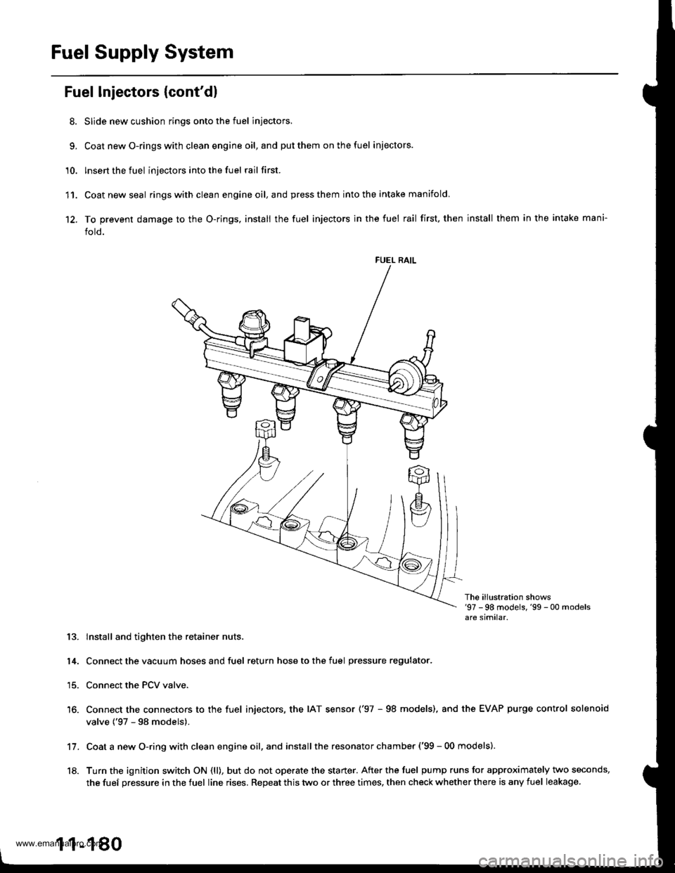
ldle Control System
ldle Control System
I P0505 | The scan tool indicates Diagnostic T.ouble Code (DTCI PO5O5: ldlecontrol svstem mattunction.
NOTE: lf DTC P1508 is stored at the same time as DTC P0505, troubleshoot DTC P1508 first. then troubleshoot DTC p0505.
Possibls Cause
. IAC valve mechanical malfunction. Throttle body clogged port, improper adlustment. Intake manifold gasket leakaging. Intake air hose loose leakaging. Vacuum hose leakaging
a ECT sensor incorrect output. Throttle Position sensor incorrect output
Troubleshooting Flowchart
The MIL has been reDorted on.DTC P0505 is sto.ed.
Problem verificationi1. Start the engine. Hold theengine at 3,000 rpm with noload (in Park or neutral) untilthe radiator Ian comes on, thenlet it idle.2. With the scan tool, check thelollowing items.- Throttle position should beapprox. 10% with the throt-tle {ully closed.- Engine coolant temperature shorJld be 194 - 205'F(90 - 96"C).lf they are not within thespec., repair the faulty sen-sor circuit.3 Check the engine speed atidle with no-load conditions:headlights, blower fan. reardefogger, radiator lan, and airconditioner are not operaling,
Inte.mittent failure. syltem is OKat this time.ls it 750 {730)* i 50 rpm?
ls il 700 (680)' rpm or less?
{To page 11-151)(To page 1'l-151)
l:'99 - 00 models
www.emanualpro.com
Page 381 of 1395
Fuel Injectors
R6placomoni
1. Relieve the fuel pressure (see page 11-178).
2. Remove the resonato. chamber ('99 - 00 models).
O.RINGBeplace.
Disconnect the connectors from the fuel injectors, and disconnect the IAT sensor 2P connector ('97 - 98 models) and
EVAP purge control solenoid valve 2P conn€ctor ('97 - 98 models),
Disconnect the PCV valve and the vacuum hose from the fuel pressure regulator.
Place a shop towel over the fuel return hose, then disconnect it from the fuel pressure regulator.
Remove the retainer nuts on the fuel rail.
Disconnect the fuel rail.
7, Remove the fuel injectors from the intake manifold.
'97 - 98 model3:
EVAP PURGE CONTROLSOLENOID VALVE 2P CONNECTORIAT SENSOR
FUEL PULSATION2P CONNECTOR
12 N.m{1.2 kgt'm,8.7 tbtft)
FUELPRESSUREREGULATOR
O.RING
FUELPRESSUREREGULATOR
CUSHION
O.RINGReplace.
CUSHIONRINGReplace.
SEALRINGReplace.
Replace.
SEALRINGReplace.
S
11-179
www.emanualpro.com
Page 382 of 1395

Fuel Supply System
Fuel Injectors {cont'dl
8. Slide new cushion rings onto the fuel injectors.
9, Coat newO-ringswith clean engine oil,and putthem onthefuel iniectors.
'10. lnsert the fuel injectors into the fuel rail first.
11. Coatnewseal ringswithclean engineoil,and press them into the intake manifold
12. To prevent damage to the O-rings, install the fuel injectors in the fuel rail first, then install them in the intake mani-
fold.
FUEL RAIL
The ill!stration shows'97 -98 models,'99 - 00 modelsare similar.
13. lnstall and tighten the retainer nuts.
14. Connect the vacuum hoses and fuel return hose to the fuel pressure regulator.
15. Connect the PCV valve.
16. Connect the connectors to the fuel injectors, the IAT sensor ('97 - 98 models), and the EVAP purge control solenoid
valve {'97 - 98 models).
Coat a new O-ring with clean engine oil, and install the resonator chamber ('99 - 00 models).
Turn the ignition switch ON (ll), but do not operate the starter. After the fuel pump runs for approximately two seconds,
the fuef pressure in the fuel line rises. Repeat this two or three times, then check whether there is any fuel leakage.
11.
18.
1 1-180
www.emanualpro.com
Page 402 of 1395

Emission Control System
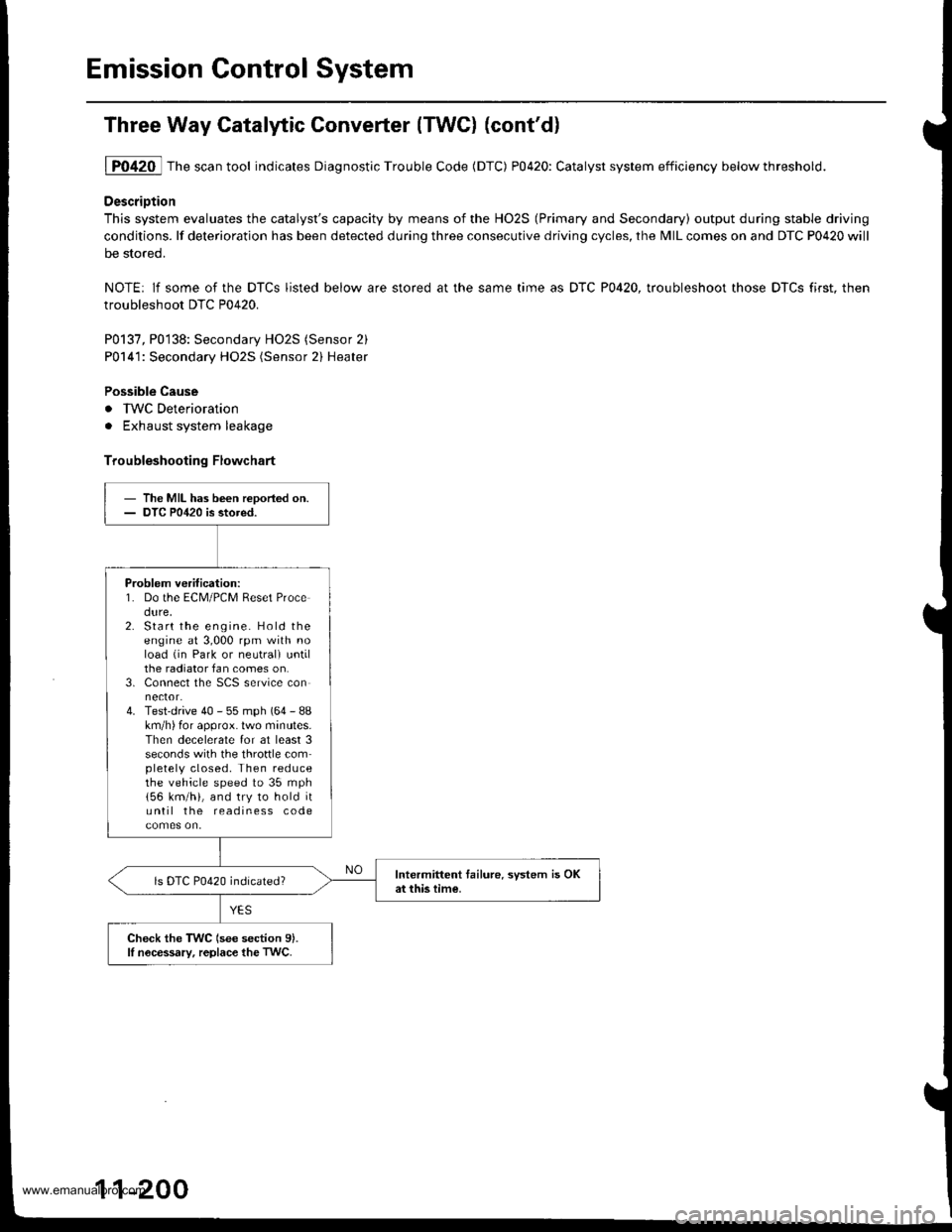
Three Way Catalytic Converter {TWCI (cont'd}
1P0420 Thescantool indicates Diagnostic Trouble Code (DTC) P0420: Catalyst system efficiency belowthreshold.
DescriDtion
This system evaluates the catalyst's capacity by means of the HO2S (Primary and Secondary) output during stable driving
conditions. lf deterioration has been detected during three consecutive driving cycles, the MIL comes on and DTC P0420 will
be stored.
NOTE: lf some of the DTCS listed below are stored at the same time as DTC P0420, troubleshoot those DTCS first. then
troubleshoot DTC P0420.
P0137, P0138: Secondary HO2S (Sensor 2)
P0141: Secondary HO2S (Sensor 2) Heater
Possible Cause
. IWC Deterioration
. Exhaust system leakage
Troubleshooting Flowchart
- The MIL has been reDoried on.- DTC P0420 is stored.
Problem verification:1. Do the ECM/PCM Reset Procedure,2. Start the engine. Hold theengine at 3,000 rpm with noload (in Park or neutrali untilthe radiator fan comes on.3. Connect the SCS service connector.4. Test-drive 40 - 55 mph (64 - 88km/h) for approx. lwo minutes.Then decelerate for at least 3seconds with the throftle completely closed. Then reducethe vehicle speed to 35 mph
156 km/h), and try to hold ituntil the readiness code
Intermittent tailure. system is OKat this time.ls DTC P0420 indicated?
Check the TWC (see section 9).lI nocessary, replace the TwC.
11-200
www.emanualpro.com
Page 407 of 1395

'97 model:
The scan tool indicates Diagnostic Trouble Code (DTC) P0441: Evaporative Emission (EVAP) control system
insufficient purge flow.
Description
By monitoring the purge line vacuum with the MAP sensor, the PCM can detect insufficient EVAP control system purge
flow.
Possiblo Cause
. EVAP Purge Control Solenoid Valve
. EVAP Purge Control Solenoid Valve Circuit
. EVAP Control Canister
. Vacuum Lines
. PCM
Troubleshooting Flowchart
EVAP PURGE CONTROL
SO1TNOID VALVE 2P
CoNNECTOR (C108)
(v)
YL
Wire side of female
termrnals
(cont'd)
11-205
Th€ MIL has b€en reooited on.DTC P0441 is .tored.
Problem verificationl1. Start the engine. Hold theengine at 3,000 rpm with noload (in Park or neut.al) untilthe radiator fan comes on.2. Do the PCM Reset Procedure.3. Connect the SCS service con-nector,4. Test drive under following con'ditions on the road.- without any electrical load- Transmission in @ or @position- Engine speed between1 ,2OO - 2,4OO rpfi.- Decelerate from 50 mph (80
km/h)to 15 mph (24 km/h)Intermittent trilure, sydern is OKat this time. Check for Door con-nections or loose wir€3 at C108
IEVAP purge control solonoidvalvol .nd at the PCM.
ls DTC P0441 indicated?
Check tor an open in the wire (lcl
linel:1. Turn the ignition switch OFF.2. Disconnect the EVAP purge
control solenoid valve 2P con-nector.3. Turn the ignition switch ON (ll).
4. Measure voltage between bodyground and the EVAP purge
control solenoid valve 2P con-nector terminal No. '1,
R€pafu open in thc wir6 b€tw€enthG EVAP purge control solenoidvalve and the No. 15 ALTEBNA-TOR SP SENSOR (7.5 A)fuse.
ls there batlery voltage?
(To page 11'206)
www.emanualpro.com
Page 445 of 1395

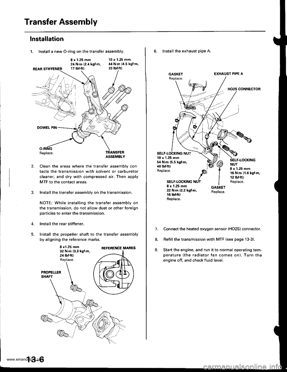
Transfer Assembly
lnstallation
1. Install a new O-ring on the transfer assembly.
8 x 1.25 mm24 N.m (2.4 kgt m,17 rbt.ftl
10 x 1.25 mm44 N.m (4.5 kgJ.m,
2.
DOWEL PIN
Replace.TRANSFEBASSEMBLY
Clean the areas where the transfer assembly con
tacts the transmission with solvent or carburetor
cleaner, and dry with compressed air. Then apply
MTF to the contact areas.
Installthe transfer assembly on the transmission.
NOTE: While installing the transfer assembly on
the transmission, do not allow dust or other foreign
particles to enter the transmission.
lnstall the rear stiffener.
Install the propeller shaft to the transfer assembly
by aligning the reference marks,
8 x1.25 mm32 N.m 13.3 kg{.m,24 tbf.ftl
REFERENCE MARKS
6. Install the exhaust pipe A,
GASKETEXHAUST PIPE A
HO2S CONNECTOR
10 x 1 .25 mm54 N.m (5.5 kgt m,40 tbtfttReplace.
SELF.LOCKING
NUT8 x 1.25 mm16 N.m {1.6 kgf.m,12 tbt.ft)Replace.8 x 1.25 mmzzN.m l2.2kg!-m,16 rbf.trtReplace.
7.Connect the heated oxygen sensor (HO2S) connector.
Relill the transmission with MTF (see page 13-3).
Start the engine, and run it to normal operating tem-
perature (the radiator tan comes on). Turn the
engine off. and check fluid level.
8.
9.
www.emanualpro.com
Page 448 of 1395
12. Disconnect the heated oxygen sensor (HO2S) con-
nector, then remove the exhaust pipe A.
GASKETReplace.
HO2S CONNECTOR
NUTReplace.
EXHAUST
SELF.LOCKINGReplace.
GASKETReplace.
Mark reference marks on the joint of the transfer
and the propeller shaft.
8 x 1.25 mmReplace.
Separate the propeller shaft from the transfer
assemDly.
REFERENCE MABKS
14.
15. Remove the cotter pins, and castle nuts. then sepa-
rate the ball ioints from the lower arm (see sectlon
18).
OAMPER PINCH BOLT
CASTLE NUTNUTReplace.
17.
16.
DAMPER FORKFOFKEOLTReplace.
Remove the right damper tork bolt, then separate
right damper fork and damPer.
Pry the right driveshaft out of the differential, and
pry the left driveshaft out of the intermediate shaft
(see section 18).
Pull out the inboard ioint, and remove the right and
left driveshaft (see section 18).
Tie plastic bags over the driveshatt ends. Coat all
precision finished surfaces with clean engine oil
18.
19.
\
{cont'd}
13-9
www.emanualpro.com
Page 673 of 1395

Road Test
NOTE: Warm up the engine to normal operating temperature (the radiator tan comes on).
1. Before testing, check the transmission fluid level, see page 14-160.
2. Apply the parking brake and block the wheels. start the engine, then shift to E {'97 - 98) or E {'gg - 00) position
while pressing the brake pedal. Press the accelerator pedal and release it suddenly. The engine should not stall.
3. Repeat same test in E position ('97 - 98 models).
4. Test-drive the vehicle on a flat road in the E or E position. Check that the shift points occur at approximate speeds
shown on a flat road. Also check for abnormal noise and clutch slippage.
Throttle position sensor voltage represents the throttle opening. Monitor it with the Honda PGM Tester or as follows:
a. Unbolt the PCM for road testing; reJer to page 14-58.
b. Set the digital multimeter to check throttle position sensor voltage between these terminals on the PCM:
. '97 Model: Between terminals D'! (+) and A9 (-) or A22 {-}
. '98 - OO Models; Between terminals C27 (+) and 820 (-) or 822 {-)
BACKPROBE ADAPTER
BACKPROBE SETorsAz - 001moA(two roquircdl
STACKING PATCH
CORD
DIGiTAL MULTIMETER
{Comm€rcirllY .vailablc}KS-AHM-32-003,or equival.nt
'97 Model:PCM CONNECTORS
'98 - 0O Models:
A l32Pt
Wire side of female terminals
PCM CONNECTORS
B {25Pt c l31P}
(cont'd)
LGl (BRN/BLK)
'. //B 1 l'o ti , jl. to a 2r / / 11111t1.t nait la t1 t213tr / t6t, tl / / / / 1 3 / 10n v
t-'a:IM-&E -Llfiffi-fl)\"".'E
Wire side ot female termanals14-157
www.emanualpro.com