Page 493 of 1395

Transfer Assembly
Reassembly (cont'd)
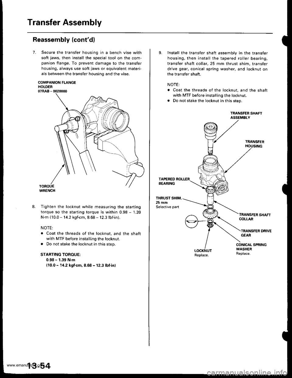
7.Secure the transfer housing in a bench vise with
soft jaws, then install the special tool on the com-
panion flange. To prevent damage to the transfer
housing, always use soft jaws or equivalent materi-
als between the transfer housing and the vise.
COMPANION FLANGEHOLDER07RAB - 0020000
WRENCH
8. Tighten the locknut while measuring the starting
torque so the starting torque is within 0.98 - 1.39
N.m {10.0 - 14.2 kgf.cm. 8.68 - 12.3 lbf.in).
NOTE:
. Coat the threads of the locknut, and the shaft
with MTF before installing the locknut.
. Do not stake the locknut in this step.
STARTING TOROUE:
0.98 - 1.39 N.m(10.0 - 14.2 kgf.cm, 8.68 - 12.3 lbf.in)
9.Install the transfer shaft assembly in the transfer
housing, then install the tapered roller bearing,
transfer shaft collar,25 mm thrust shim, transfer
drive gear, conical spring washer, and locknut on
the transfer shaft.
NOTE:
. Coat the threads of the locknut, and the shaft
with MTF before installing the locknut.
. Do not stake the locknut in this step.
TRANSFER SHAFTASSEMBLY
TRANSFER
THRUST SHIM.25 mmSelective part
COLLAR
TRANSFER DRIVEGEAR
CONICAL SPRINGWASHERReplace.Replace.
www.emanualpro.com
Page 495 of 1395

Transfer Assembly
Reassembly (cont'dl
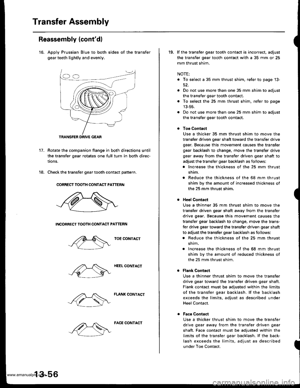
16. Apply Prussian Blue to both sides of the transfer
gear teeth lightly and evenly.
Rotate the companion flange in both directions until
the transfer gear rotates one full turn in both direc-
tions.
Check the transfer gear tooth contact pattern.
CORREST TOOTH CONTACT PATTERN
INCORRECT IOOTH CONTACT PATTERN
TOE CONTACT
HEEL CONTACT
FLANK CONTACT
17.
18.
TRANSFER DRIVE GEAR
13-56
FACE CONTACT
19. lf the transfer gear tooth contact is incorrect, adjust
the transfer gear tooth contact with a 35 mm or 25
mm thrust shim.
NOTE:
. To select a 35 mm thrust shim, refer to page '13-
. Do not use more than one 35 mm shim to adjust
the transfer gear tooth contact.
. To select the 25 mm thrust shim, refer to page
13-55.
a Do not use more than one 25 mm shim to adjust
the transfer gear tooth contact.
Toe Contact
Use a thicker 35 mm thrust shim to move the
transfer driven gear shaft toward the transfer drive
gear. Because this movement causes the transfer
gear backlash to change, move the transfer drive
gear away from the transfer driven gear shaft to
adjust the transfer gear backlash as iollows;
. Increase the thickness of the 25 mm thrust
shim.
. Reduce the thickness of the 68 mm thrust
shim bv the amount of increased thickness of
the 25 mm thrust shim.
Heol Contact
Use a thinner 35 mm thrust shim to move the
transfer driven gear shaft away from the transfer
drive gear. Because this movement causes the
transfer gear backlash to change, move the trans-
fer drive gear toward the transfer driven gear shaft
to adjust the transfer gear backlash as follows:
. Reduce the thickness of the 25 mm thrust
sh im.
a Increase the thickness of the 68 mm thrust
shim by the amount of reduced thickness of
the 25 mm thrust shim.
Flank Contact
Use a thinner thrust shim to move the transfer
drive gear toward the transfer driven gear shaft.
Flank contact must be adtusted within the limits
of the transfer gear backlash. lf the backlash
exceeds the limits, adjust as described under
Heel Contact.
Face Contsct
Use a thicker thrust shim to move the transfer
drive gear away from the transfer driven gear
shaft. Face contact must be adjusted within the
limits of the transjer gear backlash. lf the back-
lash exceeds the limits, adjust as described
under Toe Contact.
www.emanualpro.com
Page 496 of 1395

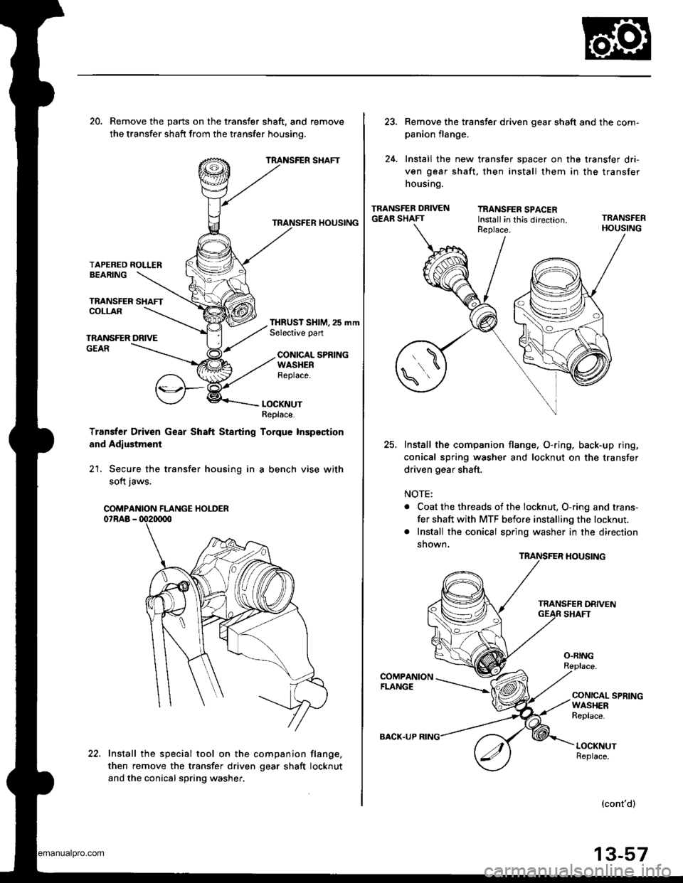
20. Remove the parts on the transfer shaft, and remove
the transfer shatt from the transfer housinq.
TRANSFER SHAFT
TRANSFER HOUSING
TAPERED ROLLERBEARING
TRANSFER SHAFTCOLLAR
TMNSFER DRIVEGEAR
THRUST SHIM, 25 mmSelective part
CONICAL SPRINGWASHERReplace.
LOCKNUTReplace.
Transter Driven Gear Shaft Starting Torque Inspection
and Adlustment
21. Secure the transfer housing in a bench vise with
soft iaws.
Install the special tool on the companion flang€,
then remove the transfer driven gear shaft locknut
and the conical spring washer.
COMPANION FLANGE HOLDER
22.
BACK.UP
Remove the transter driven gear shaft and the com-
panion flange.
Install the new transfer spacer on the transfer dri-
ven gear shaft, then install them in the transfer
housing.
TRANSFER DRIVENGEAR SHAFTTRANSFER SPACERInstall in this direction.TRANSFER
25.Install the companion flange, O-ring, back-up ring,
conical spring washer and locknut on the transfer
driven gear shaft.
NOTE:
. Coat the threads of the locknut, O-ring and trans-
fer shaft with MTF before installing the locknut.
. Install the conical spring washer in the direction
shown.
TRANSFER HOUSING
O.RING
COMPANIONFLANGECONICAL SPRINGWASHERReplace.
LOCKNUTReplace.
(cont'd)
13-57
www.emanualpro.com
Page 497 of 1395

Transfer Assembly
Reassembly (cont'dl
26. Secure the transfer housing in a bench vise with
soft jaws.
COMPANION FLANGE HOLDER07RAB - 002tD00
27. Install the special tool on the companion flange.
then tighten the transfer driven gear shaft locknut
while measuring the starting torque of the transfer
driven gear shaft.
STARTING TOROUE:
0.98 - 1.39 N.m
{10.0 - 1i1.2 kgf.cm, 8.68 - 12.3 lbf in}
TIGHTENING TOROUE:
132 - 216 N.m
(13.5 - 22.0 kgf.m, 97.6 - 159 lbf.ft)
NOTE:
. Rotate the companion flange several times to
seat the tapered roller bearing, then measure the
startrng torque.
. lf the starting torque exceeds 1.39 N.m (14.2
kgf.cm, 12.3 lbf.in), .eplace the transfer spacer
and reassemble the parts. Do not adjust the
torque with the locknut loose.
. lf the tightening torque exceeds 216 N.m (22.0
kgf.m, 159 lbf'ft), replace the transfer spacer and
reassemble the parts.
. Write down the measurement of the starting
torque: it is used to measure the total starting
torque.
28. Stake the locknut into the transfer driven oear shaft
using a 3.5 mm punch.
0.7 - 1.2 mm(0.03 - 0.05 inl
Point to bestaked.
Install the transfer shaft assemblv in the transfer
housing, then install the tapered roller bearing,
transfer shaft collar, 25 mm thrust shim, transfer
drive gear, conical spring washer, and transfer shaft
locknut on the transfer shaft.
NOTE:
. Coat the threads of the locknut and transfer shaft
with MTF before installing the locknut.
. lnstall the conical spring washer in the direction
snown.
TMNSFER SHAFTASSEMBLY
TRANSFER HOUSING
TAPERED ROLLERBEARING
TRANSFER SHAFTCOLLAR
TRANSFER DRIVEGEAR
PUNCH3.0-3.5 mm10.12 - 0.1a inl
THRUST SHIM, 25 mmSelective part
CONICAL SPRINGWASHEBReplace.
LOCKNUTReplace.
29.
www.emanualpro.com
Page 498 of 1395
30. Hold the transfer shaft with a 14 mm Allen wrench
clamDed in a bench vise.
NOTE: The locknut has left-hand threads.
TOROUE: 118 N.m (12.0 kgt'm,86.8 lbf'ft)
31. Stake the locknut on the transfer shaft using a 3.5
mm Dunch.
PUNCH3.0 - 3.5 mm{0.12 - 0.14 inl
14 mm ALLEN WRENCH
Totsl Starting Torquo Inspoction and Adiustment
32. Temoorarilv install transfer cover A without the O-
ring.
TRANSFER HOUSING
TRANSFER COVER A
oEl
€lE/Ehvc/E\\g8 x 1 .25 mm24 N.m (2.4 kg{ m, 17 lbtftl
5t.Secure the transfer housing in a bench vise with
soft jaws. then rotate the companion flange several
times to fit the tapered roller bearing,
TOROUE WR€NCH
34. Measure the total starting torque.
TOTAL STARNNG TOROUE:
1.70 - 2.08 N.m 117.3 - 21.2 kgf.cm, 15.0 - 18.i1 lbf inl
+ Transter Driven Gear Shaft Starting Torque Value
(wrot€ down in step 27).
(cont'd)
13-59
www.emanualpro.com
Page 501 of 1395
Mainshaft Bearing/Oil Seal
Replacement
1. Remove the ball bearing using the specialtool.
3/8" -16 SLIDE HAMMER(Commercially available)
PULLER.25 - ,10 mm07736 - A01000A
2. Remove the oil seal from the clutch housing.
13-62
BALL BEARING
3. Drive the new oil seal in from the transmission side
using the special tools.
ATTACHMENT,12x 17 .nfi07746 - 0010300
Drive the new bali bearing in from the transmission
side using the special tools.
ATTACHMENT.62x68mm07746 - 0010500
www.emanualpro.com
Page 502 of 1395
Gountershaft Bearing
Replacement
1. Remove the retaining plate from the clutch housing.
CLUTCH HOUSING
HETAINING PLATE
Remove the needle bearing using the special tool,
then remove the oil guide plate.
Replace.
3/8" -16 SLIDE HAMMER(Commercially available)
CLUTCH TIOUSING
^'ADJUSTABI.f BEARINGPULLER,25 - 40 mm07736 - A01(x)04
NEEDLE BEARING
Position the oil guide plate.
Drive the needle bearing using the special tools.
ATTACHMENT,62x88mm07746- 0t!105q)
NEEDII AEARING
Install the retaining plate, and stake the bolt heads
into the groove in the retaining plate
6x1.0mm12 N.m (1.2 kgt m,8.7 lbtftl
13-63
www.emanualpro.com
Page 512 of 1395
8. Installthe right front mounvbracket.
12 x 1 .25 mm64 N.m (6.5 kgf'm,47 tbf.ftlReplace.
RIGHT FRONTMOUNT/BBACKET
10 x 1.25 mm4,a N.m (4.5 kgf m,
33 tbf ftl
Install the clutch housing cover and rear engine
stiffener.
6xl0mm12 N.m 11.2 kgt.m.8.7 tbf.ft)
HOUSING
'12 x 1.25 mm29 N.m 13.0 kgf.m. 22 lbf'ft)
8 x 1.25 mm24 N.m {2.5 kgf'm'
18 tbl.ft)
10 x 'l .25 mm44 N.m {4.5 kgf m,33 lbf ftl
10. Pour transmission fluid of 1 liter from the driveshaft
inserted hole.
1 1. lnstall the intermediate shaft {see section 18). While
installing the intermediate shaft in the differential.
be sure not to allow dust and other foreign particles
to enter the transmission.
10 r 1.25 mm39 ttm 14.0 kgf.m,29 tbt ftlSET RINGReplace.
12. lnstall the driveshafts (see section 18). While
installing the driveshaft(s) in the differential, be sure
not to allow dust and other foreign panicles to enter
the transmission.
SET RINGReplace.
(cont'd)
13-73
INTERMEOIATE SHAFT
DRIVESHAFT
www.emanualpro.com