Page 888 of 1395
20. Press the new bearing into the valve housing with
the stamped letter facing up using a hydraulic press
and soecialtool.
ATTACHMENT,32x35mm07746 - 0010100
- ROLLER BEARINGLetter stamped face
21. Apply vinyl tape to the pinion shaft, then coat the
vinyltape with power steering fluid.
Sealing lip tace.VALVE OIL SEAL
VALVE HOUSING
SHAFT
SLEEVE SEAL
PINION
E
22, Insert the pinion shaft into the valve housing. Be
careful not to damage the valve seal rings.
23. Remove the vinyl tape from the pinion shaft, then
remove any residue from the tape adhesive.
8e sure that theseal rings are notturned up, theninstall.
DRIVER
24. Press the pinion shaft/sleeve using a hydraulic
press. Check that the pinion shaft/sleeve turns
smoothly by turning the pinion shaft,
(cont'd)
17-43
www.emanualpro.com
Page 910 of 1395

Front Suspension
Knuckle/Hub Replacement (cont'd)
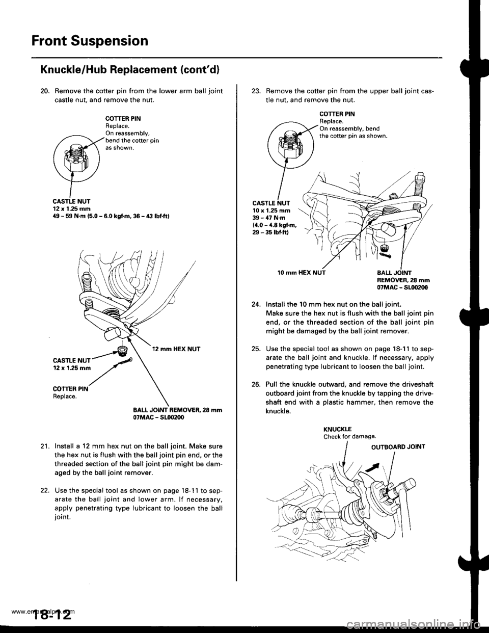
20. Remove the cotter pin from the lower arm ball joint
castle nut, and remove the nut.
COTTER PINReplace.On ra6ssembly,bend the cofter pin
CASTI.E NUT12 x 1.25 mmilg - 59 N.m (5.0 - 6.0 kgf.m, 36 - a3 lbf.ftl
CASTLE NUT12 x 1.25 mm
COITER PINReplace.
BALL JOINT REMOVER, 28 mm07MAC - Sl(xr2(x,
Install a 12 mm hex nut on the ball joint. Make sure
the hex nut is flush with the ball joint pin end, or the
threaded section of the ball joint pin might be dam-
aged by the ball joint remover.
Use the special tool as shown on page 18-11 to sep-
arate the ball joint and lower arm. lf necessary,
apply penetrating type lubricant to loosen the balljoint.
18-12
23. Remove the cotter pin from the upper ball joint cas-
tle nut, and remove the nut.
COTTER PINReplace.On reassembly, bendthe cotter pin as shown.
CASTLE NUT10 x 1.25 mm39 - 47 N.m14.0 - ,4.8 kgt m,29 - 35 tbt.ftl
24.
25.
26.
10 mmnEMOVER, 28 mm07MAC _ SLtD2(xl
Install the 10 mm hex nut on the ball joint.
Make sure the hex nut is flush with the ball joint pin
end, or the threaded section of the ball joint pin
might be damaged by the ball joint remover.
Use the special tool as shown on page 18-11 to sep-
arate the ball joint and knuckle. lf necessary, apply
penetrating type lubricant to loosen the ball joint.
Pull the knuckle outward, and remove the driveshaft
outboard joint from the knuckle by tapping the driv+
shaft end with a pl8stic hammer, then remove the
knuckle.
KNUCKI.ECheck lor damage.
www.emanualpro.com
Page 912 of 1395

Front Suspension
31.
Knuckle/Hub Replacement (cont'dl
Wash the knuckle and hub thoroughly in high flash
point solvent before reassembly,
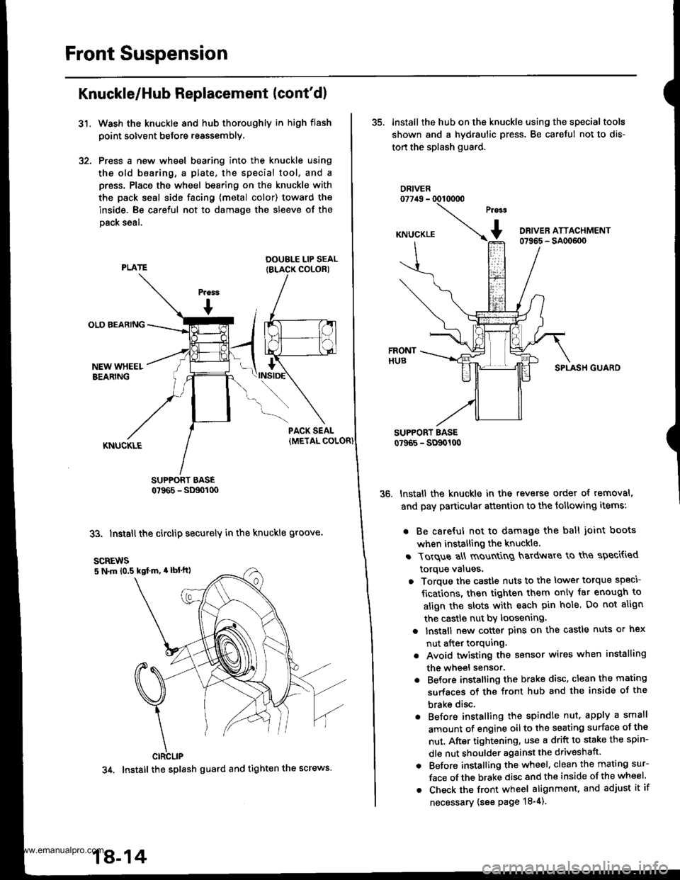
Press a new wheel bearing into the knuckle using
the old b6aring, a plate. the special tool, and a
press. Place the wheel bearing on the knuckle with
the pack seal side facing (metal color) toward the
inside. Be careful not to damage the sleeve of the
Dack seal.
DOUBLE LIP SEALIBLACK COLORI
SUPPORT BASE0?965 - SD90t00
33. Install the circlip securely in the knuckle groove.
35. lnstall the hub on the knuckle using the specialtools
shown and a hydraulic press. Be careful not to dis-
tort the splash guard.
ORIVER077irg - 0010000
SPLASH GUARO
lnstall the knuckle in the reverse order of removal,
and pay particular attention to the following items:
. Be careful not to damage the ball joint boots
when installing the knuckle.
r Torque a\ mount
g hardv{are to ths speci{ied
torque values,
o Torque the castle nuts to the lower torque speci
fications, then tighten them only iat enough to
align the slots with each pin hole. Do not align
the castle nut by loosening.
a lnstall new cotter pins on the castle nuts or hex
nut after torquing.
. Avoid twisting the sensor wires when installing
the wheel sensor.
. Before installing the brake disc, clean the mating
surfaces of the front hub and the inside of the
brake disc.
. Before installing the spindle nut, apply a small
amount of engine oil to the seating surface oJ the
nut. After tightening, use a drift to stake the spin-
dle nut shoulder against the driveshaft.
. Before installing the wheel. clean the mating sur-
face of the brake disc and the inside of the wheel.
. Check the front wheel alignment, and adjust it if
necessary {see page 18-4).
scREws5 N.m 10.5 kgl m, 4 lbl'tt)
CIRCLIP
34. Install the splash guard and tight€n the screws.
18-14
www.emanualpro.com
Page 916 of 1395

Front Damper
Reassembly
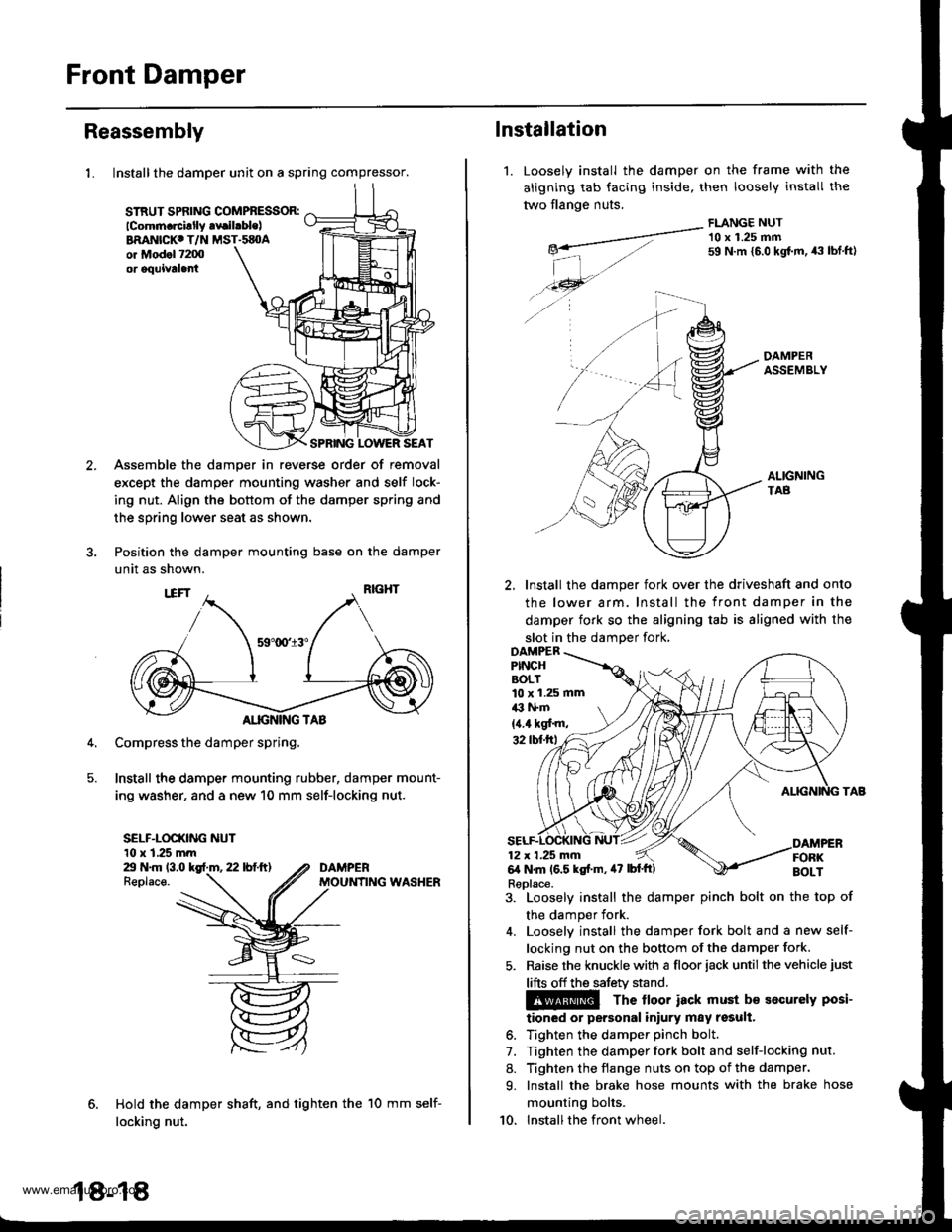
1. Install the damper unit on a spring compressor.
STRUT SPflNG COMPBESSOR:lcomm.rcillly .vrilrble)BRANICKC T/N MST.sEOAor Mod.l 7200or oquivtla
SPRING LOWER SEAT
Assemble the damper in reverse order of removal
except the damper mounting washer and self lock-
ing nut. Align the bottom of the damper spring and
the spring lower seat as shown.
Position the damper mounting base on the damper
unit as shown.
Compress the damper spring,
Install the damper mounting rubber, damper mount-
ing washer, and a new 10 mm self-locking nut.
SELF-LOCKING NUT10 x 1.25 mmZt N.m 13.0 kgf.m, 22 lbf.ft)Replace.
Hold the damper shaft, and tighten the
locking nut.
DAMPERMOUNfING WASHER
18-18
10 mm self-
1.
lnstallation
Loosely install the
aligning tab facing
two flange nuts.
damper on the frame with
inside, then loosely install
FLANGE NUT
the
tne
-__---a-"- 10 x 1.25 mmg*- 59 N.m {5.0 kgt m, 43 tbf.ftl
| -,./.46- --...
./ -4 A-
DAMPERASSEMBLY
ALIGNINGTAB
2, Install the damper fork over the driveshaft and onto
the lower arm. Install the front damper in the
damper fork so the aligning tab is aligned with the
slot in the damDer fork,
3. Loosely install the damper pinch bolt on the top of
the damper fork.
4. Looselv install the damper fork bolt and a new self-
locking nut on the bottom of the damper fork.
5. Raise the knuckle with a floor iack until the vehicle just
lifts off the safetv stand.
The lloor iack must b€ socurely posi-
tioned or personal iniury may result.
6. Tighten the damper pinch bolt.
7. Tighten the damper fork bolt and self-locking nut.
8. Tighten the flange nuts on top of the damper.
9. Install the brake hose mounts with the brake hose
mounting bolts.
10. Installthe front wheel.
10 x 1.25 mmil3 l+m
{4.4 kgf'm,
Replace.
www.emanualpro.com
Page 920 of 1395

Rear Suspension
Hub Bearing Unit Replacement (cont'd)
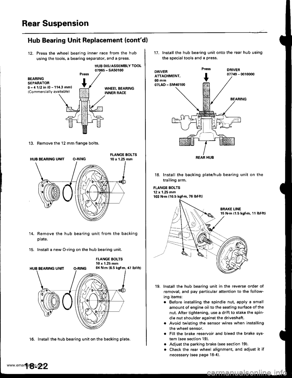
12, Press the wheel bearing inner race from the hub
using the tools, a bearing separator, and a press.
HUB DIS/ASSEMBLY TOOL07965 - SA50100
BEARINGSEPARATOR0 -,t 1/2 in {0 - 11i1.3 mml(Commercially qvailable)
13. Remove the 12 mm flange bolts.
HUB BEARING UN]T O.RING
14. Remove the hub bearing unit from the backing
plate.
15. Install a new O-ring on the hub bearing unit.
FLANGE BOLTS10 x 1.25 mm64 N.m (6.5 kgf.m, 47 lbf.ftl
16. Install the hub bearing unit on the backing plate.
18-22
't7.Install the hub bearing unit onto the rear hub using
the special tools and a press.
DRIVERATTACHMENT,60 mm07LAO - SM40100
Prcss
+
DRIVER07749 - 0010000
BEARING
18. Install the backing plate/hub
trailing arm.
FLANGE BOLTS12 x 1.25 mm103 N.m 110.5 kgf'm,75lbfft)
bearing unit on the
19. Install the hub bearing unit in the reverse order of
removal, and pay particular attention to the follow-
ing items:
. Before installing the spindle nut, apply a small
amount of engine oil to the seating surface of the
nut, After tightening, use a drift to stake the spin-
dle nut shoulder against the driveshaft.
. Avoid twisting the sensor wires when installing
the wheel sensor,
. Fill the brake reservoir and bleed the brake sys-
tem {see section 19).
. Adjust the parking brake (see section 191.
. Check the rear wheel alignment, and adjust it if
necessary (see page 18-4).
REAR HUB
www.emanualpro.com