Page 368 of 1395
ldle Control System
Brake Switch Signal
This signals the ECM/PCM when the brake pedal is depressed.
('97 model)'- - - - -_- Il
PCM CONNECTORSa t32P) D ll6Pl
BKSW(GRN/WHT)
Wire side of female terminals
Insp€ction of Brak. Switch Signal.
Are the brake lights on withoutpressing the brake pedal?
Inspect the HORN, STOP {15 A)fuse in the undeFhood luse/ relaybox.Do the brake lights come on?
Reoair short in the wire be-tween th€ b.ake switch andth6 HoRN, STOP {15 A)luso,Replaco the HoRN, STOP (15
Al fuse.
Repair op6n in the wir€ be-tween the brake switch andtho HORN, STOP (15 Allus6.Inspect the brrke switch (see
aection l9l.
Check tol .n open in the wire{BXSW linel:1. Press the brake pedal.2. Measure voltage between rcMconnector terminais D5 and Agwith the brake pedal pressed.
Reprir open in the wire betweenthe PcM lD5l rnd the brakeswitch.
(To page 11-167)
1 1-166
www.emanualpro.com
Page 390 of 1395
![HONDA CR-V 2000 RD1-RD3 / 1.G Workshop Manual
Fuel Supply System
PGM-FI Main Relay (contdl
Troubleshooting
lc(}21PGM.FI MAIN RELAY 7P CONNECTOR
GND
trTr]--Flq
FI,TilI A
Y
Wire side ot female terminals
- Engine will not start.- InsDection ol PG HONDA CR-V 2000 RD1-RD3 / 1.G Workshop Manual
Fuel Supply System
PGM-FI Main Relay (contdl
Troubleshooting
lc(}21PGM.FI MAIN RELAY 7P CONNECTOR
GND
trTr]--Flq
FI,TilI A
Y
Wire side ot female terminals
- Engine will not start.- InsDection ol PG](/manual-img/13/5778/w960_5778-389.png)
Fuel Supply System
PGM-FI Main Relay (cont'dl
Troubleshooting
lc(}21PGM.FI MAIN RELAY 7P CONNECTOR
GND
trTr]--Flq
FI,Til'I A
Y
Wire side ot female terminals
- Engine will not start.- InsDection ol PGM-FI mainrelay and relay harness,
Check fo. an open in the wireIGND linol:1. Turn the ignition switch OFF.2. Disconnect the PGM Fl mainrelay 7P connector.3. Check for continuity betweenthe PGM'FI main relay 7P con-nector terminal No. 3 and bodyground.
Repair opcn in th€ wire betweenthe PGM-FI main relav and G101.
Check tor an open or short in thewiro (BAT line):Measure voltage between thePGM'FI main relay 7P connectorterminal No. 7 and body ground.- Repai. open or short in lhewir6 belween the PGM-FImain relay and the Fl E/M (15Al fu3e.- Replace th6 FIE/M (15 Altus6in th€ under-hood fuse/.6lay
ls there baftery voltage?
Check lor an open or short in thewire (lGl line):L Turn the ignition switch ON (ll).2. Measure the voltage betweenthe PGM-FI main relay 7P connectorterminal No. 5 and bodyground.- Repair open or shorl in thewire between the FGM-FI mainrelay and the No. 13 FUELPUMP 115 A) tuse.- Replaco the No. 13 RJEL PUMP115 A) luse in the und6.-d$hfuso/ relav box.Check for an open or short in thewire {STS line):1. Turn the ignition switch to theSTART (lll) position.NOTE:. M/T: Clutch pedal must bedepressed.. A/T: Transmission in E orElposition.2. Measure the voltage betweenthe PGM-Fl main retay 7Pconnector terminal No. 2 andbody ground.- Repair open or short in thewire betwe€n the PIGM-FI m.inrclay and th€ No. 31 STARTERSlGllAL 17.5 A) tuse.- Repl.ce the No. 31 STARTERSIGNAL 17.5 Al tuse in theunder-dash tuse/relay box.('97 model: To page 11-189)('98 00models:To page 1l 190)
1 1-188
www.emanualpro.com
Page 411 of 1395

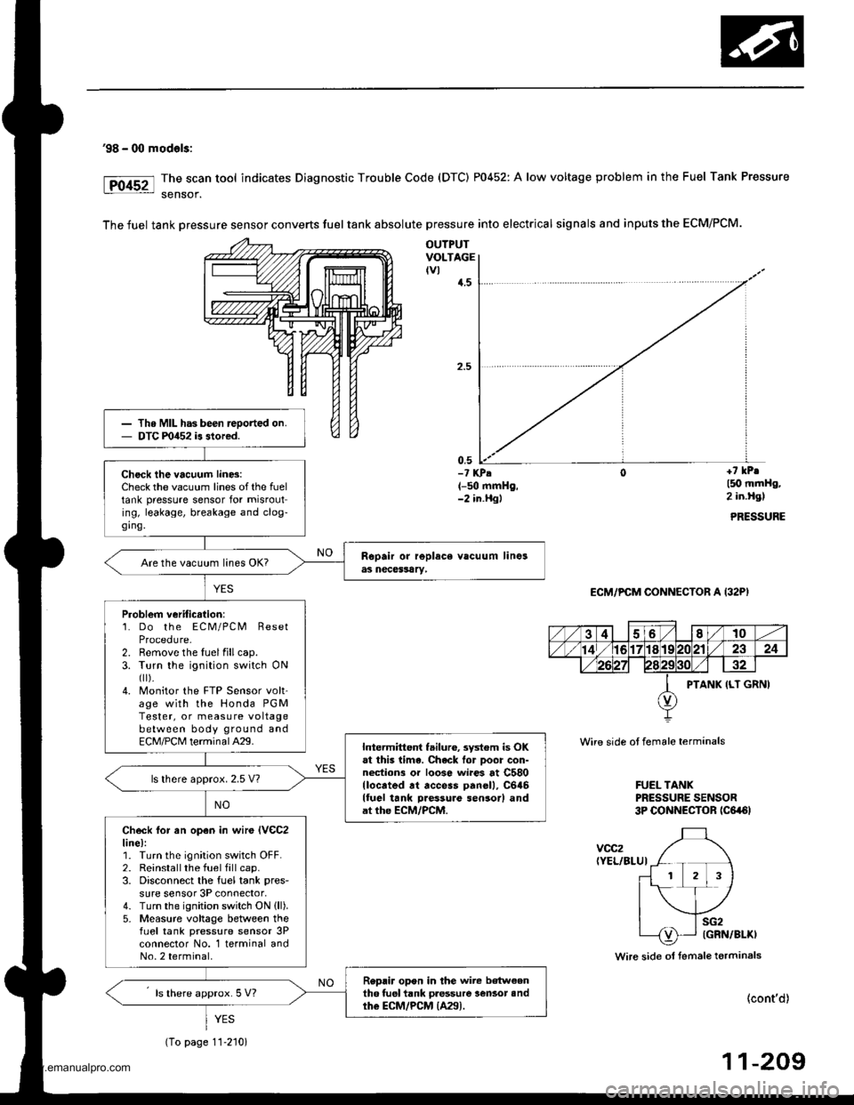
'98 - 00 mod€ls:
The scan tool indicates Diagnostic Trouble Code (DTC) P0452: A low voltage problem in the Fuel Tank Pressure
sensof.
The fuel tank Dressure sensor converts fuel tank absolute pressure into electrical signals and inputs the ECM/PCM.
OUTPUTVOLTAGEtvl{.5
0,5-? KPA(-50 mmHg,-2 in.Hgl
+7 kPr
l5O mmHg,2 in.Hgl
PRESSURE
ECM/PCM CONNECTOR A (32P)
Wire side ot female terminals
FUEL TANKPRESSURE SENSOR3P CONNECTOR tc6a6l
voc2(YEL/BLUI
Wire side ol fsmale terminals
(cont'd)
11-209
Th. MIL has been reoorted on.DTC m452 is stored.
Check the vacuum lin6:Check the vacuum lines of the fueltank pressure sensor for misrouting, leakage, breakage and clog-ging.
Are the vacuum lines OK?
Problem veriticstion:1. Do the ECM/PCM ResetProcedure-2. Remove the luelfillcap.3. Turn the ignition switch ONfl r).4. Monitor the FTP Sensor volt'age with the Honda PGMTester, or measure voltagebetween body ground andECM/PCM terminalA29.Intermittent failuro, system is OKat this lima. Chack lor Door con-nections or loose wi.es at C580llocrted rt access panell, C646lluel tank Daessure sensor) andat the ECM/PCM.
ls lhere approx. 2.5 V?
Check lor an open in wir€ lVeC2line):1. Turn the ignition switch OFF.2. Reinstallthe fuel fill cap.3. Disconnect the fuel tank pres-
sure sensor 3P connector,4. Turn the ignition switch ON (ll).
5- Measure voltage between thefLrel tank pressure sensor 3Pconnector No. 1 terminal andNo.2 terminal.
Replir opon in the wire b€tw€enth6 tuel tank pressure lensot andthe ECM/PCM {A29).ls there approx. 5 V?
YES
(To page 11-210)
www.emanualpro.com
Page 531 of 1395
Electronic Control System
The electronic control svstem consists of a Powertrain Control Module (PCM), sensors, a linear solenoid, and four solenoid
valves. Shifting and lock-up are electronically controlled for comfortable driving under all conditions. The PCM is located
below the dashboard, under the kick panel on the passenger's side.
'97 - 98 Mod€ls
PGM.FIControl Sy3t6m
Throttl€ Poshion SensorSignalVehicle Sp.ed SensorSignal
Engino Coolant TamperetureService Check connectorSonsor Signrl
A/T Control Sy3tem
INTERLOCK
Shift Cont.ol
Shift ControlSolenoid valve ACONTROL UNITr
RShift ControlSolenoid Valve B
N
Linear SolenoidDr
Lock-up Control
Ds
Lock-up ControlSolenoid Valve A2
Lock-up ConirolSol6noid valvo B1
M.inshaft Spoed SensorSignel-D! Indicator Light
Count€rahaft Speedsensor SignelSelt-Oiagnosb signel
I
Sell-DiagnosisFunction
l-
{cont'd)
14-15
www.emanualpro.com
Page 532 of 1395
Description
PCM
PGM.FIControl System
Throttle Position SensorSignelVehicle Speed SensorSignal
Engin€ Coolsnt TomperatureSen30r SignalService Ch€ck Connectol
A/T Control Svstem
INTERLOCK
Shift Control
Shift ConlrolSolenoid Valve ACONTROL UNITr
RShift ControlSolenoid Valve B
N
Linear SolenoidD
Lock-up Control
2
Lock-up ControlSolenoid valve A1
Lock-up ControlSolenoid Valve BOver-DriveSwitch Signal
Mainshaft Speed SensorSignalE Indicator Light
Countershaft SpeedSensor SigntlSelt-Oiagnosis SigndSelf-DiagnosisFunc{ion
O/D OFFIndicetor Light
Electronic Gontrol System (cont'd)
'99 - 00 Models
14-16
www.emanualpro.com
Page 533 of 1395

Shift Control
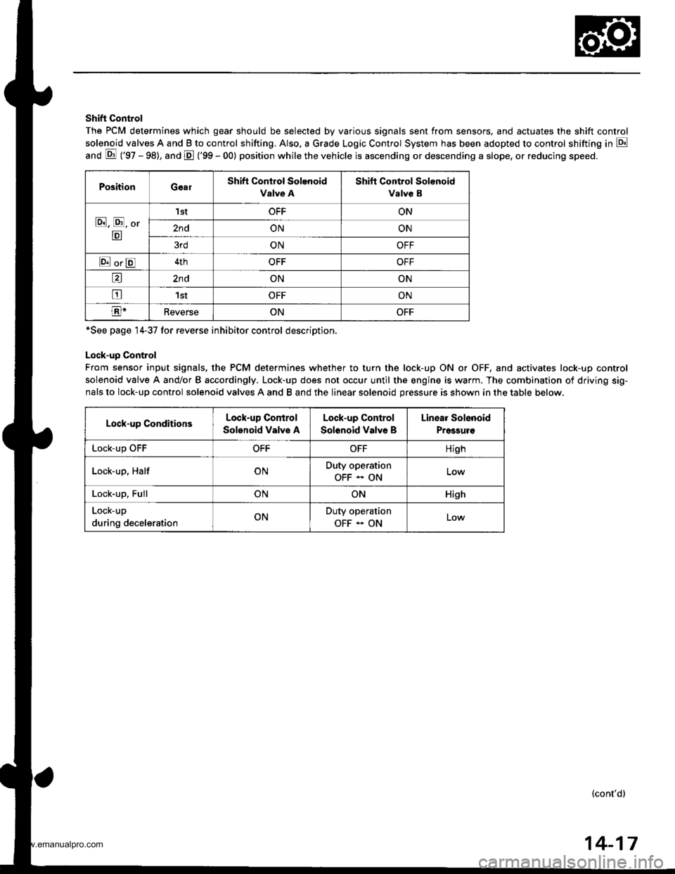
The PCM determines which gear should be selected by various signals sent from sensors, and actuates the shift control
solenoid valves A and B to control shifting. Also. a Grade Logic Control System has been adopted to control shifting in E
anO E ('gZ - gg), and E ('99 - 00) position while the vehicle is ascending or descending a slope, or reducing speeo.
PositionGearShift Control Solenoid
Valve A
Shift Control Solonoid
Valve B
E, E, Or
E
'I stOFFON
2ndONON
3rdONOFF
E orE4thOFFOFF
a2ndONON
tr1stOFFON
E-ReverseONOFF
*See page 14-37 for reverse inhibitor control description.
Lock-up Control
From sensor input signals, the PCM determines whether to turn the lock-up ON or OFF, and activates lock-up control
solenoid valve A and/or B accordingly. Lock-up does not occur until the engine is warm. The combination of driving sig-
nals to lock-up control solenoid valves A and B and the linear solenoid pressure is shown in the table below.
Lock-up ConditionsLock-up Control
Solonoid Valve A
Lock-up Control
Solenoid Valve B
Linear Solenoid
Pressuro
LOCK-Up \JrrOFFOFFHigh
Lock-up, HalfONDuty operation
OFF - ON
Lock-up, FullONONHish
Lock-up
during decelerationONDuty operation
OFF - ONLow
(cont'd)
14-17
www.emanualpro.com
Page 534 of 1395
Description
Electronic Control System (cont'dl
Grade Logic Control System
How it works:
The PCM compares actual driving conditions with memorized driving conditions, based on the input from the vehicle speed
sensor, the throttle position sensor, the barometric pressure sensor ('98 model). the engine coolant temperature sensor, the
brake switch signal, and the shift lever position signal, to control shifting while the vehicle is ascending or descending a
slope, or reducing speed.
SIGNALS DETECTED
Driving Rcsisl.nce
Judgemont ot Controlling Aroa
. Normal Modo {Flrt ro.d mode}. Ascending Mode. Deacending Mode. Deceleration Mode
14-14
www.emanualpro.com
Page 553 of 1395

E Position
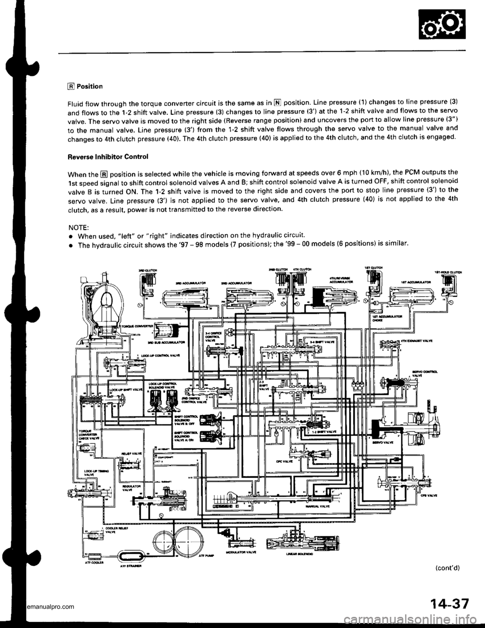
Fluid flow through the torque converter circuit is the same as in N position. Line pressure (1) changes to line pressure (3)
and flows to the 1-2 shift valve. Line pressure (3) changes to line pressure (3') at the 1-2 shift valve and flows to the servo
vaive. The servo valve is moved to the right side (Reverse range position) and uncovers the port to allow line pressure (3")
to the manual valve. Line pressure (3') from the 1-2 shift valve flows through the servo valve to the manual valve and
changes to 4th clutch pressure (40). The 4th clutch pressure (40) is applied to the 4th clutch, and the 4th clutch is engaged.
R€verse Inhibitor Control
When the @ position is selected while the vehicle is moving forward at speeds over 6 mph (10 km/h), the PCM outputs the
1st speed signal to shift control solenoid valves A and B; shift control solenoid valve A is turned OFF, shift control solenoid
valve B is turned ON. The 1-2 shift valve is moved to the right side and covers the port to stop line pressure (3') to the
servo valve. Line pressure {3') is not applied to the servo valve, and 4th clutch pressure (40} is not applied to the 4th
clutch, as a result, power is not transmitted to the reverse direction.
NOTE:
. When used, "lelt" ot " right" indicates direction on the hydraulic circuit.
. The hvdraulic circuit shows the '97 - 98 models (7 positions); the '99 - 00 models (6 positions) is similar'
(cont'd)
14-37
www.emanualpro.com