2000 HONDA CR-V honda pgm
[x] Cancel search: honda pgmPage 588 of 1395

Electrical Troubleshooting ('97 Model)
Troubleshooting Flowchart - Shift Control Solenoid Valve A
. Disconnected shift control solenoidvalve A/8 a$embly connector. Short or open in shift control sole-noid valve A wire
Possible Causo
shift control solenoid valve A
lf the Honda PGMTester is available:
I
PCM CONNECTORS
Wire side of female termin6ls
. OBD ll Scan Tool indicates CodeP0753.. Self-diagnosk E indicator lightblinks seven tim€s.
Check and record the freeze datain case it is needed later for problem verification.
Perform the shift control solenoidvalve A test using the HondaPGM Tester.
The sol€noid is OK at this time.Verify that all connectors in thecircuit are making good contact.
Did the solenoid pass the test?
Check tor a Short to Power:1. Turn the ignition switch OFF.2. Disconnect the A (32P) and B(2 5P) connectors from thePCM.3. Turn the ignition switch ON lll).4. Measure the voltage betweenthe 83 and Ag or A22 terminals.
Repair short to power in the wirebetween the 83 terminal and theshift control solenoid valve A.
Measure Shift Control SolenoidValve A Resistanco:1. Turn the ignition switch OFF.2, Measure the resistancebetween the 83 and A9 or A22termrnals,
Check tor loose terminal tit in thePCM connectors, lf necessaay,subslituie e known-good sole-noid valve assemblv or PCM andrech€ck.
ls the resistance 12 25 {)?
To page l4-73
14-72
www.emanualpro.com
Page 590 of 1395

Electrical Troubleshooting ('97 Model)
Troubleshooting Flowchart - Shift Control Solenoid Valve B
Po33ibla Crusa
. Disconnec{ed shift cont.ol solenoidvalve A/B dssombly connector. Short or open in shift conlrol sole-noid valvg B wire' Faultv shift comrol 3olenoid valvo B
lf the Honda PGMT€ster is available:
PCM CONNECTORS
Wire side ot female terminals
. OBO ll Scan Toot indicrt8 CodoP0758.. Setf-diagnGis E indicator lightblinks oight tim93.
Check and r€cord the lreere datain case it is needed later for prob
lem verilication.
Test solenoid valve B with theHonda PGM Tester in the FLrnction test mode.
The 3olonoid is OK at this time.Verifv that all connoctors in thecircuit are making good contlct.Did the solenoid Dass the test?
Chock tor a Sho.t to Power:1. Turn the ignition switch OFF.2. Disconnect the A (32P) and B{25P) connectors Irom the PCM.3. Turn the ignition switch ON (ll).
4. Measuro the voltage botveenthe 811 and Ag or A22 termi-nats.
R.p.ir 3hort to power in the wirebotwo€n the 811 iormin.l andtho shift control sol.noid valve B.
M.6sure Shift Control SolonoidValve B Reaistanco:1. Turn the ignition switch OFF.2. Measure the r€sistancebetween the 811 and A9 orA22 terminals.
Checl lor loosc terminal fil in thePCM connactors. It nocessarv,substitute a known-good aole-noid vllvo asssmbly or PCM andr6chsck,
ls the resistance 12 - 25 O?
To page 14-75
14-74
www.emanualpro.com
Page 592 of 1395

Electrical Troubleshooting ('97 Model)
Troubleshooting Flowchart - Countershaft Speed Sensor
Possible Cause
. Loose or faulty connection betweenih€ PCM and vehicle harness. Disconnected countershaft spoedsensor conneclor. Short or open in countershaft speed
. Faulty counteBhaft speed lensor
lf the Honda PGMTester is available:I
J
COUNTERSHAFT SPEED SENSOR
CONNECTOR
ll-'T,ll-rT
ral
YIL__l
Terminal side of male terminals
. OBO ll Scan Tool indicates Codem720.' solt-diagnosis iD!' indicator lightblink3 nine tim6s.
Check and record the freeze datain case it is needed later for problem verification.
Connect the Honda PGM Tester,and test-drive the vehicle withthe tester in Data Link or snap'Shot mode, Make sure the coun-tershaft speed sensor reads thesame as the vehicle speed sensorlVSS).
The countershaft sooed sensor isOK sr this time. Veritv that allconnecloas in the circuit aremaking good contacl.
Check the countershaft speedsensor installation, and check itfor damage.
ls the countershaft speed sen-sor installed properly, and notdamaged?neinstall or roDlaco and recheck.
Measuro CountoBhaft Speed Sen-sor Relbtance at the Sensor Con-nector:1. Disconnect the 2P connectorfrom the countershaft speedsensor connector.2. Measure the resistance of thecountershaft speed sensor.
ls the resistance 400 - 600 o?
To page 14-77
14-76
www.emanualpro.com
Page 594 of 1395

Electrical Troubleshooting {'97 Model)
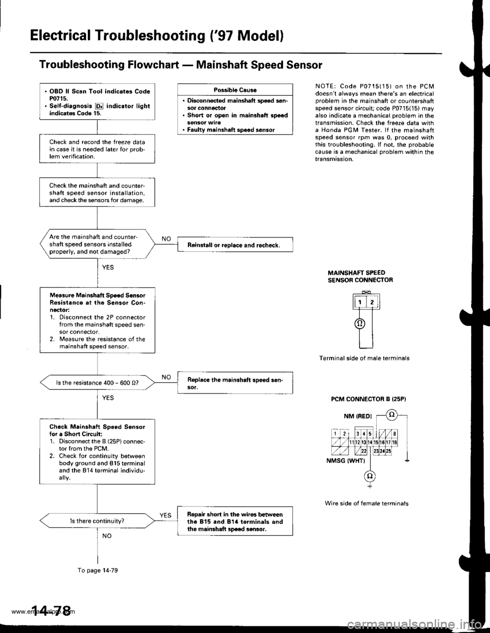
Troubleshooting Flowchart - Mainshaft Speed Sensor
Po$ible Cau3o
. Disconnocted mainshaft speod sen-sot connectot. Short or open in mainsh.ft sp6ed
' Faulty meinshaft spoed sensor
NOTE: Code P0715115) on the PCMdoesn't always mean there's an electricalproblem in the mainshaft or counlersharlspeed sensor circuit; code P0715(15) mayalso indicate a mechanical problem in thetransmission. Check the freeze data witha Honda PGM Tester. lf the mainshaftspeed sensor rpm was 0, proceed withthis troubleshooting. lf not, the probablecause is a mechanical problom within thetransmission,
MAINSHAFT SPEEOSENSOR CONNECTOR
_E_
ItiT,ll-F=r
9t
LJ
Terminal side of male terminals
PCM CONNECTOR B {25P'
Wire side of female terminals
. OBD ll Scan Tool indic.t6 Codem715.. Self-diagnosis E indic.tor lightindicatag Code 15.
Check and record the freeze datain case it is needed later {or prob,lem verification.
Check the mainshaft and counter-shaft speed sensor installation,and checkthe sensors for damage.
Are the mainshaft and counter-shaft speed sensors installedproperly, and not damaged?Reingtall or reolace and recheck.
Meaaure MaiNhatt Spoed Sen3orR6sist!nce at the Sensor Con-necaor:1. Disconnect the 2P connectorfrom the mainshaft speed sen-sor connector.2. lreasure the resistance of themainshaft speed sensor.
ls the resistance 400 - 600 O?
Check Mainahaft Speed Sensortor a Short Circuit:1. Disconnect the B (25P) connec-tor lrom the PCM.2. Check for continuity betlveenbody ground and 815 terminaland the 814 terminal individu-
ReDair short in the wir€6 b€t reenthe 815 and 814 torminals andthe mainsh!ft sp€ed sensor.
To page l4-79
14-78
www.emanualpro.com
Page 673 of 1395

Road Test
NOTE: Warm up the engine to normal operating temperature (the radiator tan comes on).
1. Before testing, check the transmission fluid level, see page 14-160.
2. Apply the parking brake and block the wheels. start the engine, then shift to E {'97 - 98) or E {'gg - 00) position
while pressing the brake pedal. Press the accelerator pedal and release it suddenly. The engine should not stall.
3. Repeat same test in E position ('97 - 98 models).
4. Test-drive the vehicle on a flat road in the E or E position. Check that the shift points occur at approximate speeds
shown on a flat road. Also check for abnormal noise and clutch slippage.
Throttle position sensor voltage represents the throttle opening. Monitor it with the Honda PGM Tester or as follows:
a. Unbolt the PCM for road testing; reJer to page 14-58.
b. Set the digital multimeter to check throttle position sensor voltage between these terminals on the PCM:
. '97 Model: Between terminals D'! (+) and A9 (-) or A22 {-}
. '98 - OO Models; Between terminals C27 (+) and 820 (-) or 822 {-)
BACKPROBE ADAPTER
BACKPROBE SETorsAz - 001moA(two roquircdl
STACKING PATCH
CORD
DIGiTAL MULTIMETER
{Comm€rcirllY .vailablc}KS-AHM-32-003,or equival.nt
'97 Model:PCM CONNECTORS
'98 - 0O Models:
A l32Pt
Wire side of female terminals
PCM CONNECTORS
B {25Pt c l31P}
(cont'd)
LGl (BRN/BLK)
'. //B 1 l'o ti , jl. to a 2r / / 11111t1.t nait la t1 t213tr / t6t, tl / / / / 1 3 / 10n v
t-'a:IM-&E -Llfiffi-fl)\"".'E
Wire side ot female termanals14-157
www.emanualpro.com
Page 952 of 1395

ABS Control
The ABS control unit detects the wheel speed based on the wheel sensor signal it received, then it calculates the vehicle
speed based on the detected wheel speed. The control unit detects the vehicle speed during deceleration based on the
rate of deceleration.
The ABS control unit calculates the slip rate of each wheel, and it transmits the control signal to the modulator unit
solenoid valve when the slip rate is high
The pressure reduction control has three modes: pressure reducing, pressure retaining, and pressure intensi{ying modes.
Self-diagnosis Function
The ABS control unit is equipped with a main cPU and a sub cPU, that check each other for problems.
The CPUs check the circuit of the system.
When the CPUS detect failure, they shift to the "system down mode" or the "control inhibition mode".
The self-diagnosis can be classitied into these four categories:
O: Initial diagnosis
O: Except ABS control
O; During ABS control
@: During warning
On-board Diagnosis Function
The ABS system can be diagnosed with the Honda PGM Tester.
The ALB Checker cannot be used with this system. For air bleeding. and checking wheel sensor signals, use the Honda
PGIM Tester. See the Honda PGM Tester user's manuals for specific operating instructions.
(cont'd)
19-29
ABS CONTROL I-INIT
MODEABSINDICATOR LIGHTMAIN
RE LAY
SOLENOID
VALVERestan conditionDTC
SYSTEM
DOWNONNo
operatron
Drive
inhibitionOperation*rlgnition
switchOFF - oN (ll)Memory
CONTROL
INHIBITIONONNo
operaton
Drive
inhibitionOperationAutomaticlVemory
*1: Except CPU failure
www.emanualpro.com
Page 958 of 1395

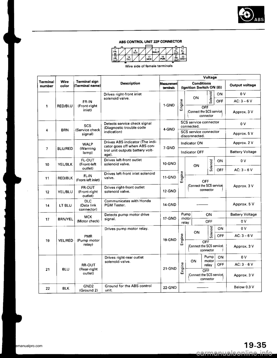
ABS CONTROL UNIT 22P CONNECIOR
Wire side ol lemale terminals
TerminalnumDerWirecolorTerminal 3i9nTerminal nameDescription
Voltage
Conditions(lgnition Switch ON (ll)lOutput voltagetominals
1RED/BLUFR-IN(Front-right
inlet)
Drives right-front inletsolenoid valve.
1-GND.9otur
ONIONOV
OFFAC:3-6V
OFF
lconnect the SCS servicel
connedor lApprox.3 V
BRN(Service checksignal)
Detects service check signal(Diagnostic trouble codeindication)4.GND
SCS service connectorconnected.OV
SCS service connectordisconnected.Approx. S V
7BLU/RED(Warning
ramp)
Drives ABS indicator {The indi-
cator goes off when ABS con-
trol unit outputs battery volt-age).
7.GND
lndicator ONApprox. 2 V
lndicator OFFBattery Voltage
10YEUBLKFL-OUT(Frontieft
outlet)
Drives left-front outletsolenoid valve.1O-GNDON
=
I
ONOV
OFFAC:3-6V
l'lRED/BLKFL-IN(Front-left inlet)
Drives left-front inlet solenoid11-GNDOFF
lconnect the SCS servicq connector lApprox.3 V
YEUBLUFR-OUT(Front-right
outlet)
Drives right-front outletsolenoid valve.12-GND
14LT BLU(Data linkconnectod
Communicates with HondaPGM Tester.14-GNDApprox. 5 V
17BRN/YELMCK(Motor check)
Detects PumP motor drivesignal.17-GNDPumpmotorrelay
ONBattery Vollage
OFFOV
19YEUREDPMR(Pump motorreray,
Drives pump motor relay.
19.GNDcl)
ON6IONOV
OFFAC:3-6V
OFFponnecl the SCS service]
connector IApprox.3 V
BLURR-OUT(Rear-right
outlet)
Drives right-rear outletsolenoid valve.
21.GND'a)
ONPumpmororrcray
ONOV
OFFAC:3 6V
OFF
lconnect the SCS service] connector lApprox.3 V
BLKGND2(Ground 2)Ground for the ABS controlunit.22.GNDBelow 0.3 V
19-35
www.emanualpro.com
Page 960 of 1395

Kickback'1. The motor operates when the ABS is functioning. and the fluid in the reservoir is forced out to the master cylinder,
causing kickback at the brake pedal.
2. The ABS control unit operates the solenoid valve when the brake pedal is released after the initial diagnosis You may
hear the solenoid valve operate at this time, but it is normal
Pumo Motol
1. The pump motor operates when the ABS is functioning
2. The ABS control unit checks the pump motor operation during acceleration. You may hear the motor operate at this
time, but it is normal.
Brake Fluid Replacement/Ail Bleeding
L Brake fluid replacement and air bleeding procedures are the same as for vehicles without ABS To ease bleeding, start
with the front wheels.
Troubleshooting
1. The troubleshooting flowchart procedures assume that the cause of the problem is still present and the ABS indicator
is still on. Following the flowchart when the ABS indicator does not come on can result in incorrect diagnosis.
2. Ouestion the customer about the conditions when the problem occurred, and try to reproduce the same conditions
for troubleshooting.
Self-diagnosis is made at various times such as the initial diagnosis, except ABS control, during ABS control, during
acceleration, during the specified vehicle speed, etc. Therefore, the symptom canngt be checked unless the check
conditions match with the problem conditjons
3. When the ABS jndicator does not come on during the test-drive. but troubleshooting is performed based on the DTC,
check lor loose connectors, poor contact of the terminals, etc., before you start troubleshooting.
4. After troubleshooting, erase the DTC and test-drive the vehicle. Be sure the ABS indicator does not come on.
5. The connector illustratjons show the female terminals with a single outline and the male terminals with a double out-
l ne.
ABS Function Test
To simulate ABS operation and activate the solenoid valves and pump, use the Honda PGM Tester.
Connect the PGM Tester to the 16P Data Link Connector (DLC). When the System Select menu is displayed, select the ABS
Test Mode menu, and follow the tester's prompts.
19-37
www.emanualpro.com