2000 HONDA CR-V honda pgm
[x] Cancel search: honda pgmPage 302 of 1395
PGM-FI System
Engine Coolant Temperature (ECTI Sensor {cont'd)
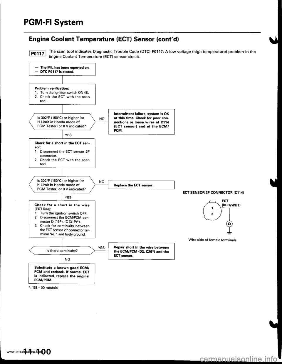
[F011' The.scan tool indicates Diagnostic Trouble Code (DTC) P0117: A low voltage (high temperature) problem in the: Engine Coolant Temperature (ECT) sensor circuit.
ECT SENSOR 2P CONNECTOR {C114I
Wire side of female terminals
- The MIL has been rooortod on.- DTC ml17 is sto.od.
Problem verification:1. Turn the ignition switch ON {ll).2. Check the ECT with the scantool,
Intermittont f.ilure, sysiom is OKat thk time. Check for poor con-nections or loo3e wire3 at C1lil(ECT sensorl and et the ECM/PCM.
ls 302"F (150'C) or higher (or
H Limit in Honda mode otPGM Tester) or 0 V indicated?
Check for a Bhort in the ECT sen-301:'1. Disconnect the ECT sensor 2Pconnefior,2. Check the ECT with the scantool.
ls 302"F (150"C)or higher (or
H-Limit in Honda mode ofPGM Tester) or 0 V indicated?
Check for r shorl in the wirs(EgT linel:1. Turn the ignition switch OFF.2. Disconnect the ECM/PCM con-nector D (16P), (C (31P)*1.3. Check tor continuity betweenthe ECT sensor 2P connectorterminal No. 1 and bodyground.
Repair short in the wir€ betweenthe ECM/FCM (D2, C26rl ,nd th6ECT senaor.
ls there continuity?
Substitute a known-good ECM/PCM and recheck. It normal ECTi! indicatod, replaco the oiiginalECM/PCM.
*:'98 - 00 models
1-1
www.emanualpro.com
Page 303 of 1395
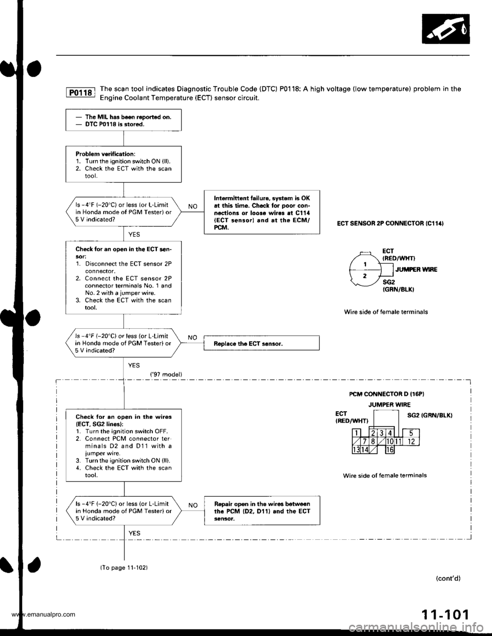
The scan tool indicates Diagnostic Trouble Code {DTC) P0118: A high voltage {low temperature) problem in the
Engine Coolant Temperature (ECT) sensor circuit.
ECT SENSOR 2P CONNECTOB (C11ill
ECT(ncD/wlrT)
ECTIREDAAIHT)
Wirc side of lemale terminals
sG2(GRN/8LKI
PCM CONNECTOR D {T6PI
JUMPER WIRE
JUi,IPEB WNE
IGRN/BLX}
Wire side oI female terminals
(cont'd)
1 1-101
The MIL has be€n reported on.DTC P01'18 is stor€d.
Problem verification:1. Turn the ignition switch ON {ll).2. Check the EcT with the scantool-
Intermiftent tailu.€,3ystem is OKat this time, Checl foJ poor con-n€ction3 or loose wires et C1'14(ECT ren3or) and at the ECM/PCM.
ls -4"F (-20'C) or less (or L-Limitin Honda mode ot PGM Tester) or5 V indicated?
Check for an open in the ECT sen-
1. Disconnect the ECT sensor 2Pconnector.2. Connect the ECT sensor 2Pconnector terminals No. 1 andNo. 2 with a jumper wire.3. Check the ECT with the scantool.
ls -4'F (-20'C) or less (or L'Limitin Honda mode of PGM Tester)or5 V indicated?
Check for an open in the wiies{ECT, SG2 lines):1. Turn the ignition switch OFF.2. Connect PCM connector terminals D2 and D11 with a
iumper wire.3. Turn the ignition switch ON {ll}.4. Check the ECT with the scantool,
ls -4"F (-20'C) or less (or L-Limitin Honda mode of PGM Testerior5 V indicated?
Repair open in th6 wire! botwe€nthe PCM lD2, D'l1l and the ECT3€n30t.
('97 model)
(To page 11-102)
www.emanualpro.com
Page 304 of 1395
PGM-FI System
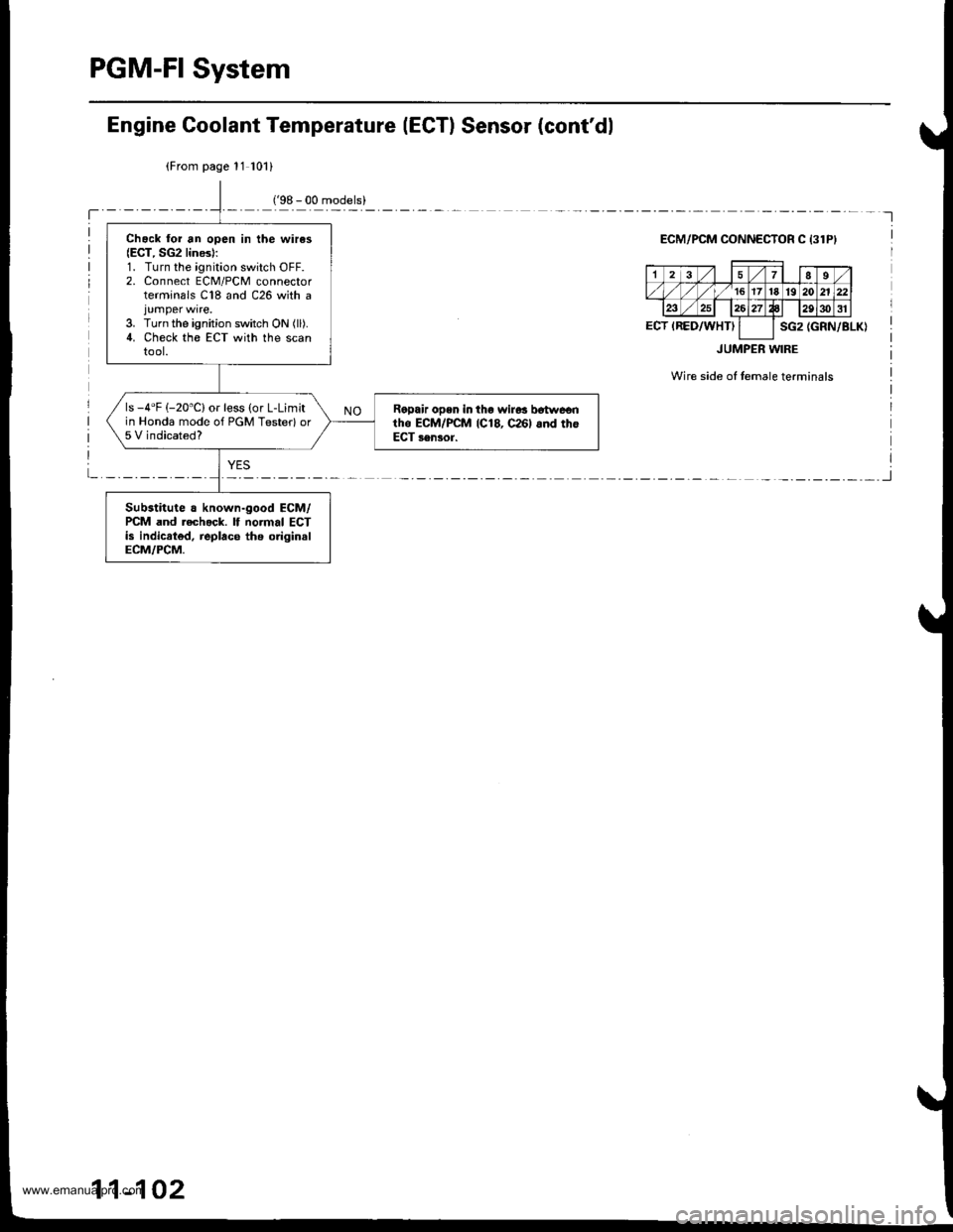
Chack lor an open in the wires(ECT, SG2 lines):1. Turn the ignition switch OFF.2. Connect ECM/PCM connectorterminals C18 and C26 with a
3. Turn the ignition switch ON (ll).
4. Check the ECT with the scantool.
ls -4"F (-20"C) or less (or L-Limitin Honda mode of PGM Testerlor5 V indicated?
Ralpair open in tho wir6s b6twe€ntho ECM/PCM 1C18, c26l 6nd thoECT sensor.
Substitute a known-good ECM/PCM and rech.ck. lf normal ECTis indicrted, replace ths originslECM/PCM.
Engine Goolant Temperature (ECTI Sensor (cont'dl
(From page 11 101)
ECM/PCM OONNECTOR C 13lPI
(GRN/BLK)
JUMPER WIRE
Wire side of temale terminals
17I9
,/ 1617't8'1920n
ECT IRED/WHTIsG2
11-102
www.emanualpro.com
Page 371 of 1395
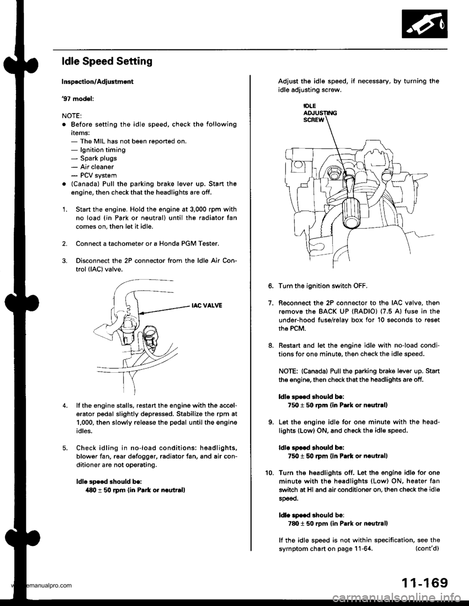
ldle Speed Setting
Inspoction/Adiustmont
37 modsl:
NOTE:
. Before setting the idle speed, check the following
items:- The MIL has not been reportsd on.- lgnition timing- Spark plugs
- Air cleaner- PCV system
. lcanada) Pull the parking brake lever up. Stan the
engine, then check that the headlights are off.
1. Start the engine. Hold the engine at 3,000 rpm with
no load (in Park or neutral) until the radiator fan
comes on, then let it idle.
Connect a tachometer or a Honda PGM Tester.
Disconnect the 2P connector from the ldle Air Con-
trol (lAC) valve.
IAC VALVE
lf the engine stalls, restart the engine with the accel-
erator pedal slightly depr6ss6d, Stabilize the rpm at
1,000, then slowly release the pedal until the engine
idles.
Check idling in no-load conditions: hsadlights,
blower fan, rear d€fogger, radiator fan, and air con-
ditioner are not operating.
ldle spood should b.:
{80 t 50 rpm {in Park or noutr.ll
IDLE
7.
Adjust the idle sp6ed,
idle adjusting screw.
if necessary, by turning the
Turn the ignition switch OFF.
Reconnect the 2P connector to the IAC valve, then
remove the BACK UP (RAD|Ol (7.5 Al fuse in the
under-hood fuse/rslav box for 10 seconds to reset
the PCM.
Restart and let the engine idle with no-load condi-
tions for one minute, then check the idle speed.
NOTE: (Canadal Pullthe parking brake lever up. Stan
the engine, then check that the headlights are off.
ldlo Ep€ed rhould be:
75O t 50 rpm (in P.rk or noutr.ll
Let the engine idl6 for one minute with the head-
lights (Low) ON, and check th€ idl€ speed.
ldle lpcod 3hould bo:
750 t 50 ]pm (in Park or nautlal)
Turn the headlights off. Let th€ engine idle for one
minute with the headlights (Low) ON, heater fan
switch at Hl and air conditioner on. then check the idle
sDeeo.
ldl. specd should b6:
7d) 1 50 rpm {in Park or nautral}
lf the idle speed is not within specification, see the
symptom chart on page 11-64. (cont'd)
1 1-169
www.emanualpro.com
Page 410 of 1395
Emission Control System
Evaporative Emission (EVAP) Controls (cont'd)
99 - 00 models:
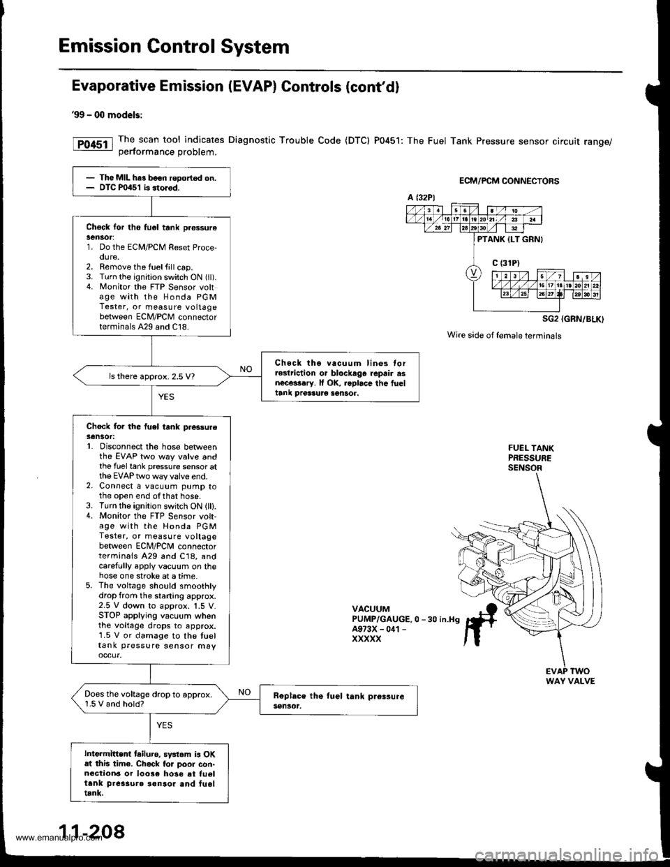
The scan tool indicates Diagnostic Trouble Code {DTC) P0451: The Fuel Tank Pressure sensor circuit range/oerformance Droblem.
ECM/PCM CONNECTORS
SG2 {GRN/BLK)
Wire side of {emaleterminals
FUEL TANKPRESSURESENSOR
VACUUMPUMP/GAUGE.0 -30 in.H9A973X - 041 -
XXXXX
- The MIL har been rooort€d on.- DTC P0451 b storod.
Check lor th6 tu6l tank pr€ssurelen30r:1. Do the ECM/PCM Reset Proce,oure.2. Remove the fuelfill cap.3. Turn the ignition switch ON (ll).4. Monitor the FTP Sensor voltage with the Honda PGMTester, or measure voltagebetween ECM/PCM connectorterminals A29 and C18.
Chock tho vacuum lin6s torrGlriction o. blockago repair asnecessary. lf OK, roplace the fueltank Drer3ur€ sentor.
ls there approx. 2.5 V?
Check for the fuel tank piessureSensot:L Disconnect the hose betweenthe EVAP two way valve andthe fuel tank pressure sensor atthe EVAP two way valve end.2. Connect a vacuum pump tothe open end ofthat hose.3. Turn the ignition switch ON (lll.4. Monitor the FTP S€nsor volt-age with the Honda PGMTester, or measure voltagebetween ECNI/PCNI connectorterminals A29 and C18, andcarefully appiy vacuum on thehose one stroke at a time.5. The voltage should smoothlydrop from the staning approx.2.5 V down to approx. 1.5 V.STOP applying vacuum whenthe voltage drops to approx.1.5 V or damage to the tueltank pressure sensor may
Does the voltage drop to approx.1.5 V and hold?
Intermittent tailuro. sv3tem is OKat this tim€. Chack to. poor con-n€ction6 or 10036 hose at fu6ltank pres3ure ionsor and fueltrnk.
a t32Pl
PTANK ILT GRNI
WAY VALVE
11-208
www.emanualpro.com
Page 411 of 1395
'98 - 00 mod€ls:
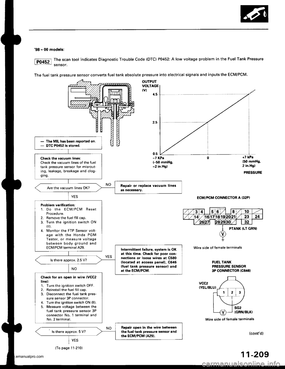
The scan tool indicates Diagnostic Trouble Code (DTC) P0452: A low voltage problem in the Fuel Tank Pressure
sensof.
The fuel tank Dressure sensor converts fuel tank absolute pressure into electrical signals and inputs the ECM/PCM.
OUTPUTVOLTAGEtvl{.5
0,5-? KPA(-50 mmHg,-2 in.Hgl
+7 kPr
l5O mmHg,2 in.Hgl
PRESSURE
ECM/PCM CONNECTOR A (32P)
Wire side ot female terminals
FUEL TANKPRESSURE SENSOR3P CONNECTOR tc6a6l
voc2(YEL/BLUI
Wire side ol fsmale terminals
(cont'd)
11-209
Th. MIL has been reoorted on.DTC m452 is stored.
Check the vacuum lin6:Check the vacuum lines of the fueltank pressure sensor for misrouting, leakage, breakage and clog-ging.
Are the vacuum lines OK?
Problem veriticstion:1. Do the ECM/PCM ResetProcedure-2. Remove the luelfillcap.3. Turn the ignition switch ONfl r).4. Monitor the FTP Sensor volt'age with the Honda PGMTester, or measure voltagebetween body ground andECM/PCM terminalA29.Intermittent failuro, system is OKat this lima. Chack lor Door con-nections or loose wi.es at C580llocrted rt access panell, C646lluel tank Daessure sensor) andat the ECM/PCM.
ls lhere approx. 2.5 V?
Check lor an open in wir€ lVeC2line):1. Turn the ignition switch OFF.2. Reinstallthe fuel fill cap.3. Disconnect the fuel tank pres-
sure sensor 3P connector,4. Turn the ignition switch ON (ll).
5- Measure voltage between thefLrel tank pressure sensor 3Pconnector No. 1 terminal andNo.2 terminal.
Replir opon in the wire b€tw€enth6 tuel tank pressure lensot andthe ECM/PCM {A29).ls there approx. 5 V?
YES
(To page 11-210)
www.emanualpro.com
Page 413 of 1395
'98 - 00 modals:
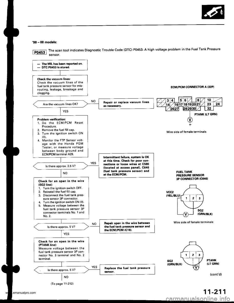
The scan tool indicates Diagnostic Trouble Code (DTC) P0453: A high voltage problem in the Fuel Tank Pressure
sensor.
ECM/PCM CONNECTOR A {32PI
Wire sido ot fema16 t€rminals
FUEL TANXPf,ESSUBE SENSOR3p CONNECTOR {C6,a6l
vcc2IYEL/BLUI
sG2IGRN/BLKI
sG2(GRN/BLK}
Wire side ot female terminals
PTANKILT GRNI
(cont'd)
11-211
PTANK ILT GRN)
123
Thc MIL has b6on ropottcd on.DTC mia53 is dorcd.
Ch6ck tho vacuum linos:Check the vacuum lines of the
fuel tank pressure sensor lor mis-
routing, leakage, breakage and
cloggrng.
Are the vacuum lines OK?
Problorn verif ication:1. Do the ECM/PCM ResetProcedute.2. Remove the fuel fill cap.
3. Turn the ignition switch ON
{[).4. Monitor the FTP Sensor volt-age with the Honda PGM
Tester, or measure voltagebetween body ground and
ECM,PCM terminal429.Intarmittent tailuro, sv3iom b OKat this timo. Chock for poor con-nection3 or loo$ wire3 at C580(locstod .t .cc$r p.nell, C6a6(fucl tank pros3ure son3orl and.t the ECM/FCM.
ls there approx. 2.5 V?
Check lor an open in tho wiro
lSG2lin6l:1. Turn the ignition switch OFF.
2. R6installthe Iuel fill cap.3. Disconnect the Iu6l tank pres_
sure sensor 3P connector,4. Turn the ignition switch ON (ll).
5. M€asure voltago between thetuel tank pressure sensor 3P
connector terminals No. '! andNo.2.
Replir op€n in th. wi.c b€{weentha fuel tank Dio'sute sansot andtho EC|,/PCM {Cl8}.ls there approx. 5 V?
Ch€ck for an opon in tho wiro(PTANK linel:Measure voltage between thefuel tank pressure sensor 3P con-nector No. 3 terminal and No. 2terminal.
ls there approx. 5 V?
\To page 11-212)
www.emanualpro.com
Page 416 of 1395
Emission Control System
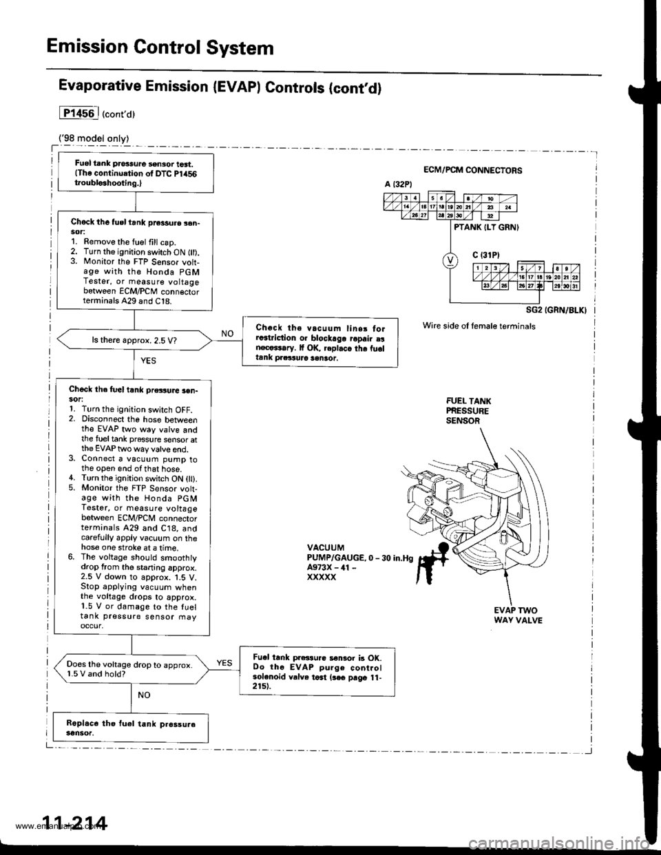
Fuel tank pros3ure sensor tost.(The continuetion of DTC Pl456t.oubls3hooting.,
Chock the tusl trnk pr€3sure sen-sor:1. Remove the fuel fill csp.2. Turn the ignition switch ON fll).3. Monitor the FTP Sensor voh-age with th€ Honda PGMTester, or measure voltagebetween ECM/PCM conn€ctorterminals A29 and C18.
Choct ths vacuum linsr forra3triction o. blockago ropair a!nect*rary. It OK, replaca the fu6ltank praituJc sentot.
ls there approx. 2.5 V?
Check the fuel t nk pressuae 3en-sor:1. Turn the ignition switch OFF.2. Disconnect the hose betweenthe EVAP two way valve andthe tueltank pressure sensor atthe EVAP two way valve end.3. Connect a vacuum pump tothe open end ofthat hose.4. Turn the ignition switch ON 0l).5. Monitor the FTP Sensor volt-age with the Honda PGMTestet, or measure voltagebetween ECM/PCM connectorterminals 429 and C18, andcarefully apply vacuum on thehose one stroke at a lime.6. The voltage should smoothtydrop from the staning approx.2.5 V down to approx. 1.5 V.Stop applying vacuum whenthe voltage drops to approx.1.5 V or damage to the fueltank pressure sensor fiayoccur,
Fu.l tank pressu.c a€nlor b OK.Oo thc EVAP pulge controlsolenoid valve toat (3€€ prgo 11-2151.
Does the voltage drop to approx.1.5 V and hold?
Evaporative Emission (EVAPI Controls (contd)
lP14s6l("ont,a)
ECM/PCM CONNECTORS
SG2 IGRN/BLKI
Wire side oI female terminals
FUEI- TANKPRESSURESENSOR
VACUUMPUMP/GAUGE,0 - 30 in.HgA973X - ill -
xxxxx
EVAP TWOWAY VALVE
11-214
www.emanualpro.com