Page 701 of 1395
![HONDA CR-V 2000 RD1-RD3 / 1.G Workshop Manual
ai_la2,
(41/4.:4.
\7)
1.0)tl
(3]
t9.1q
oo,ID@,8!Itt\,29
€4
69
aa.21
600toa
04
6!)ent00t.@
ATF FEED PIPE, I x 145 mm
ATF STRAINERSERVO BODYSERVO SEPARATOB PLATESECONDABY VALVE BOOYDOWEL PINSECONDAR HONDA CR-V 2000 RD1-RD3 / 1.G Workshop Manual
ai_la2,
(41/4.:4.
\7)
1.0)tl
(3]
t9.1q
oo,ID@,8!Itt\,29
€4
69
aa.21
600toa
04
6!)ent00t.@
ATF FEED PIPE, I x 145 mm
ATF STRAINERSERVO BODYSERVO SEPARATOB PLATESECONDABY VALVE BOOYDOWEL PINSECONDAR](/manual-img/13/5778/w960_5778-700.png)
ai_la2',
(41/4.:4.
\7)
1.0)tl
(3]
t9.1q
oo,ID@,8!Itt\,29
€4
69
aa.21
600toa
04
6!)ent00t.@
ATF FEED PIPE, I x 145 mm
ATF STRAINERSERVO BODYSERVO SEPARATOB PLATESECONDABY VALVE BOOYDOWEL PINSECONDARY SEPARATOR PLATE
SERVO DETENT BASE ('98 model onlvl
ATF FEED PIPE, 8 x 145 mmATF FEED PIPE.8 x 40 mmATF FEED PIPE,8 x 62 mmATF FEED PIPE, I x 112 mm
ATF FEED PIPE, 8 x 192.5 mm
ATF FEED PIPE, 8 x 105.8 mm
STOP SHAFT BRACKETATF LUERICATION PLATEATF FEED PIPEDOWEL PINLOCK-UP VALVE BODYLOCK-UP SEPARATOR PLATE
REGULATOR VALVE BOOYDOWEL PINCOOLER RELIEF VALVE SPRINGCOOLER BELIEF VALVETOROUE CONVERTER CHECK VALVE SPRING
TOROUE CONVERTER CHECK VALVECONTNOL SHAFTDETENT ARM SPRINGDETENT ARMDETENT ARM SHAFTFILTER Replace.CHECK BALLS1ST ACCUMULATOR CHOKEO-RING Replace.STATOR SHAFTSTOP SHAFTATF FEED PIPE. 8 x 112 mmMAIN VALVE BODYATF PUMP DRIVEN GEAR SHAFTATF PUMP DRIVEN GEAR
MAIN SEPARATOR PLATE
DOWEL PINATF PUMP DRIVE GEARSUCTION PIPE COLLARCOUNTEBSHAFT TOROUE CONVERTER HOUSING
BEARINGATF GUIDE PLATEATF MAGNETTOBOUE CONVERTER HOUSINGOIL SEAL Beplace.MAINSHAFT OIL SEAL Replace.MAINSHAFT TOROUE CONVERTER HOUSING
BEARINGLOCK.UP CONTROL SOLENOID VALVE A/B
FILTER/GASKET Replace.LOCK-UP CONTROL SOLENOID VALVE A/B
ASSEMELY
i4ll(4d
@@.!!l
art)@@@@li]t
TOROUE SPECIFICATIONS
Bolt/Nut No.Torque ValueSizeRemarks
12 N.m (1.2 kgim,8.7 lbf'tt)6x1.0mm
14-185
www.emanualpro.com
Page 767 of 1395

1.Install the suction pipe collar and the ATF magnet
{2WD) in the torque converter housing, if necessary.
lnstall the main seDarator Dlate and the two dowel
pins on the torque converter housing,
Install the ATF pump drive gear. ATF pump driven
gear, and ATF pump driven gear shaft on the torque
converter housing. Installthe ATF pump driven gear
with its grooved and chamfered side facing down.
ATF PUMPGEAR
ATF PUMP D{IVEf{GEAR SHAFT
ATF PUi'PORIVEN GEAR
Grooved and chamteredside faces separatorplate.
MAIN S€PAR/ATORPLATE
5.
o.
Loosely install the main valve body with five bolts.
Make sure the ATF pump drive gear rotates smoothly
in the normal operating direction, and the ATF pump
driven gear shaft moves smoothly in the axial and
normal operating directions.
Install the secondary valve body, separator plate,
and two dowel pins on the main valve body. Do not
installthe bolts.
Install the control shaft in the housing along with
the manual valve.
lnstall the detent arm and arm shaft in the main
valve body, then hook the detent arm spring to the
detent arm.
SEBVO SEPARATOR PLATE
7.
DETENT ARMSHAFT
OETENT ARM
CONTROLSHAFT
MANUAL VAIVE
OETENT ARM SPRING
onlv on the '98 - 00 models,
14-251
1l.
9.
8.
10.
Install the servo body and separator plate on the
secondary valve body ('97 - 98 models: seven bolts,'99 - 00 models: eight bolts).
lnstall the servo detent base ('97 - 98 models only)
and the ATF strainer ('97 - 98 models: two bolts,'99 -
00 models: one boltl.
Tighten the five bolts on the main valve body to 12
N'm (1.2 kgf.m, 8.7 lbf.ft).
Make sure the ATF pump drive gear and ATF pump
driven gear shaft move smoothly. lf they don't,
loosen the bolts on the main valve body, and disas-
semble the valve bodies. Realign the ATF pump driv-
en gear shaft and reassemble the valve bodies, then
retighten the bolts to 12 N.m (1.2 kgim, 8.7 lbf.ft).
CAUTION: Failure to align the ATF pump driven
gear shaft corroctly will rosult in a seizsd ATF pump
drive gear or ATF pump drivon gear shaft.
ATF PUMP ATFGEARDRIVE GEAR DBIVEN GEARSHAFT
Install the stator shaft and stop shaft
Install the bolts and the stop shaft bracket on the
secondary valve body, then tighten the bolts (three
bolts).
Install the torque converter check valve, cooler relief
valve, and valve springs in the regulator valve body,
then install the regulator valve body on the main
valve body {one boltl.
Install the lock-up valve body, separator plate, two
dowel pins and lubrication plate (eight bolts).
Installthe one ATF feed pipe in the main valve body,
the three ATF feed pipes in the secondary valve, the
three ATF feed pipes in the servo body and the one
ATF feed pipe in the lock-up valve body.
NOTE: lnstall the 105.8 mm ATF feed pipe with its
filter side away from the secondary valve body; the
filter is on the 105.8 mm ATF feed pipe, which is(cont'd)
13.
14.
15.
16.
www.emanualpro.com
Page 781 of 1395

17.Make sure the transmission is in E position.
Fill the transmission with ATF, and run the engine
for 30 seconds or until approximately 0.951 {1.0 US
qt., 0.8 lmp qt.) is discharged.
Remove the drain hose, and reconnect the cooler
return hose to the transmission (see page 14-266).
Refill the transmission with ATF to the proper level
(see page l4'161 ).
18.
19.
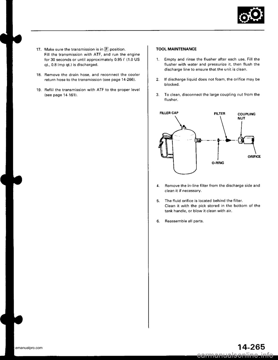
TOOL MAINTENANCE
1. €mpty and rinse the flusher after each use. Fill the
flusher with water and pressurize it, then flush the
discharge line to ensure that the unit is clean.
2. lf discharge liquid does not foam, the orifice may be
blocked.
3. To clean, disconnect the large coupling nut from the
flusher.
FILTER
\-0--D
I
IO.RING
Remove the in-line filter from the discharge side and
clean it if necessary.
The fluid orifice is located behind the filter.
Clean it with the pick stored in the bottom of the
tank handle, or blow it clean with air.
Reassemble all parts.
COUPLINGNUT
II
-@q
\ORIFICE
4.
5.
6.
FILLER CAP
14-265
www.emanualpro.com
Page 1091 of 1395

Air Conditioning
Heater Control Panel
Reofacement ,.,...,,.,..,.,.,,22-46
Blower Unit
Replacement .................. 22-46
Overhaul ...........,,,., .......-.22-17
Evaporalor
ReDlacement ...,.,.,..,......,22-4A
Overhaul ................ .........22-19
A/C Filter
Replacement ..................22-50*Heater Unit
ReDfacement ..................22-50
Overhaul ..,.,..,.,...,.. .........22-52
Temperature Control
Adiustment ....................22-53
A/C Service Tips and Precauiions............-....-.... 22-54
A/C System Torque Specifications .................... 22-55
A/C System Service
Performance Test ......,...22-56
Pressure Test Chart .-.....22-5a
Recovery ..............,. ...-.-...22-59
Evacuation -...........-........22-60
Charging ................ .......-.22-61
Leak Test ........................22-61
Compressor
Repfacement ..........-.......22-62
flfustrated Index .....,.......22-64
Cfutch fnspection .........,.22-65
Cfutch Overhaul ............- 22-66
Thermaf Protector Rep|acement ................... 22-68
Refief Valve Replacement .............................. 22-68
A/C Comoressor Belt
Adiustment .................... 22-69
Condenser
Repfacement .,.....,,.,..,.,..22-70
'Read SRS precautions betore working in this area.
www.emanualpro.com
Page 1139 of 1395

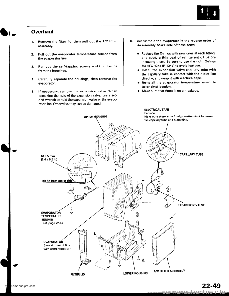
}-Overhaul
1. Remove the filter lid. then pull out the A/C filter
assembly.
Pull out the evaporator temperature sensor from
the evaporator fins.
Remove the self-tapping screws and the clamps
from the housings.
Carefully separate the housings, then remove the
evaporator.
lf necessary, remove the expansion valve When
loosening the nuts of the expansion valve, use a sec-
ond wrench to hold the expansion valve or the evapo-
rator line. Otherwise, they can be damaged.
6. Reassemble the evaporator in the reverse order of
disassembly. Make note of these items.
. Replace the O-rings with new ones at each fitting,
and apply a thin coat of refrigerant oil before
installing them. Be sure to use the right O-rings
for HFC-'134a (R-134a) to avoid leakage.
. Install the expansion valve capillary tube with
the capillary tube in contact with the outlet line
directly, and wrap it with electricaltape.
. Reinstall the evaporator temperature sensor to
its original location.
. Make sure that there is no air leakage.
ELECTRICAL TAPEReplace.Make sure there is no foreign matter stuck between
the capillary tube and outlet line.
CAPILLARY TUAE
EXPANSION VALVE
4.
TEMPERATURESENSORlest, page 22-41
,m
\!{
YFILTER LID
;
I-OWER HOUSINGA/C FILTER ASSEMBLY
22-49
www.emanualpro.com
Page 1140 of 1395

A/C FilterHeater Unit
Replacement
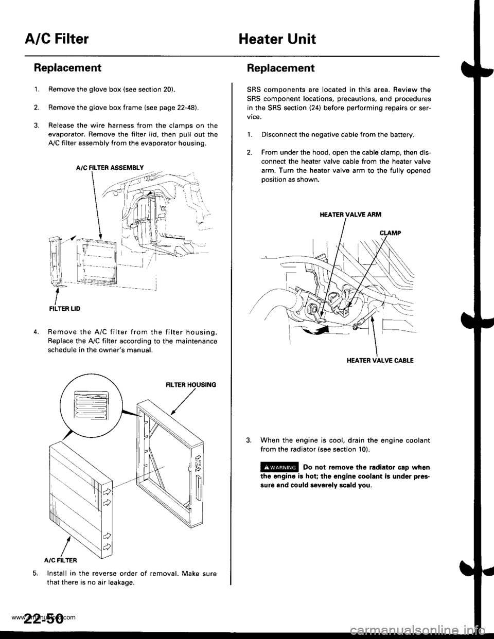
1.Remove the glove box (see section 20).
Remove the glove box frame {see page 22-4A).
Release the wire harness from the clamps on the
evaporator. Remove the filter lid, then pull out the
,VC filter assembly from the evaporator housing.
A/C FILTER ASSEMELY
Remove the A/C filter from the filter housing.
Replace the Ay'C filter according to the maintenance
schedule in the owner's manual.
Install in the reverse order of removal. Make sure
that there is no air leakage.
22-50
Replacement
SRS components are located in this area. Review the
SRS component locations, precautions, and procedures
in the SRS section {24) before performing repairs or ser-
1. Disconnect the negative cable from the battery.
2. From under the hood, open the cable clamp, then dis-
connect the heater valve cable from the heater valve
arm. Turn the heater valve arm to the fullv ooened
oosition as shown.
When the engine is cool, drain the engine coolant
from the radiator (see section 10).
@ Do not remove the rldiator cap when
the engine is hot; the engine coolant is under pres-
sure and could sevo.ely scald you.
HEATER VALVE ARM
HEATER VALVE CABLE
www.emanualpro.com