Page 359 of 1395

'98 - 00 models:ECM/PCM CONNECTORS
ECM/PCM CONNECTOR A (32PI
Wire side of female terminals
ECM/PCM CONNECTORS
A (32P1
ACC (BLK/REOI
LG1 (BRN/BLKI
{cont'd)
11-157
A {32P1
Check for a shott in the wire
{ACS linel:1. Turn the ignition switch OFF.
2. Disconnect the A/C Pressureswitch 2P connector.3. Turn the ignition switch ON (ll)
4. Measure vo ltage betweenECM/PCM connector terml
nals A27 and 820.
Check tor . short in the wire IACSlinel:1. Turn the ignition switch OFF.
2. Disconnect ECM/PCM connec-tor A (32P).
3. Check for continuity betweenbody ground and ECM/PCMconnector terminal A27.
ls there battery voltage?
R.oak short in the wile between
rhe ECM/PCM (A271 and the A/C
Dressure switch.ls there continuitv?
Sub6titute a known{ood ECM/
rcM and recheck. lf pte6cribed
voltage i3 now available, re'pl.ce the origioal ECM/rcM.See ih6 air conditioner inspec-
tion (s6e section 221.
Check for an open in the wire(ACC line):'1. Turn the ignition switch OFF.
2. Reconnect the A/C Pressureswitch 2P conneclor.3. Turn the ignition switch ON (ll).
4. Momentarily connect ECM/PCM connector terminals A17
and 820 with a jumPer wireseveralllmes,
{To page 11 158)JUMPER WIRE
www.emanualpro.com
Page 392 of 1395
Fuel Supply System
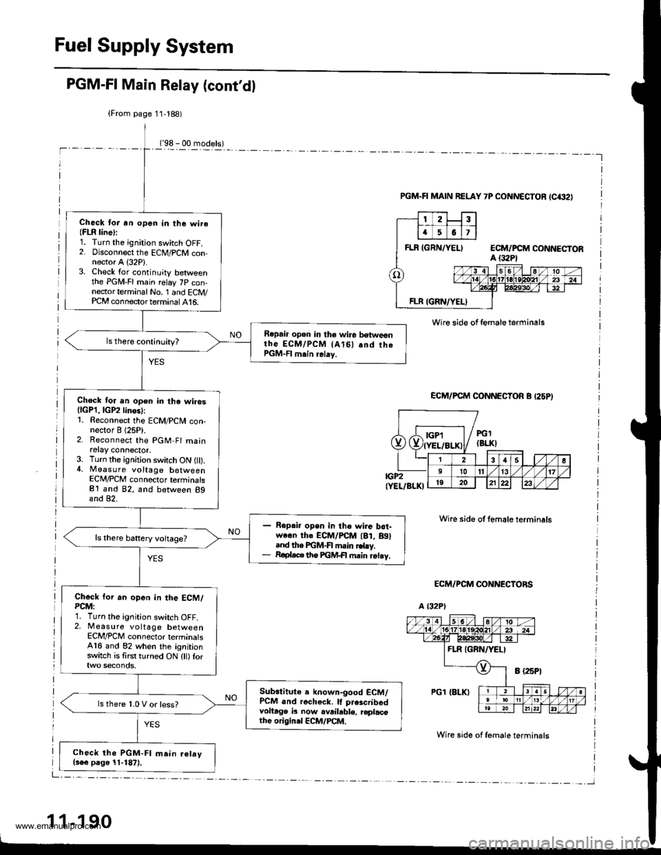
PGM-FI Main Relay (cont'dl
('98 - 00 models)-l
(From page 11,188)
Check lor an open in the wire(FLR line):1. Turn the ignition switch OFF.2. Disconnect the ECM/PCM connector A (32P1.3. Check for continuity betweenthe PGM-FI main relay 7P con-nector terminal No. '1 and ECM/PCM connector terminal 416.
Repaia open in the wire betweenthe EcM/PcM lAl5l .nd thePGM-FI m.in relay.
Check for an open in the wiresllcPl,lGP2linos):1. Reconnect the ECM/PCN4 con-nector I (25P).2. Reconnect the PGM Fl mainretay connector.3. Turn the ignition switch ON l).4, Measure voltage betweenECM/PCM connector terminalsB1 and 82, and between 89and 82.
Ropai. open in tho wire b6t-we€n th. ECM/PCM lBt, Btl.nd the FGM-FI main rd.y.R€plac€ th6 FGM+| main retay,
Chock for an open in the ECM/PCM:1. Turn the ignition switch OFF.2, Measure voltage betweenECM/PCM connector terminals416 and 82 when the ignitionswitch is first turned ON (tl) for
Subrtitute e known-good ECM/PCM and recheck. lf prescribsdvoltage b now ovrihble, replacothe originel ECM/PCM.
ls there 1.0 V or less?
Check the PGM-FI main.elav(s6e page 11-1871.
PGM.FI MAIN RELAY 7P CONNECTOF (C€2)
Wire sid€ of female terminals
ECM/PCM CONNECTOR B I25PI
IGP2(YEL/BLKI
ECM/PCM CONNECTORS
a t32Pl
Wire side of female terminals
Wire side of f€male terminsls
1 1-190
Dde"Jt;;liL-F-T--
PGl(BLK}
38s l1011131719202122
www.emanualpro.com
Page 615 of 1395
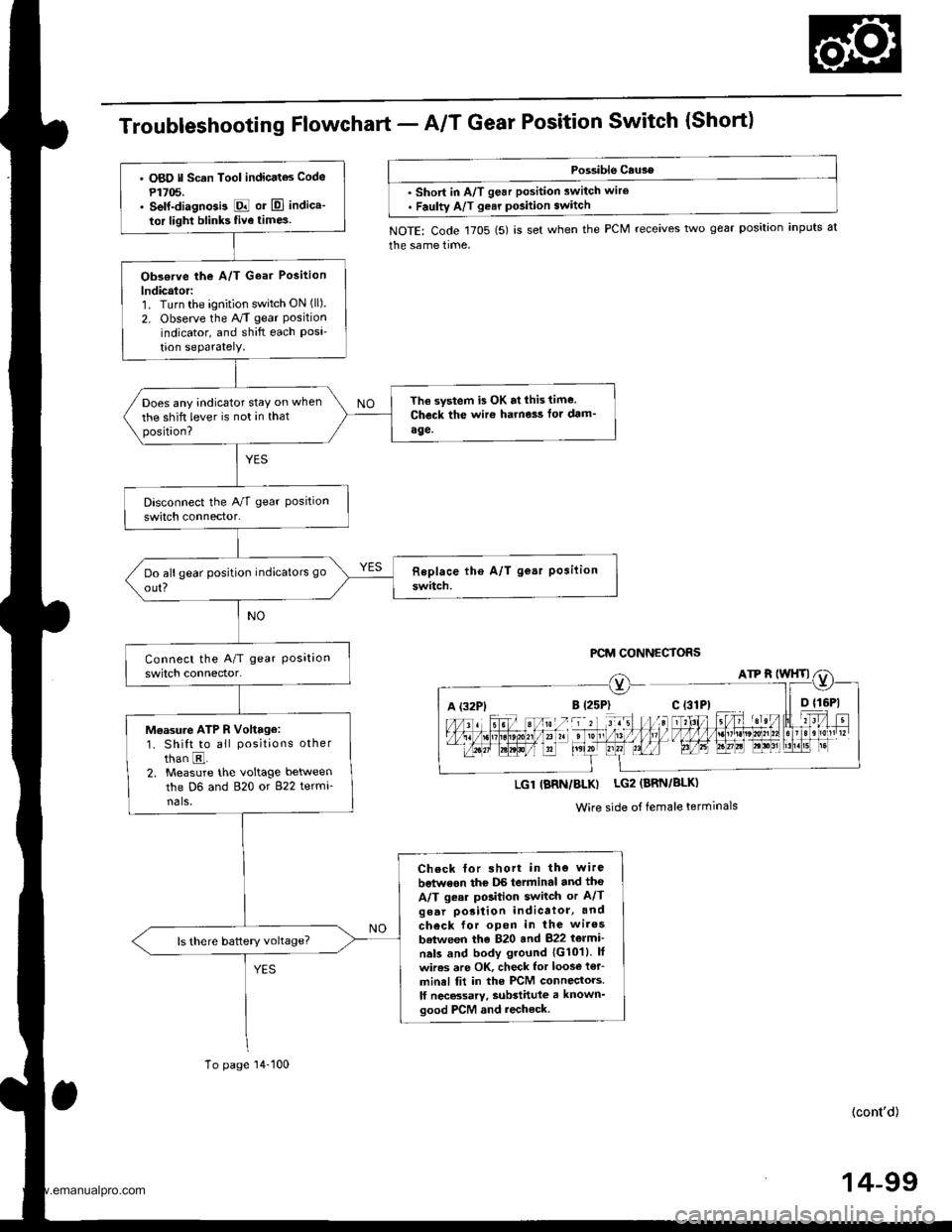
TroubleshootingFfowchart - AIT Gear Position Switch {Short)
Possible Cau3e
. short in A/T gear position switch wire. Faulty A/T gear pGition switch
NOTE: Code 1705 (5) is set when the PCM receives two gear position inputs at
the same time,
PCM CONNECTORS
A (32P1
LGl IBRN/BLK) LG2 (BRN/BLK)
Wire side of female terminals
' O8O ll Scan Tool indicatas Code
P1705.. self-diagnGi3 E or El indica'
tor light blinks five time3
Obs€rve the A/T Goar Position
lndicalor:1. Turn the ignition switch ON (ll).
2. Observe the A/T gear Positionindicator, and shift each Posi'tion seParatelY.
The system is OK at lhis time.
Check the wir€ harne3s fot dam'
age.
Does any indicator stay on when
the shift lever is not in thatposition?
Moasu.e ATP R Voltage:1. Shift to all positions other
than E.2. Measure the voltage between
the D6 and 820 or 822 termi-nals,
Check for short in the wire
betwoon thc DS terminal and tho
A/T gear position switch or A/Tgear porition indicatol, and
check for open in the wires
batween the 820 and 822 t6lmi'
nals and body ground 1G1011. lf
wires are OK, check lor loos€ i€r_
minel fit in the PCM connectors.
lf necBsarv, substittlle a known'good PCM and recheck.
To page'14-100
(cont'd)
14-99
www.emanualpro.com
Page 621 of 1395
From page 14-104
Measure ATP 1 Voliag€:1. Shift to E position.2, Measure the voltage betweenthe D15 and 820 or B22 termi-nals.
Repair open in the wire betweenthe D15 terminal and the A/Tgear poaition switch.
Check LG Wire tor an OpenCircuit:'1. Turn the ignition switch OFF.2. Check lor continuity betweenthe 820 terminal and bodyground, and between the 822terminal and body ground.
Repair open in th. wiresbetween the B20 and 822 tarmi-nals and body ground. and repairpoor ground {G101).
ls there continuity?
Check tor loose terminaltit in thePCM connectors. lf n6cassary,substitute d known-good PCMand recheck.
B t25Pl
FCM CONNECTORS
c t3lPtD tl6Pl
LGl IBRN/BLKI
LGl (BRN/BLKI
Wire side of female terminals
A (32P1B (2sP)c (31P|
14-105
www.emanualpro.com
Page 634 of 1395
ElectricalTroubleshooting ('98 - 00 Models)
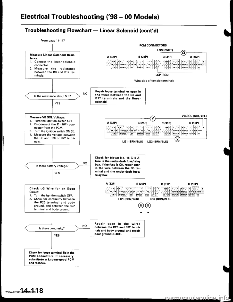
Troubleshooting Flowchaft - Linear Solenoid (cont'dl
Wire side of female terminals
LG2 {BRN/BLKI
From page 14-117
Measure Linea. Solenoid Resis-tance:1. Connect the linear solenoidconnector,2. Measure the resistancebetween the 88 and 817 termrnals,
Repair loose torminal oi open inthe wires between rhe 88 and817 terminals and the linearsolenoid.
ls the resistance about 5 O?
Measure VB SOL Voltago:1. Turn the ignition switch OFF.2. Disconnect the D 116P) con-nector trom the PCM.3. Turn the ignition switch ON (ll).4. Measure the voltage betweenthe D5 and 920 ot B22 tetmi-nals.
Check for blown No. 15 17.5 Alfuse in the under-da3h tus€/relaybox. lI the fuse is OK, rap.ir openin the wire betwe€n the D5 ter-minal and th€ under-dash tuso/relav box.
ls there baftery voltsge?
Check LG Wire for.n OpenCircuit:1. Turn the ignition switch OFF.2. Check for continuity betweenthe 820 terminal and bodyground, and between the 822terminal and body ground.
Repair op6n in the wirosbetwe€n the 820 and 822 termi-nals and body ground, and repairpoor g.ound iG101).
ls there continuity?
Chack tor loose terminel fit in thePCM connecto13. It nocosaary,substitute a known-good PCM.nd recheck,
a t32Plc t3lPl
LSP (REO)
a l32Pl
A (32P1
LGl IBRN/BLK}
B l2sP)c 13lPlD l16P)
14-118
www.emanualpro.com
Page 639 of 1395
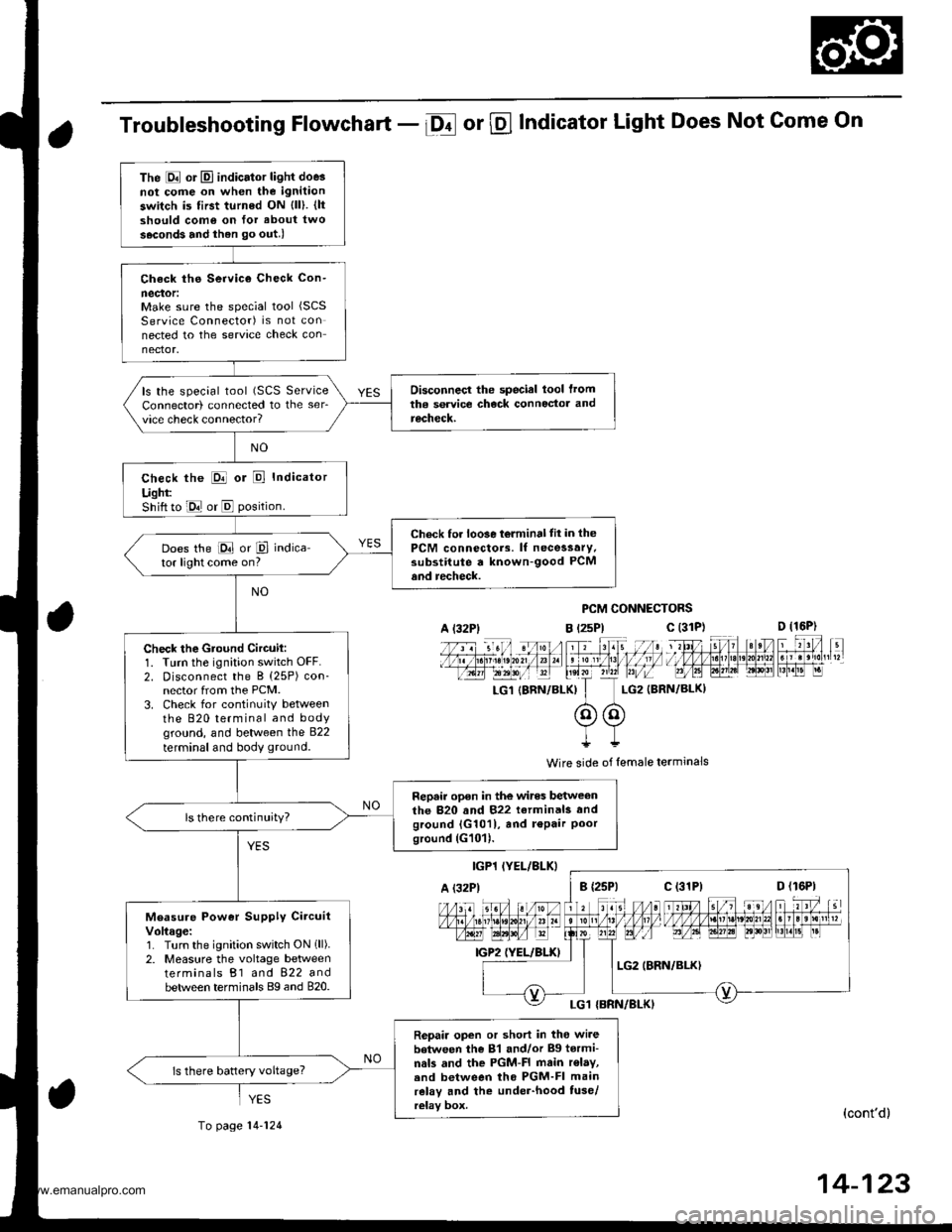
Troubleshooting Flowchart - Df or @ Indicator Light Does Not Come On
PCM CONNECTORS
B t2sPl c (31D (16P)
l*f4tr 8-
f - -- -6 3 rol ,: irr t lrpri$fe?0?r/a)1 e 'oI 13 11/ / l//|rrr I , ltelx ?r2? r,/i-T_LG1 {8RN/BI-KI I LG2 (BRN/BL()I
@@I++
Wire side of lemale terminals
(cont'd)
14-123
The E or El indicator light doe3not cofie on when the ignitaon
switch is first turned ON {ll). {ltshould como on for about two
s.cond3 and ihen go out.l
Check ths Service Check Con-
neclor:Make sure the special tool (SCS
Service Connector) is not connected to the service check connector.
Disconnecl the special lool lromtha service check connoctor andrecheck.
ls the special tool (SCS ServiceConnector) connected to the ser_vice check connector?
check the E or E Indicator
Ught:Shift to E or E position.
Check for loo3e t6lminal tit in thePCM connectors. lf necessary.substitute a known-good PCMand recheck.
Does the E or P indica-tor light come on?
Check the Gtound Circuil:1. Turn the ignition switch OFF.2. Disconnect the B (25P) con-nector from the PCM.3. Check for continuitY betweenthe 820 terminal and bodyground, and between the 822
terminal and body ground.
Repair open in the wires betweenthe 820 and 822 terminals andground {G1011, and r€Pair Poorground (G101).
ls there continuity?
Measure Power Supply CircuitVoltage:1. Turn the ignition switch ON 1ll).2. Measure the voltage betweenterminals B1 and 822 andbetween terminals Bg and 820.
Repair open or short in tho wi.ebetween the 81 and/or Bg tormi-nals and the PGM-FI main r€lay,.nd between tho PGM-FI mainrelay and the under-hood tuse/relay box.
ls there battery voltage?
A l32Plc (31P)
c (31P)
YES
To page 14-124
www.emanualpro.com
Page 1105 of 1395
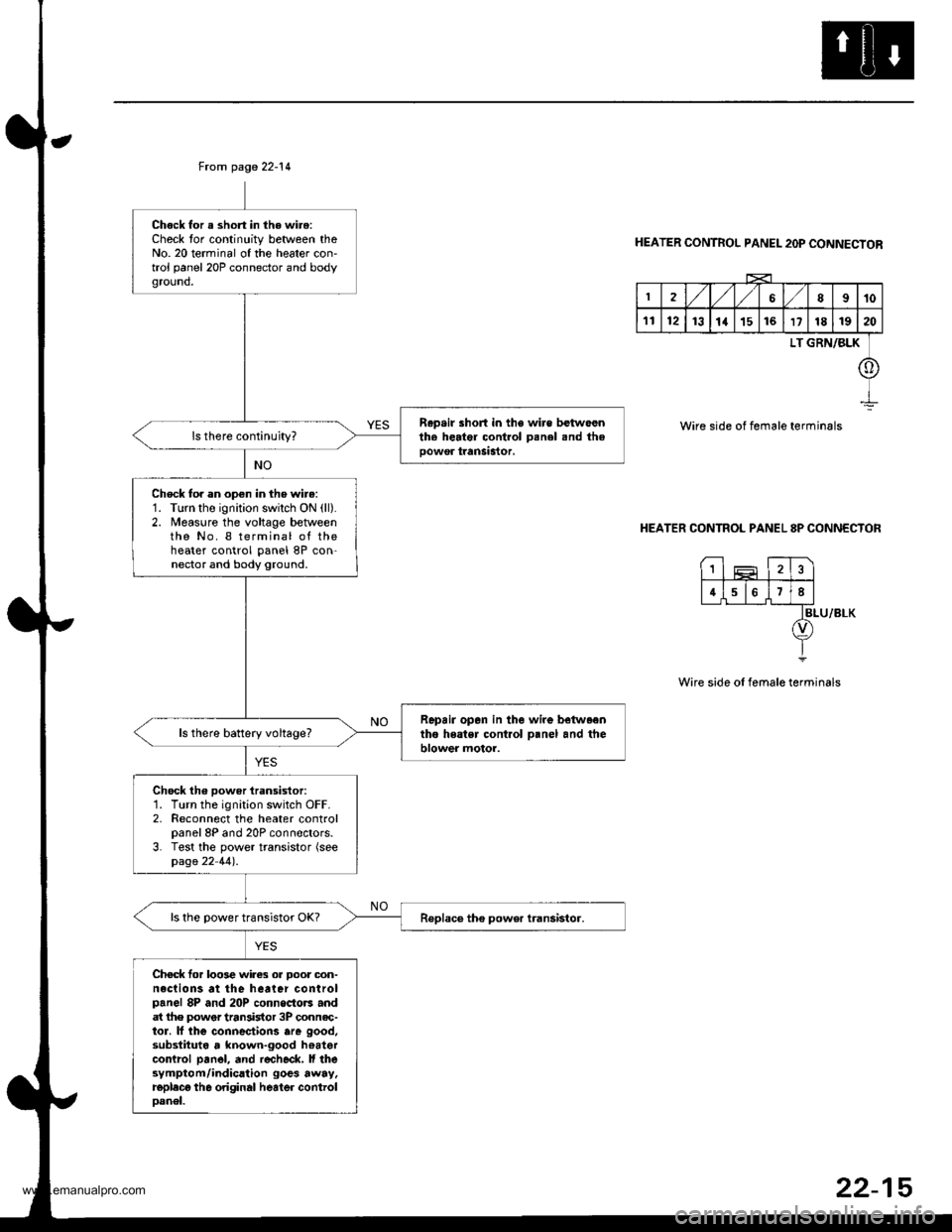
From page 22-14
Chock for a short in the wire:Check tor continuity between theNo. 20 terminal of the heater con'trol panel 20P connector and bodyground,
R.p.ir short in the wire betwoenth. herter control Denel snd theoowor tranSastor.
Check to. an open in the wire:1. Turn the ignition swilch ON (ll).
2. Measure the voltage betweenthe No. I terminal of theheater control panel 8P con-nector and body ground.
Repair opan in the wire betwaentho heatsr cont.ol o.nel and theblower motor.ls there battery voltage?
Chock th6 power iransistor:1. Turn the ignition switch OFF.2. Reconnect the heater controlpanel 8P and 20P connectors.3. Test the power transistor (seepage 22 44).
ls the power transistor OK?
Chec* for loo3e wires or Door oon-neclions at the heater controlpanel 8P and 20P connoctors andat lhe power tran3istor 3P connec-tor. lf lhe connectiorc are good,substituta , known-good hoatercontrcl pan6l, and r€check. ll thesymptom/indication goes away.replecg th6 original heater controloanel.
HEATER CONTROL PANEL 2OP CONNECTOR
2,/1,/l/68910
1112131a151617181920
LT GRN/BLK
o
Wire side of female terminals
HEATER CONTROL PANEL 8P CONNECTOR
BLU/8LK
Wire side of female terminals
1
4678
22-15
www.emanualpro.com
Page 1123 of 1395
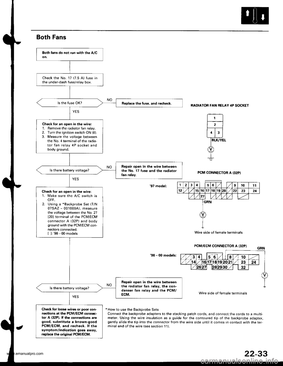
Both Fans
RADIATOR FAN RELAY 'P SOCKET
BLK/YEL
PCM CONNECTOR A I32PI
'9? model:
PCM/ECM CONNECTOR A (32PI
'98 - 0O mod6ls:
Wire side of female terminals
* How to use the Backprobe SetsConnect the backprobe adapters to the stacking patch cords, and connect the cords to a multimeter. Using the wire insulation as a guide for the contoured tip of the backprobe adapter,gently slide the tip into the connector from the wire side until it comes in contact with the terminal end ofthe ware {see section l1).
Check the No. 17 (7.5 A) tuse inthe under-dash fuse/relay box.
Reolace the tuse. and recheck.
Check for an op€n in the wire:1. Remove the radiator fan relay.2. TLrrn the ignition switch ON (ll).
3. Measure the voltage betweenthe No.4 terminalofthe radiator fan relay 4P socket andbody ground.
Repair open in the wire betweenlhe No. 17 luse and the radiatortan relay.
Check for an open in the wire:1. Make sure the A/C switch isOFF.2. Using a *Backprobe Set {T/N07SAZ - 001000A), measurethe voltage between the No. 27I20l terminal ol the PCM/ECMconnector A (32P) and bodyground with the PCM/ECM con-nectors connected.[ ]: '98 - 00 models
Repair open in the wire b€tweenthe.adiator fan ralav, the con-denser tan rolay and the PCM/ECM.
Check tor loose wires or poor con-nodions at the PCM/ECM connoc-tor A (32P1. lf the connections arcgood, substitute a known-goodPCM/ECM, and recheck. It thesymptom/indicalion goes away,r.plrce the original PCM/ECM.
1
2
1
12461011
12t5t61718r9222321
GRN
Wire side oI female terminals
22-33
www.emanualpro.com