2000 HONDA CR-V Ignition wires
[x] Cancel search: Ignition wiresPage 319 of 1395
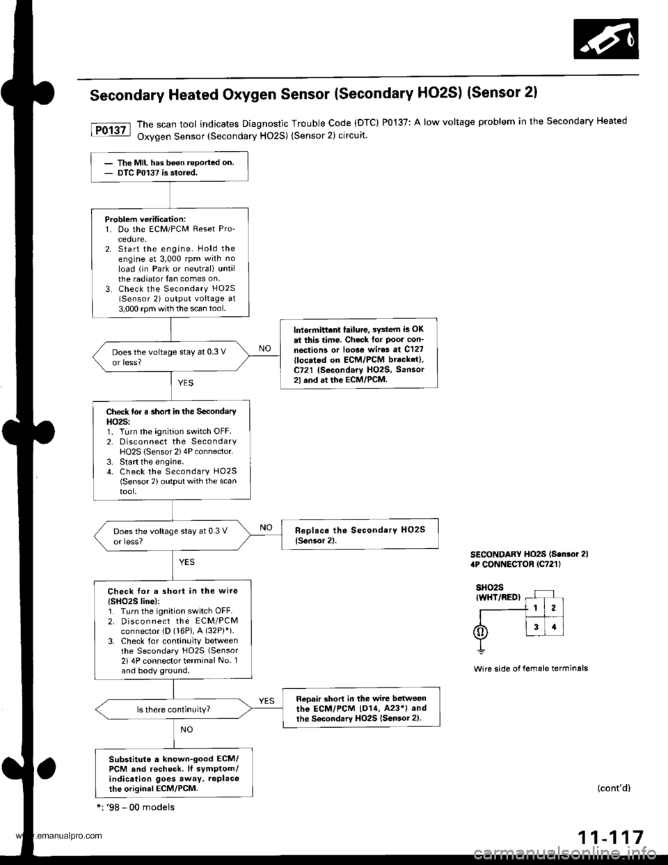
Secondary Heated Oxygen Sensor (Secondary HO2S) (Sensor 2)
The scan tool indicates Diagnostic Trouble code (DTC) P0137: A low voltage problem in the secondary Heated
Oxygen Sensor (Secondary HO2S) (Sensor 2) circuit.
SECONDARY HO2S ls.nlor 2)4P CONNECTOB lC721l
Wire side of lemale terminals
(cont'd)
11-117
The MIL hrs been reported on.DTC P0137 is stored.
Problem veritication:1. Do the ECM/PCM Reset Pro'cedure.2. Start the engine. Hold theengine at 3,000 rpm wilh no
load (in Park or neutral) untalthe radiator {an comes on,3. Check the Secondary H02S
lSensor 2) output voltage at3,000 rpm with the scan tool.
lnlermittent failure, 3ystem i5 OK
at this time. Check tor Poor con'
noction3 or loose wires at C127
{locatod on ECM/PCM bracket},C721 (Secondary HO2S, Sensor2l and at the ECM/PCM.
Does the voltage stay at 0.3 V
or less?
Check for a short in the SecondaryHO2S:1. Turn the ignition switch OFF.2. Disconnect the SecondaryHO2S lSensor 2) 4P connector.3. Start the engine.4. Check the Secondary HO25(Sensor 2) output with the scantool.
Check lor a short in the wire(SHO2S linel:1. Turn the ignition switch OFF.2. Disco n nect the ECM/PCMconnector {D (16P}, A (32P}').
3. Check for continuity betweenthe Secondary HO2S (Sensor
2i 4P connector terminal No. 1and body ground.
Reoair short in the wire b€twoen
rhe ECM/PCM |D14, 423*l and
the Secondary HO2S {Sensor 2).
Substitute a known-good ECM/PCM and rocheck. lf symptom/indication goes away, replacethe original ECM/PCM.
*: '98 - 00 modeis
www.emanualpro.com
Page 323 of 1395
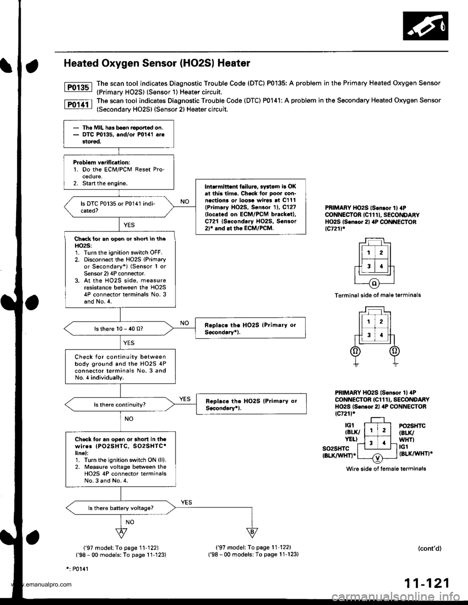
Heated Oxygen Sensor (HO2S| Heater
The scan tool indicatos Diagnostic Trouble Code (DTC) P0135: A problem in the Primary Heated Oxygen Sensor
{Primarv HO2S) (Sensor 1) Heater circuit.
The scan tool indicates Diagnostic Trouble Code (DTC) P0141: A problem in the Secondary Heated Oxygen Sensor
(Secondary HO2S) (Sensor 2) Heater circuit.
Fol3sl
Fo11tl
PBIMARY HO2S ls.n.or ll 4PCONNECTOR (CI 1 1 I, SECONDARYHO2S ls.n.o.2l aP CONNECTORlc721l.
Terminal side of male t€rminals
PRIMARY HO2S lson.o. 1l aPCONNECTOR {Cl 1 1 }, SECONDARYHO2S ls.nror 21 4P CONNECTORtcr21l.
so2sHTctBLK/WHn.
PO2SHTC(BLK/
WHTItGlIBLKAAIHTI'
Wire sid€ of lemale terminals
('97 model: To page '11-122)
('98 - 00 models: To page 11-'123)
*: P0141
('97 model: To page'11-122)
1'98 - 00 modelsl To page 11-123)(cont'd)
11-121
- Th6 MIL h.. bocn roponod on.- DTC P0135, and/oi mlal arestored.
Probl.m verification:1. Do the ECM/PCM Resot Pro-cedure,2. Start the engine.Int.rrnittaii frilurc, awtom ir OKat thi3 time. Chock lor poor con-n.ctiona or loosa wiro3 !t C111
lPrim.ry HO2S, Sen3o. 11. C12?llocatcd on ECM/PCM br.ck.t),C721 lsocond.ry Ho2s, s.n3or2r and at tho ECM/PCM.
Ch.ck ior an opon or shoYt in theHO2S:1. Turn the ignition switch OFF.2. Disconnoct the Ho2s (Primary
or Secondary*) (Sensor 1 orSensor 2)4P conneclor.3. At the HO2S side, measureresistance between the HO2S4P connector terminals No. 3and No.4.
ls there 10 - 40 0?
Check for continuity betweenbody ground and the HO2S 4Pconnector terminals No. 3 andNo. 4 individually.
Check tor an op6n or 3hort in thewires IPO2SHTC, SO2SHTC'linel:1. Turn the ignition swhch ON {ll).2. Moasure voltage between theHO2S 4P connector terminalsNo.3 and No.4.
www.emanualpro.com
Page 325 of 1395
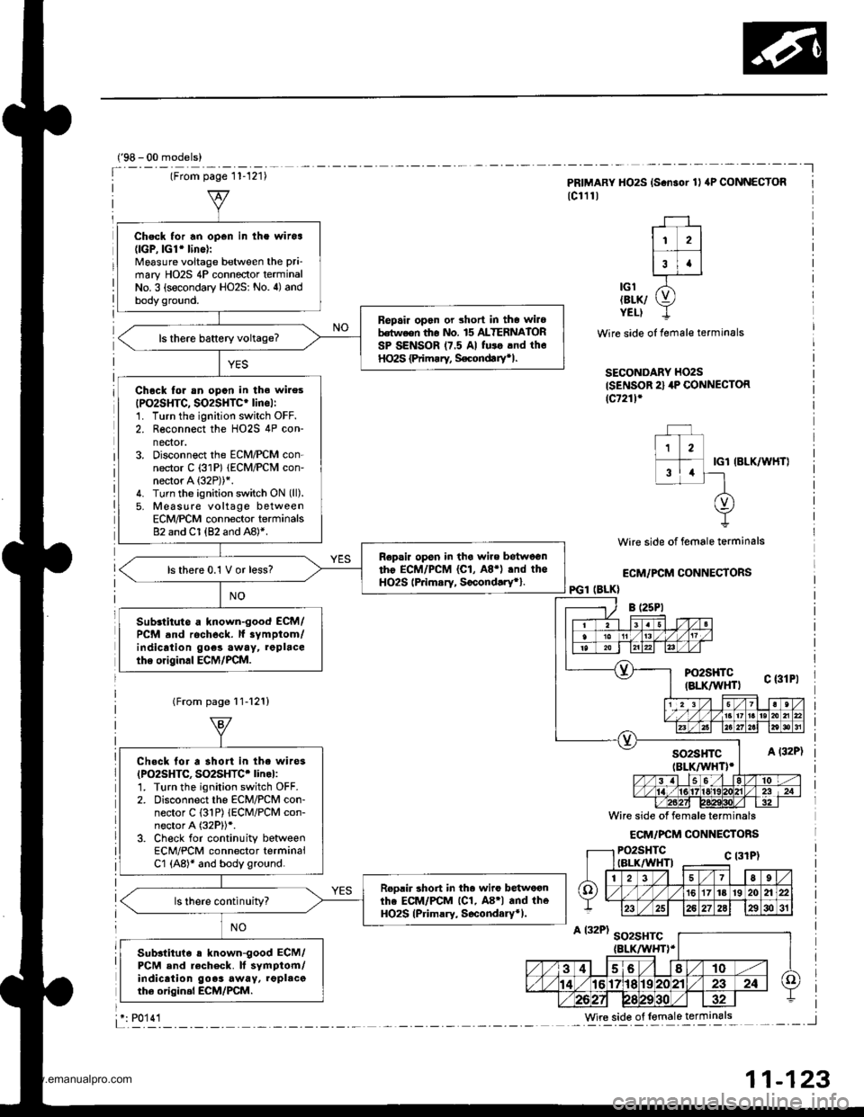
Check for an open in the witoa(lGP,lGl'lino):
Mgasure voitage between the pri-
mary HO2S 4P connector terminalNo. 3 (secondary HO2S: No. 4) andbody ground.
Bepair opan or short in tho wilobdtween th6 nlo. 15 ALTERNATORSP SENSOR 17.5 Al fu$ .nd th6HO2S {Primrry, S€condtrytl.
Chock lor sn opon in the wires
IPO2SHTC, SO2SHTC' lincl:1. Turn the ignition switch OFF.2. Reconnect the HO2S 4P con-nector.3. Disconnect the ECM/PCM con-nector C (31P) (ECM/PCM con-neaor A (32P))*.
4. Turn the ignition switch ON (ll).
5. Moasure voltage betweenECM/PCM connector terminals82 and Cl (82 and A8)*.
Repsir opsn in tha wire betweentho ECM/PCM (C1, A8.) .nd theHO2S lPrimsry, Socond.ry*}.ls there 0.1 V or less?
Sub.titute a known-good ECM/PCM and rocheck. lf iymptom/indicrtion goes away, repbcethe original ECM/PCM.
('98 - 00 models)
Wire side of female terminals
ECM/FCM CONNECTORS
IGl IBLK/WHT}
PRIMARY HO2S {S.n3or 1l aP CONNECTOR
lc111l
11 2l
r--T -l3t.lL-.IJ------J
lcl /5'tErK/ g,YELI I
Wire side of female terminals
SECONDARY HO2S
{SENSOR 2} 4P CONNECTOR(c7211'
PGl (BLK}
lFrom page 11-12'!)
Chock lor a short in the wi.es(PO2SHTC, SO2SHTC' linol:1. Turn the ignition switch OFF.2. Disconnect the EcM/PcM con-nector C {31P) lECM/PCM con-nector A (32P))*.
3. Check for continuity betweenECM/PCM connector terminalCl (A8)* and body ground.
Roolir 3hort in th. wiro betwoonthe ECM/PCM lC1, A8'l and theHO2S (Primary, S6condary*).ls there continuity?
Sub3tituie s known-good ECM/PCM and rech6ck. It symptom/indicaiion goes away. lgplacoth6 origin.l ECM/PCM.
Wire side of lemale terminals: P0'14'l
11-123
www.emanualpro.com
Page 334 of 1395
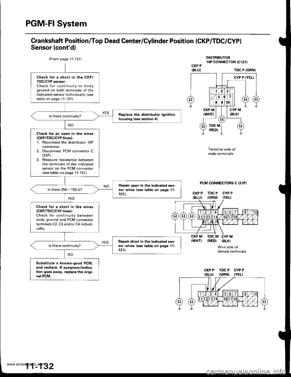
PGM-FI System
Grankshaft Position/Top Dead Center/Cylinder Position (CKP/TDC/CYPI
Sensor (cont'd)
DISTRIBUTOR10P CONNECTOR tCl2l)CKP P
IBLUITDC P {GRNI
PCM CONNECTORS C I31P)
CKP P TDC P CYP PIBLU) IGRNI IYEL}
Terminal side ofmale terminals
IREDI IBLK)
Wire side offemale terminals
{WHT)
{From page 1'1-131)
Check for a short in the CKP/TDC/CYP sensor:Check for continuity to bodyground on both terminals of theindicated sensor individually (see
table on page 1l 131).
R€plac€ the distributor ignitionhousing {see section 4}.ls there continuity?
Ch€ck fo. an open in the wires{CKP/TDC/CYP lines):'1. Reconnect the distributor 10Pconnector.2. Disconnect PCM connector C(31P).
3. Measure resistance betweenthe terminals of the indicatedsensor on the PCM connectorlseetable on page 1l 131).
Repair open in the indicated sen-sor wires {se6 table on page 11-131).ls there 350 - 700 0?
Check tor a short in the wires{CKP/TDC/CYP linesllCheck for continuity betweenbody ground and PCM connectorterminals C2, C3 and/or C4 individ-
R€Dair short in the indicatod sen-sor wires lsee table on page 11-13rI.ls there continuity?
Substitute a known-good PCM,and recheck. lf symptom/indica-tion goes away, r€place lhe origi-nal PCM.
CKP P TDC P CYP P
www.emanualpro.com
Page 335 of 1395
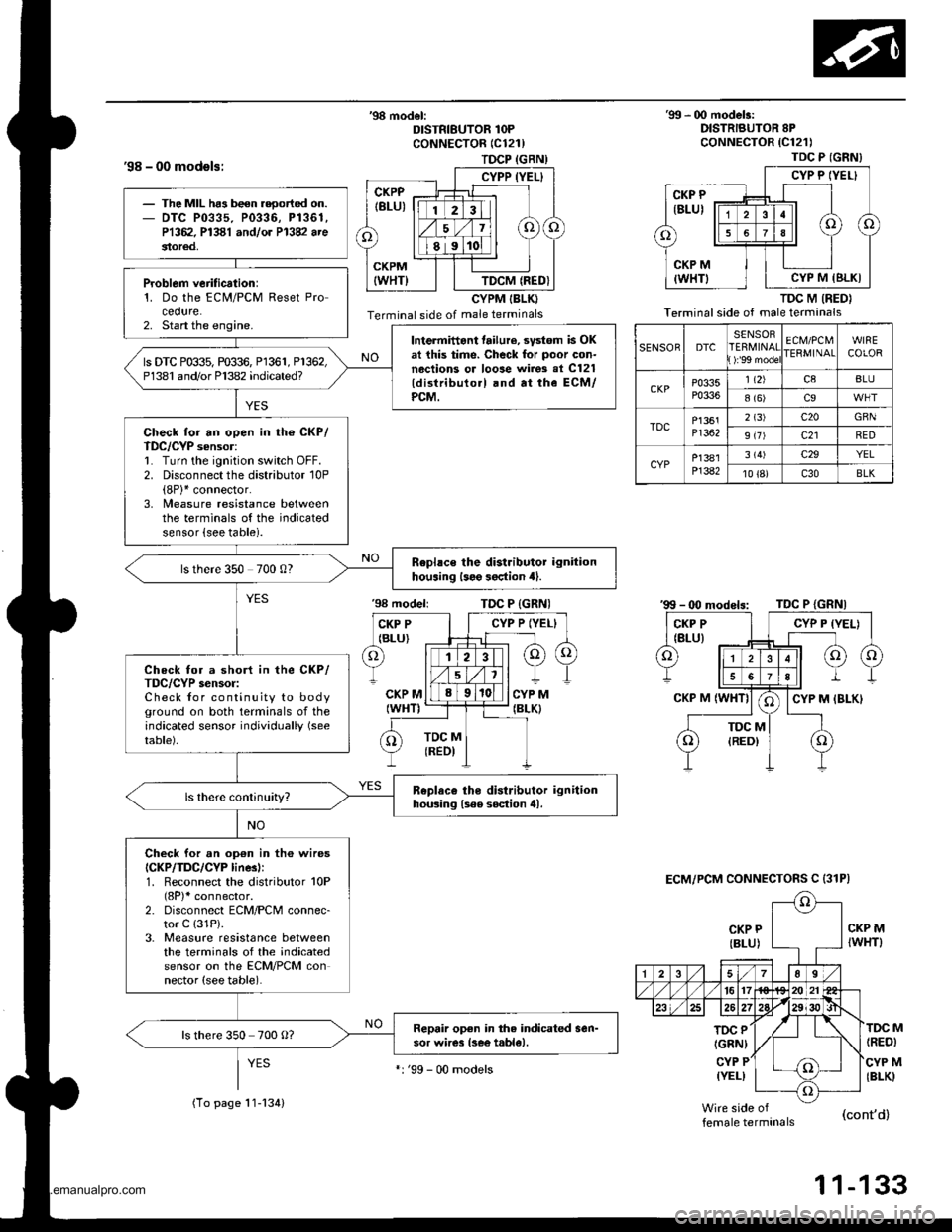
TDCP (GRN)
CYPP (YEL}
TDCM (REDI
'98 - 00 models:
'98 model:DISTRIBUTOR 1OPCoNNECTOR (C121)
CYPM IBLKI
Terminal side of male terminals
'99 - 00 modelr:DISTRIBUTOR 8PcoNNECTOR {C121)
TDC M (RED}
Terminal side of male terminals
CKP P
{BLU)
'98 modeliTDC P {GRNI
CKP MIWHT)
TOC P
IGRNI
CYP P(YEL)
(RED)
CYP M(BLKI
M
female terminals(cont'd)
1 1-133
TDC P (GNN}
CYP P IYEL}
CYP M IBLKI
SENSORDTCSENSORERMINAT):'99 mode
ECM/PCMIERMINAIWIRECOLOR
CKPP0335P0336
1 t2)c8BLU
8 (6)c9
TDCP1361Pl362
2 (3)c20GBN
9 (7)c21RED
CYPP]381P]382
3 (4)c29YEL
10 {8)c30BLK
ECM/PCM CONNECTOFS C {31P)
The MIL ha3 been reoorted on.DTC P0335. P0336, P1361,P1362. P1381 andlor P13V arestor€d,
Problem verification:1. Do the ECM/PCM Reset Procedure.2. Start the engine.Intermittant tailure, svstom is OKat this time. Check for poor con-nections or loose wirgs al C121{distributo.l .nd at the ECM/PCM.
ls DTC P0$5, m$6, Pl361, P1362,P1381 and/or Pl382 indicated?
Check for an open in th6 CKP/TDC/CYP sensor:1. Turn the ignition switch OFF.2. Disconnect the distributor 10P(8P)* connector.3, Measure resistance betweenthe terminals of the indicatedsensor {see table).
Rephce the distributor ignitionhouaing l3e9 3oction 4).ls there 350 700 0?
Check for a short in the CKP/TDC/CYP s€nsor:Check for continuity to bodyground on both terminals of theindicated sensor individually (see
table).
Replaco tho distributor ignitionhousing lsee soction tll.
Check for an op€n in th6 wiresICKP/TDC/CYP linesl:1. Reconnect the distributor 10P(8P)* connector.2. Disconnect ECM/PCM connec-tor C (31P).
3. Measure resistance betweenthe terminals of the indicatedsensor on the ECM/PCM connector (see table).
Repair open in the indicated sen-sor wires lsee t.ble).ls there 350 700 O?
(To page 11-134)
':'99 - 00 models
www.emanualpro.com
Page 337 of 1395
![HONDA CR-V 2000 RD1-RD3 / 1.G Workshop Manual
Vehicle Speed Sensor (VSSI
lPosoo-]-. |posol l-
97 modol:
The scan tool indicates Diagnostic Trouble Code {DTC} P0500*�or P0501*r: A range/perfor-
mance in the Vehicle Speed Sensor (VSS) circuit. HONDA CR-V 2000 RD1-RD3 / 1.G Workshop Manual
Vehicle Speed Sensor (VSSI
lPosoo-]-. |posol l-
97 modol:
The scan tool indicates Diagnostic Trouble Code {DTC} P0500*�or P0501*r: A range/perfor-
mance in the Vehicle Speed Sensor (VSS) circuit.](/manual-img/13/5778/w960_5778-336.png)
Vehicle Speed Sensor (VSSI
lPosoo-]-'. |posol l-'
'97 modol:
The scan tool indicates Diagnostic Trouble Code {DTC} P0500*'�or P0501*r: A range/perfor-
mance in the Vehicle Speed Sensor (VSS) circuit. * I ; A/T*2i Mfi
FCM CONNECTORS
A t32Pl
LG1(BRN/BLK)
NOTE: Do not use the engine to turn thofront wheels with th6 rear wheels on theground. The 4WD system will engage andthe vehicle will suddenlv Iurch forward.
Wire side ot female terminals
LGl
{BRN/BLKI
(cont'd)
11-135
The MIL hes boen roported on.DTC m501 is 3tor€d.
Problom verificetion:1. Test'drive the vohicle.2. Check the vehicle speed withthe scan tool,
lntormittent tailure, rystom b OKat thia timo. Chock tor poor con-nection3 or 10o3o wires rt C129lvss) .nd rr rhe Pcfr4,
ls the correct speed indicated?
Chock for an open in tho PiCM:1. Turn the ignition switch OFF.2. Block the rear wheels and setthe parking brake.3. Jack up the lront of the vehicleand support it with saletystands.4. Turn the ignition switch ON (ll).
5. Elock the right front wheel andslowly rotate the left trontwheel by hand.6. Measure voltage betweenPCM connector terminals C18and A9.
Substitulc a known-good PCMand .och6ck. It symptom/indicd.tion go.a away, .cplaco tho origi-nel FCM.
Doesthe voltage pulse 0 Vand 5 V or battery voltage?
Check for a .hort in the PCM:L Turn the ignition switch OFF.2. Disconnect the PCM con'nector C (31P).
3. Turn the ignition switch ON (ll).
4. Elock the right front wheeland slowly rotate the left front
5. Measure vohage between PCMconnector terminals C18 andA9.
Substituto e known-good PCMand rochock. f rymptom/indica-tion goos rwry, roplsc. tho origi-nalFCM.
Doesthe voltage pulse 0 Vand 5 V or battery voltage?
- Repair short in the wirebetween the PCM lC18l,cruise control unit, speodo-meter, and VSS,- Repair opon in the wirebetween the PCM {C181 .ndrhe vss.- f wire is OK. tost lho VSS l3oosoction 231.
www.emanualpro.com
Page 343 of 1395
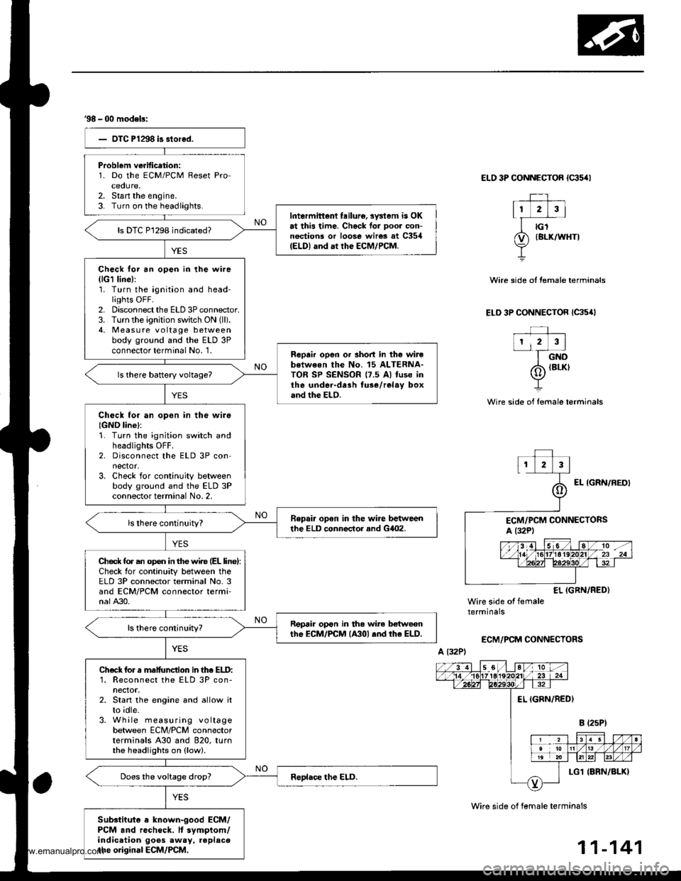
38 - 00 modeb:
Problem verification:1. Do the ECM/PCM Reset Proceoure.2. Stan the engine.3- Turn on the headlights.Intermittent feilure, sysl.m is OKat this time. Check for ooor con-nections or loose wires at C354(ELDI and at the ECM/PCM.
ls DTC P1298 indicated?
Check lor an open in the wire(lG1 line):'1. Turn the ignition and head-lights OFF.2. Disconnect the ELD 3P connector.3. Turn the ignition switch ON (ll).
4, Measu re voltage betweenbody ground and the ELD 3Pconnector terminal No. '1.Reprir open or short in th6 wirebotweon the No. 15 ALTERNA-TOR SP SENSOR {7.5 Al fuse inthe under-drah fuse/relay boxand the ELD.
Check tor an opon in tho wire{GND line}:1. Turn the ignition switch andheadlights OFF.2. Disconnect the ELD 3P connector.3. Check for continuity betweenbody ground and the ELD 3Pconnector terminal No. 2,
Repair opon in the wire betweenthe ELD conneclor and GilO2.
Ched( fo. an op€n in the wir€ (EL linel:Check for continuity between theELD 3P connector terminal No. 3and ECM/PCM connector termi-nalA30.
Repair op€n in tha wile botwecnthe EcM/PCM lA30l .nd rhe ELD.
Check for s malfunction in lhe ELD:1. Reconnect the ELD 3P con-nector.2. Start the engine and allow itto idle.3. While measuring voltagebetween ECM/PCM connectorterminals A30 and 820, turnthe headlights on (low).
Substiiute a known-good ECM/PCM and recheck. It symptom/indication goos away, replacethe original ECM/PCM.
ELO 3P CONNECTOR {c35/rl
Wire side of female terminals
Wire side of female terminals
Wire side ot temale terminals
ELD 3P CONNECTOR {C35,lt
EL IGRN/RED}Wire side of femaletermrnars
ECM/PCM CONNECTORS
A l32P)
11-141
www.emanualpro.com
Page 346 of 1395
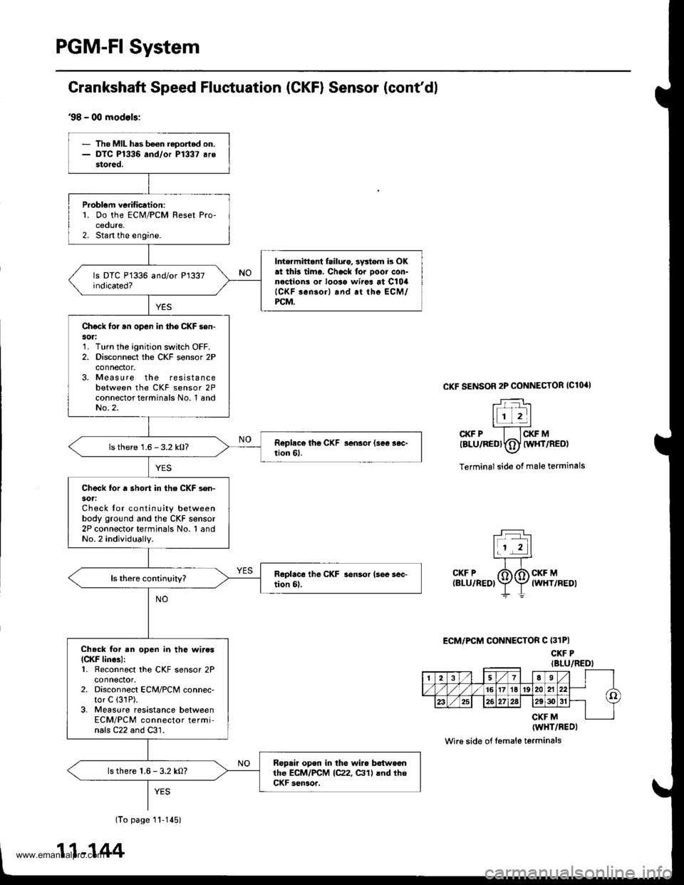
PGM-FI System
Grankshaft Speed Fluetuation (CKFI Sensor (cont'dl
.98 - 00 modols:
CKF SENSOR 2P CONNECTOR IClO'I
r-:-i-_ltr_- |l1 2ll,,-'CKF P I ICKF MtsLuneotTOl wlrrneo)\7
Terminal side of male terminals
r:l
t! El
.KFP XA"*."talu rneor \:f
f rwxvneor
ECM/PCM CONNECTOR C (31P)
CKF PIBLU/REDI
CKF M(WHT/BEOI
Wi16 side of l6male terminals
1278__l
-lI(o
T
161716't9202122
,/ 2s262728293()3l
M
- The MIL has boon reported on.- DTC P1336 and/or P1337 arestored.
ProblGm verification:1. Do the ECM/PCM Reset Pro-cedure,2. Stan the engine.
Inte.mittant failuro, 3y*om b OKat thb tima. Chack lor ooor con-nections or looso wirea at C10a{CKF sensorl and.t the ECM/PCM,
Chgck forun open in tho CKF son-sori1. Turn the ignition switch OFF.2. Disconnect the CKF sensor 2Pconnector.3. Measure the resistancebetween the CKF sensor 2Pconnector terminals No. 1 andNo.2.
lsthere 1.6 - 3.2 kO?
Check for a short in the CKF sen-
Check lor continuity betweenbody ground and the CKF sensor2P connector terminals No. 1 andNo.2 individually.
Check for an open in the wiresICKF linca):1. Feconnect the CKF sensor 2Pconnector.2. Disconnect ECM/PCM connec-tor C (31P).
3. Measure resistance betweenECM/PCM connector termi'nals C22 and C31.
Repair opon in the wir6 botwoonthe ECM/PCM 1C22, glll lnd th6CKF s6n3or.
ls there 1.6 - 3.2 kO?
(To page 11'1451
11-144
www.emanualpro.com