Page 151 of 1395
Flywheel and Drive Plate
Replacement
Manual Transmission:
Remove the eight flywheel bolts, then separate the fly-
wheel from the crankshaft flange. After installation, tight-
en the bolts in the sequence shown.
ENGINEBLOCK
12 x 1.0 mm103 N.m 110.5 kgf.m,76 lbf.ft)
Automatic Transmission:
Remove the eight drive plate bolts, then separate the
drive plate from the crankshaft flange. After installation,
tighten the bolts in the sequence shown.
RING GEARInspect ring gearteeth for wear or damage,
RI G GEAR HOTDER07LAB - PV001|X)
12 x 1.0 mm7a N.m(7.5 kgt.m,5a lbf.ftl
/ AzXi{'jA\Ao
7-5,
www.emanualpro.com
Page 152 of 1395
Connecting Rod and Crankshaft
End Play
1. Measure the connecting rod end play with a feeler
gauge.
Connecting Rod End Play:
Stsndard (Nsw): 0.15 - 0.30 mm
{0.006 - 0.012 in)
Service Limit: 0./t0 mm 10.016 in)
2. lf the connecting rod end play is out-of-tolerance,
install a new connecting rod.
lf it is still out-of-tolerance, replace the crankshaft
{see pages 7-9 and 7-20).
7-6
3. Push the crankshaft firmly away from the dial indi-
cator, and zero the dial against the end of the
crankshaft. Then pull the crankshaft firmly back
toward the indicator; the dial reading should not
exceed the service limit.
Crankshaft End Play:
Stand.rd (New): 0.10 - 0,35 mm(0.004 - 0.014 inl
Service Limit: 0.45 mm (0.018 inl
4. lf end play is excessive, inspect the thrust washers
and thrust surface on the crankshaft. Reolace oans as
necessary. Thrust washer thickness is fixed and
must not be changed either by grinding or shim-
mrng.
SCREWORIVER
www.emanualpro.com
Page 153 of 1395
Main Bearings
2.
3.
1.
4.
Clearance
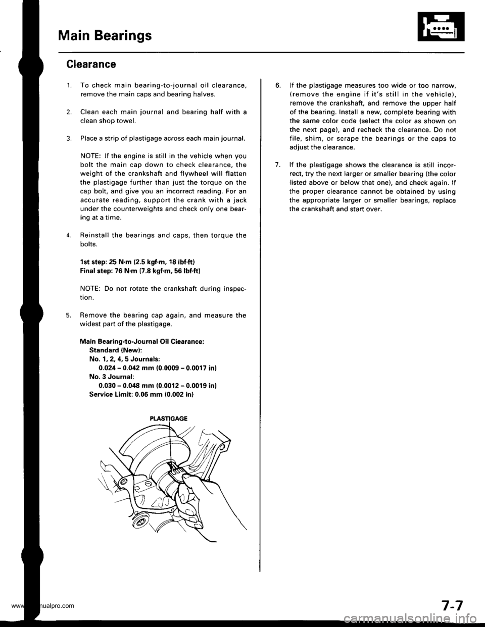
To check main bearing-to-journal oil clearance,
remove the main caps and bearing halves.
Clean each main journal and bearing half with a
clean shop towel.
Place a strip of plastigage across each main journal.
NOTE: lf the engine is still in the vehicle when you
bolt the main cap down to check clearance, the
weight of the crankshaft and flywheel will flatten
the plastigage further than just the torque on the
cap bolt, and give you an incorrect reading. For an
accurale reading, support the crank with a jack
under the counterweights and check only one bear-
Ing aI a Irme.
Reinstall the bearings and caps, then torque the
bolts,
1st step:25 N'm (2.5 kgf.m, 18lbf.ft)
Final siep: 76 N'm 17.8 kgl.m, 56 lbf.ftl
NOTE: Do not rotate the crankshaft during inspec-
tron.
Remove the bearing cap again, and measure the
widest part of the plastigage.
Main Bearing.to.Journal Oil Clearance:
Stand8.d {New):
No. 1,2,4,5 Journsls:
0.02i1- 0.0i12 mm (0.0009 - 0.0017 inl
No. 3 Journal:
0.030 - 0.0i18 mm (0.0012 - 0.0019 inl
Service Limit: 0.06 mm 10.002 in)
lf the plastigage measures too wide or too narrow,(remove the engine if it's still in the vehicle),
remove the crankshaft, and remove the upper half
of the bearing. Install a new, complete bearing with
the same color code (select the color as shown on
the next page). and recheck the clearance, Do not
file, shim, or scrape the bearings or the caps to
adjust the clearance.
lf the plastjgage shows the clearance is still incor-
rect, try the ne)d larger or smaller bearing {the color
listed above or below that one), and check again. lf
the proper clearance cannot be obtained by using
the appropriate larger or smaller bearings, replace
the crankshaft and start over.
7.
7-7
www.emanualpro.com
Page 154 of 1395
Main BearingsConnecting Rod Bearings
Selection
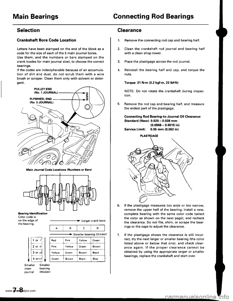
Crankshaft Bore Code Location
Letters have been stamDed on the end of the block as a
code Jor the size of each of the 5 main journal bores.
Use them, and the numbers or bars stamped on the
crank (codes for main journal size), to choose the correct
beanngs.
lf the codes are indecipherable because of an accumula-
tion of dirt and dust. do not scrub them with a wire
brush or sc.aper. Clean them only with solvent or deter-
gent.
Main Journ.l Cod. Locrtions lNumbcB oi Bar3l
Bearing ld.ntif icrtionColor code ison the edge ofthe bearing.
7-8
IcD
"""""""" Smallerbearing(rhicker)
Green
Green
ElaclAlue
Clearance
Remove the connecting rod cap and bearing half.
Clean the crankshaft rod journal and bearing half
with a clean shop towel.
Place the plastigage across the rod journal.
Reinstall the bearing half and cap, and torque the
nuts.
1.
7.
Torqus: 31 N.m (3.2 kgf.m. 23 lbf.ft)
NOTE: Do not rotate the crankshaft during inspec-
tion.
Remove the rod cap and bearing half, and measure
the widest part of the plastigage.
Connesting Rod Bearing-to-Journal Oil Clearancc:
Standard {Newl: 0.020 - 0.038 mm
{0.0008 - 0.0015 in)
Service Limit: 0.05 mm {0.002 inl
lf the plastigage measures too wide or too narrow,
remove the upper half of the bearing, install a new.
complete bearing with the same color code {select
the color as shown on the next page), and recheck
the clearance. Do not file, shim, or sc.ape the bear-
ings or the caps to adjust the clearance.
lf the plastigage shows the clearance is still incor
rect, try the next larger or smaller bearing {the color
listed above or below that one). and check clear-
ance again. lf the proper clearance cannot be
obtained by using the appropriate larger or smaller
bearings. replace the crankshaft and start over.
PLASTIGAGE
www.emanualpro.com
Page 155 of 1395
Pistons and
Crankshaft
Selection
Connecting Rod Code Location
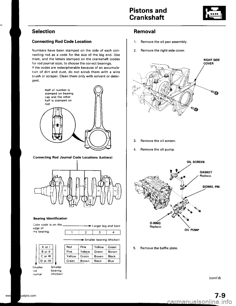
Numbers have been stamped on the side of each con-
necting rod as a code for the size of the big end. Use
lhem, and the letters stamped on the crankshaft (codes
for rod journal size), to choose the correct bearings.
lf the codes are indeciDherable because of an accumula-
tion of dirt and dust, do not scrub them with a wire
brush or scraper. Clean them only with solvent or deter-
gent.
8€aring ldentif ication
aolor code is on theedge oltne Deanng.
Larger big end bore
---------------r. sma er bearino {thicker)
RedPinkGreen
PinkGreenBrown
GreenBrownBlack
GreenBrownElackBlue
Half of number isstamped on beanngcap and the othelhalf is stamped onrod.
Connecting Rod Journal Code Locations {Lettersl
llAort ll
llBo'll ll
llcotrll ll
I l-.. ilril It-lSmaller'odSmallerbeanng(thicker)
234
Removal
Remove the oil pan assembly.
Remove the right side cover.
1.
Remove the oil screen.
Remove the oil pump.
OIL SCREEN
(cont'd)
7-9
OIL PUMP
5. Remove the baffle plate.
www.emanualpro.com
Page 156 of 1395
Pistons and Crankshaft
Removal (cont'dl
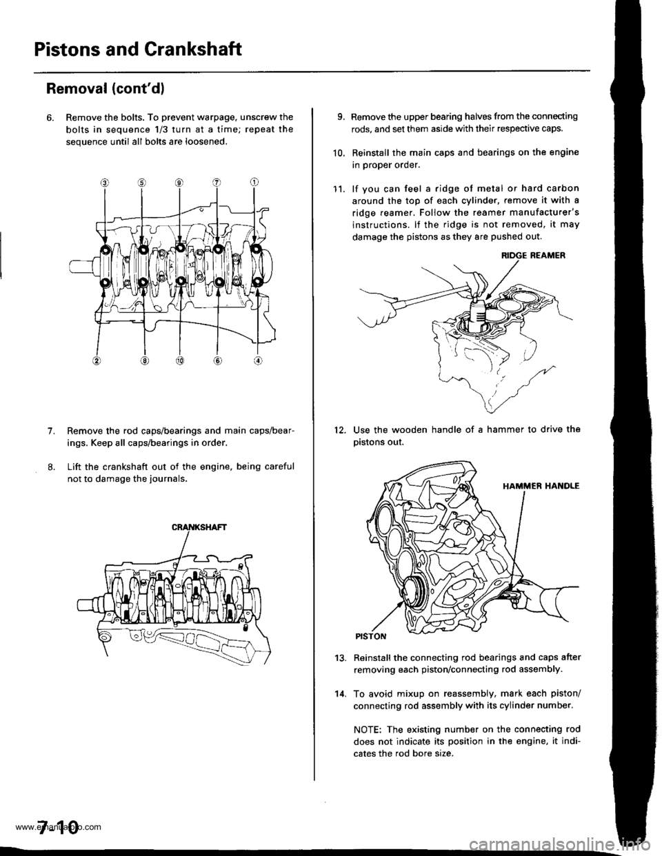
6. Remove the bolts. To prevent warpage, unscrew the
bolts in sequence 1/3 turn at a time; repeat the
sequence until all bolts are loosened.
Remove the rod caps/bearings and main caps/bear-
ings, Keep all caps/bearings in order
Lift the crankshaft out of the engine. being careful
not to damage the journals.
7.
7-10
9.
10.
Remove the upper bearing halves from the connecting
rods, and set them aside with their respective caps.
Reinstall the main caps and bearings on the engine
in proper order.
lf you can feel a ridge of metal or hard carbon
around the top of each cvlinder, remove it with a
ridge reamer. Follow the reamer manufacturer's
instructions. lf the ridge is not removed, it may
damage the pistons as they 8re pushed out.
12.
11.
14.
Use the wooden handle of a hammer to drive the
pistons out.
13.Reinstall the connecting rod bearings and caps after
removing each piston/connecting rod assembly.
To avoid mixup on reassembly, mark each piston/
connecting rod assembly with its cylinder number.
NOTE: The existing number on the connecting rod
does not indicate its position in the engine, it indi-
cates the rod bore size.
www.emanualpro.com
Page 157 of 1395
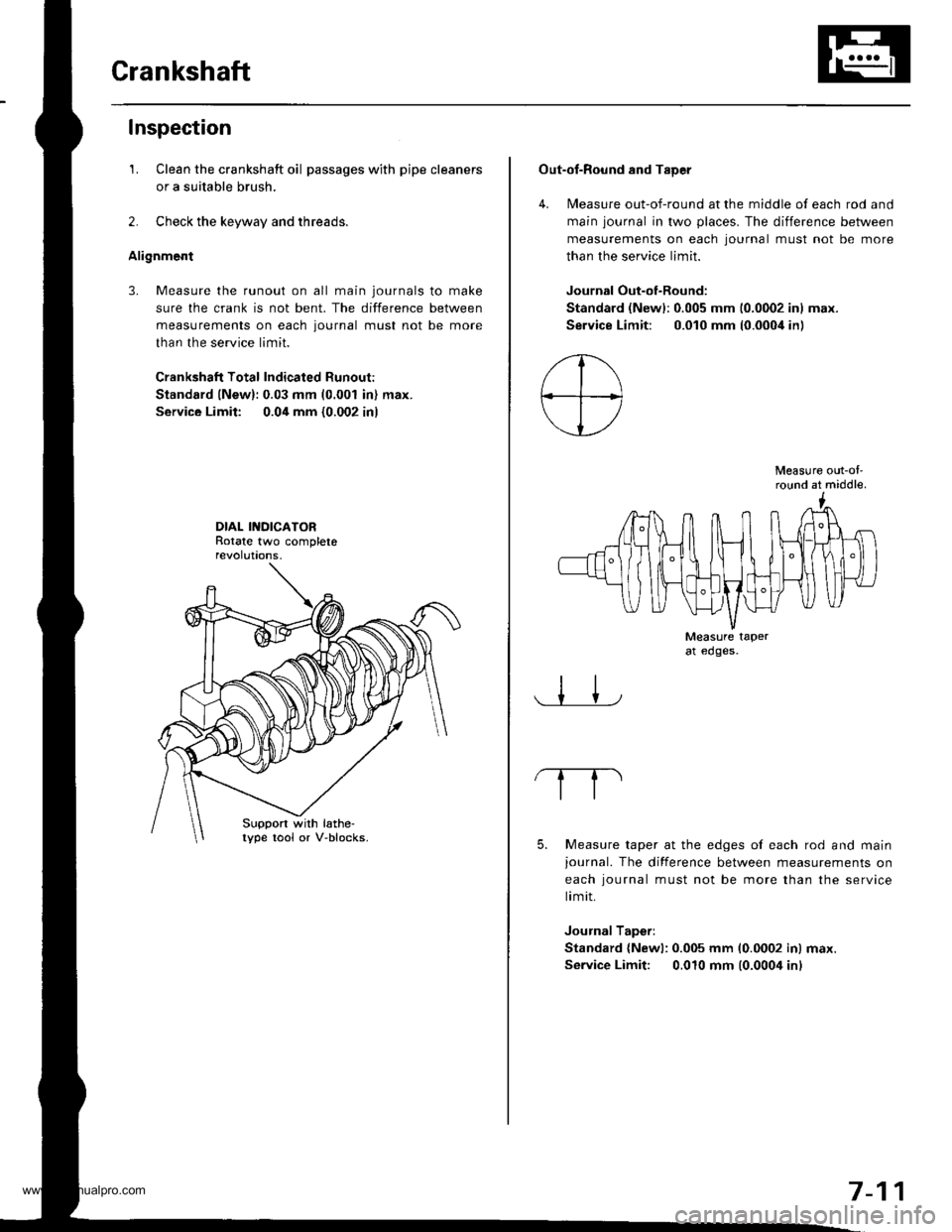
Crankshaft
Inspection
1. Clean the crankshaft oil passages with pipe cleaners
or a suitable brush.
2. Check the keyway and threads.
Alignment
3. Measure the runout on all main journals to make
sure the crank is not bent. The difference between
measurements on each journal must not be more
than the service limit.
Crankshaft Total Indicated Runout:
Standard lNew):0.03 mm (0.001 in) max.
Service Limit: 0.04 mm {0.002 in)
DIAL INDICATORRotate two completerevolut|ons.
Suppon with lathe-lype tool or V-blocks.
Out-of-Round and TaDer
4. Measure out-of-round at the middle of each rod and
main journal in two places. The difference between
measurements on each lournal must not be more
than the service limit.
Journal Out-of-Round:
Standard (Newl:0.005 mm 10.0002 inl max.
Service Limit: 0.010 mm (0.000i1in)
Measure out-ol'round at middle.
Measure taperat edges.
5. Measure taper at the edges of each rod and mainjournal. The difference between measurements on
each iournal must not be more than the service
limit.
Journal Taperi
Standard {Newl: 0.005 mm 10.0002 inl max.
Service Limit: 0.010 mm (0.0004 inl
7-11
www.emanualpro.com
Page 165 of 1395
Crankshaft Oil Seal
Rotate the rings in their grooves to make sure they
do not bind.
Position the ring end gaps as shownl
SECOND RING GAP
Appror.90"
DO NOT position any ring gap
at piston thrust surfaces,
OIL RINGGAPAppror.90'TOP RI.IIG GAPSPACER GAP
DO NOT position any ring gap
in line with the piston pin hole.OIL RING GAP
1.
lnstallation
The seal mating surface on the block should be dry
Apply a light coat of oil to the crankshaft and to the
lip of the seal.
Drive the crankshaft oil seal squarely into the right
sroe cover.
DRIVER
lnstall seal with thepart number sidefacing out.
Confirm that the clearance is equal all the way around
with a feeler gauge.
Clearance:0.5 - 0.8 mm {0.02 - 0.03 inl
NOTE| Refer to pages 7 23 and 8-10 for installation
of the oil oumD side crankshait oil seal.
0.5-0.8 mm{O.02 0.03 in)
7-19
www.emanualpro.com