2000 HONDA CR-V Oil pan
[x] Cancel search: Oil panPage 451 of 1395
Transmission Assembly
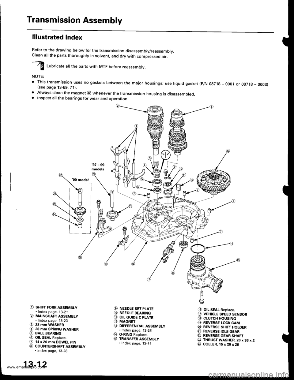
lllustrated Index
Refer to the drawing below for the transmission disassembly/reassembly.Clean all the pans thoroughly in solvent, and drv with comoressed air.
I LuUri""r" utt the parts with MTF before reassembly.
NOTE:
t This transmission uses no gaskets between the major housings; use liquid gasket (p/N 0g718 - 0001 or oE7l8 - 0003)(see page 13-69, 71).. Always clean the magnet @ whenever the transmissjon housing is disassembled.. Inspect all the bearings for wear and operation.
C) sHrFr FoRK ASSEMBLY.Index page, l3-21(a MAINSHAFT ASSEMBLY.Index page, 13-23(9 28 mm WASHER€) 28 mm SPRTNG WASHERO BALL BEARINGa6) OIL SEAL ReDlace.(D 14 x 20 mm DOWEL ptN
G) couNTERSHAFT ASSEMBLY.lndex page, 13-28
NEEDLE SET PLATENEEDLE BEARINGOIL GUIOE C PLATEMAGNETDIFFERENTIAL ASSEMBLY.lndex page, 13-38O-nlNG Beplace.TRANSFER ASSEMBLY.Index page, '13,44
OIL SEAL Replace.VEHICLE SPEED SENSORCLUTCH HOUSINGREVERSE LOCK CAMREVEESE SHIFT HOLDERREVERSE IDLE GEARREVERSE GEAR SHAFTTHRUST WASHER,20 x 36 x 2COLLER, 15 x 20 x 20
aol
@o@@
(D
i9
@@@(9
@@@e3@
13-12
www.emanualpro.com
Page 487 of 1395
Transfer Assembly
Disassembly (cont'd)
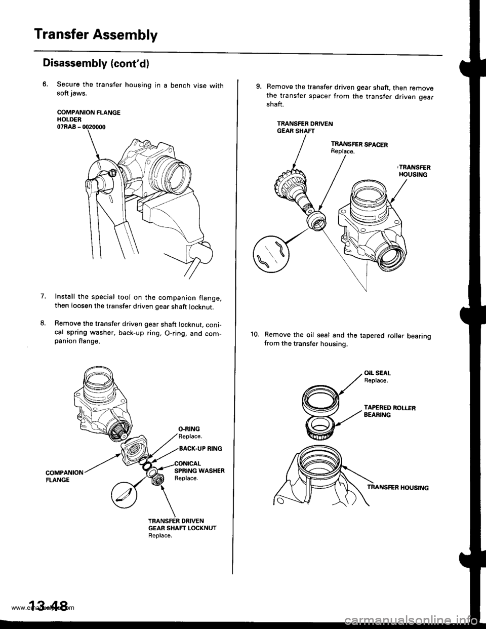
Secure the transfer housing in a bench vise withsoft jaws.
COMPANION FLANGEHOLDER07RAA -
Install the special tool on the companion flange,then loosen the transfer driven gear shaft locknut.
Remove the transfer driven gear shaft locknut, coni-cal spring washer, back-up ring, O-ring, and com-psnion flange.
7.
TRANSFER DRIVENGEAR SHAFT LOCKNUTReolace,
13-48
9. Remove the transfer driven gear shaft, then removethe transfer spacer from the transfer driven gearshaft.
TRANSFER ORIVENGEAR SHAFT
Remove the oil seal and the tapered roller bearingfrom the transfer housing,
OIL SEALReplace.
TAPEREO ROLIIRAEARING
TRANSFER HOUSING
www.emanualpro.com
Page 492 of 1395
Transter Gear Backlash Inspection and Transfer Gear
Tooth Contaqt Inspection
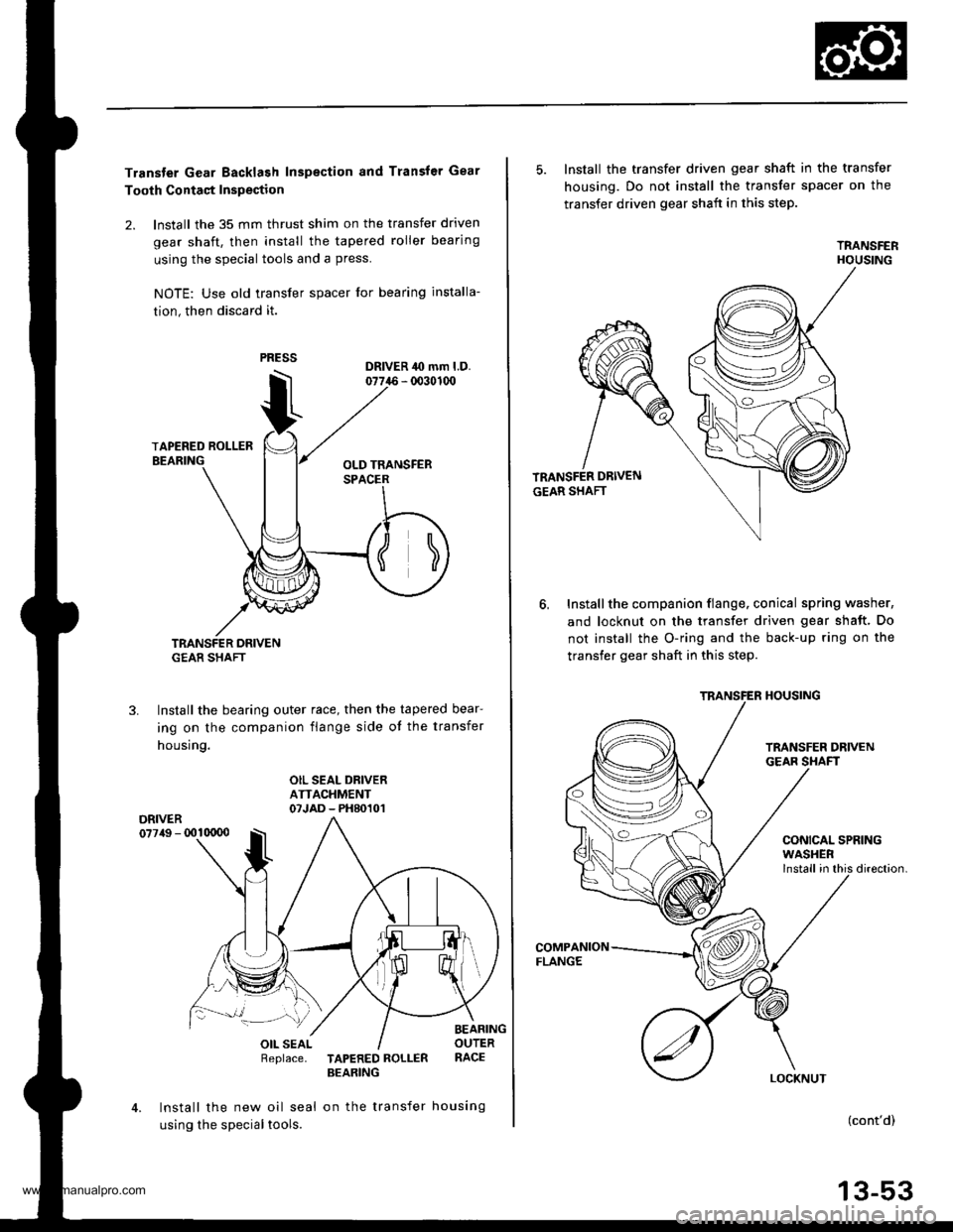
2. lnstall the 35 mm thrust shim on the transfer driven
gear shaft, then install the tapered roller bearing
using the special tools and a press.
NOTE: Use old lransfer spacer for bearing installa-
tion, then discard it.
TRANSFER DRIVENG€AR SHAFT
Install the bearing outer race, then the tapered bear-
ing on the companion flange side ot the transfer
housing.
3.
OIL SEAL DRIVERATTACHMENT07JAD - PH80101DRIVER077/tg - 001qt00
Replace.TAPERED ROLLERBEARING
Install the new oil seal on the transfer housing
using the special tools.
5. Install the transfer driven gear shaft in the transfer
housing. Do not install the transfer spacer on the
transfer driven gear shaft in this step.
TRANSFERHOUSING
Installthe companion flange. conical spring washer,
and locknut on the transfer driven gear shaft. Do
not install the O-ring and the back-up ring on the
transfer gear shaft in this step.
6,
COMPANIONFLANGE
CONICAL SPRING
direction.
(cont'd)
13-53
TRANSFER HOUSING
WASHER
www.emanualpro.com
Page 518 of 1395
Ref. No.
^tl)
@
*rar
@
@
,-o
@
o
@
@
@
@
@.--@
@
@
@
@
@
@
@
@
@
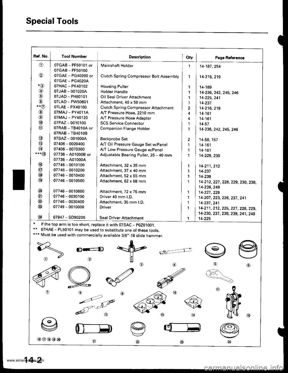
Tool NumberDescriptionOty I Pago Referonc€
Mainshaft Holder
Clutch Spring Compressor Bolt Assembly
Housing Puller
Holder Handle
Oil Seal Driver Aftachment
Attachment, 40 x 50 mm
Clutch Spring Compressor Attachment
Ay'T Pressure Hose, 2210 mm
IVT Pressure Hose Adapter
SCS Service Connector
Companion Flange Holder
Backprobe Set
lVT Oil Pressure Gauge Set w/Panel
A,/T Low Pressure Gauge w/Panel
Adjustable Bearing Puller, 25 - 40 mm
Anachment, 32 x 35 mm
Attachment, 37 x 40 mm
Attachment. 52 x 55 mm
Attachment. 62 x 68 mm
Attachment, 72 x 75 mm
Driver 40 mm l.D.
Attachment, 35 mm LD.
Driver
07GAB - PF50101 or
07GAB - PF50100
07GAE - PG40200 or
OTGAE _ PG4O2OA
07HAC - PK40102
07JAB - 001020A
07JAD - PH80101
07LAD - PW50601
07LAE - PX40100
OTMAJ - PY4O114
07MAJ - PY40120
07 PAZ - 0010100
07RAB - TB4010A or
07RAB.TB40lOB
07sAz - 001000A
07406 - 0020400
07406 - 0070300
07736 - 4010008 or
07736 - A010004
07746 - 0010100
07746 - 0010200
07746 - 0010400
07746 - 0010500
07746 - 0010600
07746 - 0030100
07746 - 0030400
07749 - 0010000
07947 - SD90200Seal Driver Aftachment
1
1
1
1,l
1
I
2
1'l
1
I
1
1
1
1
1
1
I
1
14-181 , 254
14-216,219
14-189't4-236,242,245,246
't 4-225, 241
14-237
14-216,2't9
14-161
14- 161
14-57
14-236,242,245,246
14-58, 157
14-161
14-161'14-229,230
14-211, 2't2
14-231
14-239
14-212, 227 , 228,229, 230, 238,
14-239, 249
14-221 ,229't 4-207 , 223,226, 237 , 241
14-237,241
1 +21 1, 2't2, 225, 227, 228, 229,
14-230, 237 , 238, 239, 24't, 249't4-225
lf the top arm is too short, replace it with 07SAC - pOZ01OO1.
07HAE - PL50101 may be used to substitute one of these tools.Must be used with commercially available 3/8"-16 slide hammer.
E----G
@@@@@
@
tvj
'
@@@)
14-2
www.emanualpro.com
Page 677 of 1395

Pressure Testing
Changing
NOTE: Keep all foreign particles out of the transmis-
sion.
1. Bring the transmission up to operating temperature
(the radiator fan comes on) by driving the vehicle.
Park the vehicle on level ground. turn the engane
off. then remove the drain Plug.
NOTE: lf a cooler flusher is to be used, see page
14-264 and 14-265.
TRANSMISSIONEND COVER
DRAIN18 x 1.5 mmSEALING WASHEBReplace.49 N.m {5.0 kgt.m, 36 lbf.tl)
Reinstall the drain plug with a new sealing washer,
then refill the transmission with the recommended
fluid to the uDper mark on the dipstick. Always use
Genuine Honda Premium Formula Automatic
Transmission Fluid (ATF) Using a non-Honda ATF
can affect shift quality.
Automatic Transmission Fluid Capacity:
4WD;
2.9 { (3.1 US qt. 2.6 lmp qt) 8t change
5.8 ? {7.2 US $, 6.0 lmp qt} at ovethaul
2WD:
2.7 | l2.S US qt,2.1lmp qtl ai change
5.9 ? {6.2 US $, 5.2 lmp qtl at ovolhaul
2.
a
a
1.
Wlrile testing, be careful of the rotaling wheols.
Mako sure lifts, iacks, and safety stands ar€ placed
properly (see scction 11.
Before testing, be sure the transmission fluid is
filled to the proPer level.
4WD:
Raise the vehicle (see section 11.
2WD:
Raise the front of the vehicle, and make sure it is
securely supported. Set the parking brake, and block
both rear wheels securely.
Allow all four wheels {4WD) or front wheels (2wD}
to rotate freely.
Warm up the engine (the radiator fan comes on),
then stop it and connect the tachometer.
Connect the oil pressure gauges to each inspection
hole securely, and do not allow dust or other foreign
particles to enter the inspection holes.
TOROUE: 18 N'm ll.8 kgf'm, 13 lbf'ft)
5.
A/T PRESSURE HOS€,2210 mm07MAJ - PYiOllA
{4 Requircd}
,4'/"' ,a
W'
A/T PRESSURE HOSEADAPTER07MAJ - PYt0120(il Rcquiledl
6. Measure the following Pressure:. Line Pressure ..........,14-162
. 1st. 1st-hold Clutch Pressure .............'. 14-162
. 2nd,3rd and 4th Clutch Pressure .......... 14-163
7. Install new sealing washers and the sealing bolts in
the inspection holes, and tighten to the specified
toroue.
(cont'd)
A/T OIL PRESSUREGAUGE SET W/PANEL07{06 - 0020400
/4\\-J-- (
+..\.-.\-'-\
A/T LOW PBESSUREGAUGE w/PANEL07406 - 0070300
TOROUE: 18 N'm 11.8 kgf'm, 13 lbf'ft)
14-161
www.emanualpro.com
Page 680 of 1395

Transfer
4.
Inspection
@E Mako suro lifts, jacks, and safety standsare placod properly lsoe section t).
1. Raise the front of the vehicle, and make sure it issupported securely.
2. Set the parking brake, and block both rear wheelssecurely.
Shift to E position.
Make a reference mark across the propeller shaftand the transfer assembly flanges.
Separate the propeller shaft from the transferassembly.
8 x 1.25 mm32 N.m 13.3 kgl,m,24 lbf.ftlReplace.
14-164
\
6. Set a dial indicator on the transfer assembly flange.then measure the transfer gear backlash.
STANDARD: 0.06 - 0.16 mm (0.002 - 0.006 inl
7. lf the measurement is out of standard, remove thetransfer assembly and adjust transfer gear backlash{see page '14-232 thru 14-2491.
8. Check for fluid leaks between the mating faces oftransfer cover A and cover B.
9. lf there is a fluid leak, remove the cover, and reDlacethe O-ring.
'10. Check for fluid leaks between the mating face of thetransfer assembly and transmission.
11. lf there is a fluid l€ak, remove the transf€r assem-bly, and replace the O-ring,
12. Check the transfer oil seal for damage and fluidle8ks.
13, lf oil seal replacement is required. remove the trans-fer assembly, replace the oil seal, and adjust thetotal starting torque (see page 1+232 thtu ]'4-249||.
NOTE: Do not replace the oil seal with the transferassembly on the transmission.
COMPANION FLANGE
www.emanualpro.com
Page 699 of 1395

oatl,6
@!.,
ao6l
@o@@@@@o@@@)@@@@@@@@@@)
@@@@)@@@@@@@
REVERSE IDLER GEAR SHAFT,/HOLDERNEEOLE BEARINGTRANSMISSION HOUSINGTRANSMISSION HOUSING OIL SEAL R€place.SET RING,80 mm Selective part
REVERSE GEAR COLLARCOUNTERSHAFT REVERSE GEARNEEDLE BEARINGLOCK WASHER Replace.REVERSE SHIFT FORKREVERSE SELECTORREVERSE SELECTOR HUBCOUNTERSHAFT 4TH GEARNEEDLE BEARINGDISTANCE COLLAR,28 mm Selective pan
COUNTERSIIAFT 2ND GEARTHRUST NEEDLE BEARINGCOUNTERSHAFT 3RD GEARNEEDLE AEARINGCOUNTERSHAFT 3RD GEAR COLLARTHRUST NEEOLE BEARINGSPLINEO WASHER3RD CLUTCH ASSEMBLYO-RINGS Replace.COUNTERSHAFTSHIFT CONTROL SOLENOID COVERHARNESS CLAMP BRACKETSHIFT CONTROL SOLENOID VALVE A/B ASSEMBLYHARNESS CLAMP BRACKETSHIFT CONTROL SOLENOID VALVE FILTER/GASKETReplace.SNAP RINGTHRUST WASHERTHRUST NEEDLE BEARINGMAINSHAF ,ITH GEARNEEDLE BEARINGSTHRUST NEEDLE BEARINGMAINSHAFT 4TH GEAR COLLAR2ND/4TH CLUTCH ASSEMBLYO-RINGS ReDlace.THRUST WASHER,36.5 x 55 mm Selective part
THRUST NEEDLE BEARING
MAINSHAFT 2ND GEARNEEDLE BEARINGTHRUST NEEOLE BEARINGMAINSHAFTSEALING RINGS,35 mmSEALING RING. 29 mmNEEDLE BEARINGSET RINGlST-HOLD CLUTCH ASSEMSLYO-RINGS Replace.THRUST WASHERTHRUST NEEDLE BEARINGNEEDLE BEARINGSUB.SHAFT 4TH GEARTHRUST NEEDLE BEARINGSU&SHAFT,ITH GEAR COLLARSUB.SHAFTNEEDLE BEARING STOPNEEDLE BEARINGATF GUIDE CAP Replace.TRANSMISSION HANGERBREATHER CAPMAINSHAFT SPEED SENSORO-RING Reolace.REVERSE IDI.fR GEARDOWEL PlN, lil x 25 mmSNAP RINGSSU&SHAFT TRANSMISSION HOUSING AEARINGMAINSHAFT TRANSMISSION HOUSING BEARINGCOUNTERSHAFT TNANSMISSION HOUSINGBEABINGDOWEL PlN, 14 x 25 mrnCONNECTOR BRACKETDOWEL PlN, 14 x 20 mmTRANSMISSION HOUSING GASKET Replace.DIFFERENTIAL ASSEMBLYTOROUE OONVERTER HOUSING OIL SEAL Replace.TOROUE CONVERTER HOUSING
@@@@@@@@@@@@@@@@@@@@@@@)@@@@@@@
@@@@@@@
TOROUE SPECIFICATIONS
Boli/Nut No.Torque ValueSizeRemarks
6B
10A
12 N.m (1.2 kgf.m,8.7 lbf.ft)'14 N.m (1.4 kgim, 10 lbf'ft)
44 N.m (4.5 kgim, 33 lbf.ft)
6x 1.0 mm
6x1.0mm
10 x '1.25 mm
14-1A3
www.emanualpro.com
Page 752 of 1395
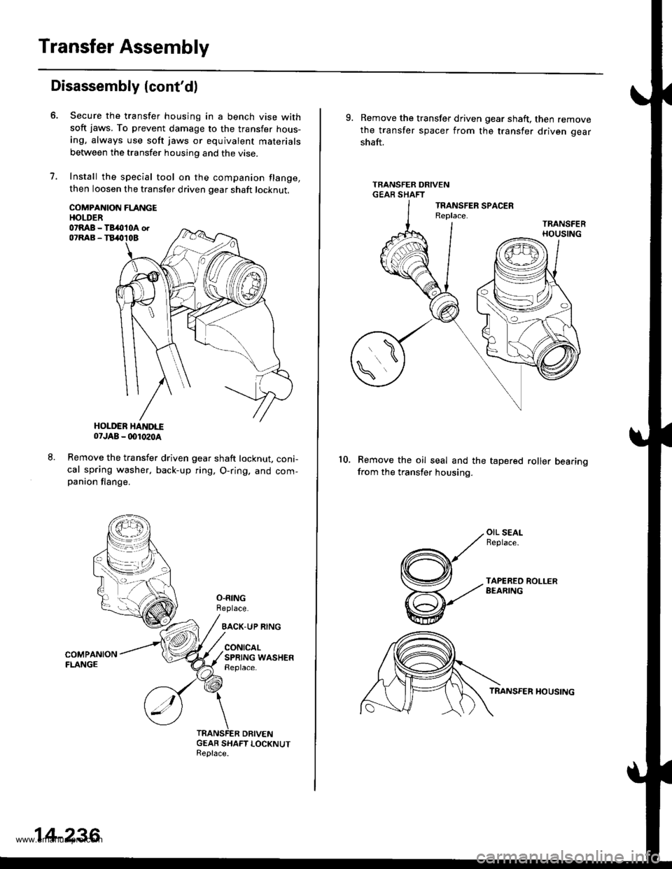
Transfer Assembly
Disassembly (cont'd)
7.
Secure the transfer housing in a bench vise withsoft iaws. To prevent damage to the transfer hous-ing, always use soft jaws or equivalent materials
between the transfer housing and the vise.
Install the special tool on the companion flange,then loosen the transfer driven gear shaft locknut.
COMPANION FLANGEHOI.DER07RAB - TB4lll0A orOTRAB - TB&TOB
HOLDER HAITDI..E07JAB _ (x)1020a
Remove the transfer driven gear shaft locknut, coni-cal spring washer, back-up ring, O-ring. and com-panion flange.
O.RINGReplace.
BACK-UP RING
CONICALSPRING WASHENReplace.
GEAR SHAFT LOCKNUTReplace.
14-236
9. Remove the transfer driven gear shaft, then removethe transfer spacer from the transfer driven gear
shaft.
TRANSFER DRIVENGEAR SHAFT
Remove the oil seal and the tapered roller bearingfrom the transfer housing.
10.
OIL SEALFeplace-
TAPEREO ROLLERBEARING
TRANSFER HOUSING
www.emanualpro.com