Page 647 of 1395

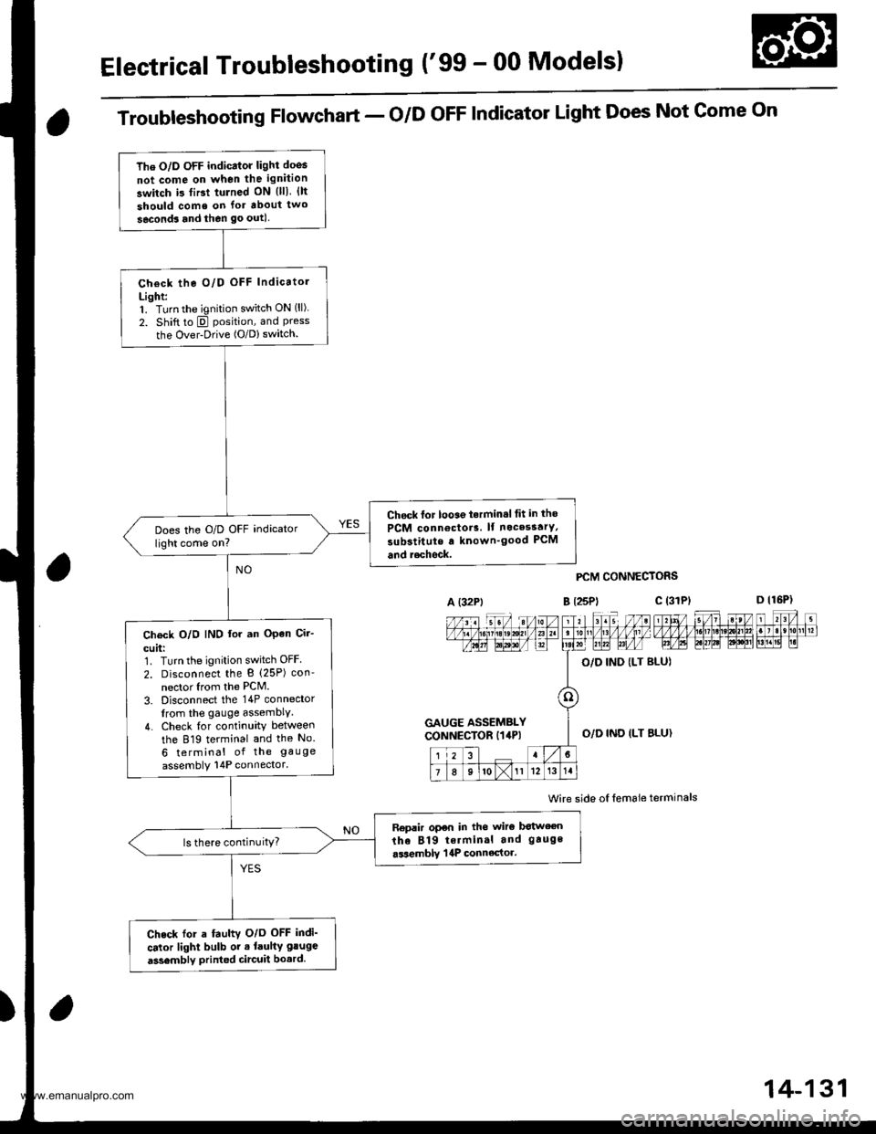
Electrical Troubleshooting ('99 - 00 Modelsl
The O/D OFF indicator light doos
not come on when the ignition
switch i3 tiBt tulned ON {lll. {lt
should come on lor about two
seconds and then go outl
Check the O/D OFF Indicatol
Light:1. Turn the ignition switch ON (ll).
2. Shift to E position, and Pressthe Over-Drive (O/D) switch.
Chock lor looae t.rmin.l tit in tho
PCM connoctor3. lf nocesstrY,
substitute a known'good PCM
and r.chock.
Does the O/D OFF indicator
light come on?
Ch€ck O/O IND lor an OPen Cir-
cuit:1. Turn the ignition switch OFF
2. Disconnect the B (25P) con'
nector Irom the PCM.
3. Disconnect the 14P connector
from the gauge assemblY.
4. Check {or continuity between
the 819 terminal and the No.
6 terminal of the gauge
assembly 14P connector.
Replir open in the wiro botween
the 819 terminal and gauge
.ssemblY | 4P connector.ls there continuitY?
Check for a fauhv O/o OFF indi'
cator light bulb or . laulty gluge
a3sembly printed circuit bo.rd.
Troubleshooting Flowchart - o/D oFF Indicator Light Does Not Gome On
A (32Pt
PCM CONNECTORS
B t25Pl c (31
Wire side oI lemale terminals
a
c (3rPt
GAUGE ASSEMBLYCONNECTOR I14P)O,/D IND ILT BLU}
14-131
www.emanualpro.com
Page 648 of 1395
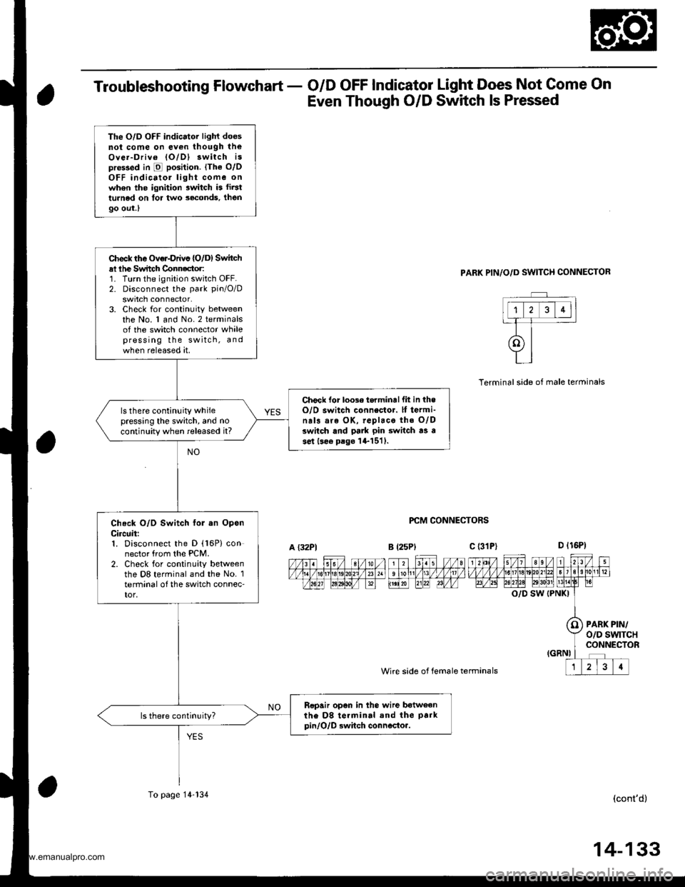
Electrical Troubleshooting ('gg - 00 Modelsl
Troubleshooting Flowchart - O/D OFF Indicator Light On Constantly
The O/D OFF indicator light is onconstanllv whenever the ignitionswitch is ON {ll),
Check the O/D OFF IndicatorLighti'1. Turn the ignition switch OFF.2. Disconnect the B (25P) con-nector from the PCM.3. Turn the ignition switch oN flt).
Does the O/D OFF indicatorlight come on?
Fepair short to ground in lhewire between the B'19 terminaland the gauge aasombly 14pGOnnectot,
14-132
www.emanualpro.com
Page 649 of 1395

Troubleshooting Flowchart - O/D OFF Indicator Light Does Not Come On
Even Though O/D Switch ls Pressed
PARK PIN/O/D SWITCH CONNECTOR
PCM CONNECTORS
Wire side of female termanals
Terminalside of male terminals
O/D SW (PNKI
PARK PIN/o/D swtTcHCONNECTOR
(cont'd)
The O/D OFF indicator light doesnot come on ev€n though theOver-Driv6 lO/Dl 3witch ispre$ed in E position. lThe o/oOFF indicatol light come onwh6n the ignition switch is fir3tturned on tor two seconds, then
9o out.l
Check the Over-Drivs {O/D) Switchal lhe Switch Connector:1. Turn the ignition switch OFF.2. Disconnect the park pin/O/D
swrtch connector.3. Check for continuity betweenthe No. 1 and No.2 terminalsof the switch connector whalepress ing the switch, andwhen released at.
Check lor loose torminallit in theO/O switch connestor. lf termi-na13 are OK, replace the O/Dswitch and pa]k pin switch as ase.t lsee p.go l+1511.
ls there continuity whilepressing the switch, and no
continuity when released it?
Check O/D Switch fol an OpsnCircuit:1. Disconnect the D (16P) connector from the PCM.2. Check for continuity betweenthe D8 terminal and the No. 1terminal o{ the switch connec'tor,
Ropair open in the wire batweanthe D8 te.minal and the park
pin/O/D Bwhch connocto..
A {32P1B l25Plc (31P)
To page 14-134
14-133
www.emanualpro.com
Page 650 of 1395
Electrical Troubleshooting ('gg - 00 Modelsl
Troubleshooting Flowchart - o/D oFF lndicator Light Does Not come on
Even Though O/D Switch ls pressed (contd)
PCM CONNECTORS
Wire side of female terminals
O/D SW {PNKI
PAFK PIN/O/D SWITCH CONNECTOR
Wire side ot female terminals
From page 14-133
Check O/D Switch Ior a Sho.tCircuit:Check for continuity between theD8 terminal and body ground.
Repair short to ground in thewire betweon the D8 terminaland the park pin/O/D.witchconnectoa,
ls there continuity?
Ch€ck O/D Switch G.ound Cir-cuit:Check lor continuity between theNo. 2 terminal of the switch con-nector and body ground.
Repair opon in the wire b€tweenth€ No. 2 terminal of the parkpinlO/D 3witch connector sndground 1G401. c402), or rep.irpoor ground (G401, 4021.
14-134
www.emanualpro.com
Page 655 of 1395
A/T Gear Position Switch
Test
1. Remove the A,/T gear position switch connsctor from the connector bracket, then disconnect the IVT gear position
switch connector (10P).
2. Check for continuity between the terminals in each switch position according to the table below.
A/T GEAR POSITIONSWITCH CONNECTOR(10P1
A/T Gear PGition Swhch Coniinuity Ch6ck'97 - 98 Models
Wire side oI female terminals
\_-__l"'ry1
Position
'l76o10
tro--o
tro------o
t!l!lo-----o
Eo_----o
Eo_-----o
Eo----o
Eo-----o
'99 - O0 Models
\______lg,-r4
Position1467.'l0
tro----o
trc\----o
Eo-----o
Eo--o
Eoo
Eo_----c
NOTE: Terminal No.3: Neutral oosition switch
14-139
www.emanualpro.com
Page 656 of 1395
A/T Gear Position Switch
Replacement
@ Make 3ure lifts, iacks, and safety stands
ar€ placod properly lsoo soction 1).
1. Raise the front of the vehicle, and support it with
safety stands (see section 1).
2. Set the parking brake, and block both rear wheels
securely.
3. Shift to E position.
Remove the A/T gear position switch connector
from the connector bracket, then disconnect it.
Remove the AfI gear position switch harness clamp.
5x1.0mm12Nm11.2kgf.m,8.7 tbf.fttBRACIGT
14-140
6. Remove the harness clamp from the end cover,
then remove the Aff gear position switch cover and
Ay'T gear position switch.
A/T GEAF POSITIONswrTcH covER6x1.0mm12 N.m 11.2 kgt m.8.7 lbf.ftl
1.Set the IVT gear position switch to E position. The
AfI gear position switch clicks in E position.
POSmON
6x1.0mm12 N.m
{1.2 kg{.m,8.7 lbtftl
swlTcH
www.emanualpro.com
Page 657 of 1395
8. Set the control shaft to E] position. then install the
A,/T gear position switch on it.
CONTROL SHAFT
Install the Ay'T gear position switch cover and har-
ness clamp on the end cover.
Connect the A,/T gear position switch connector.
then install it on the connector bracket.
Turn the ignition switch ON (ll). Move the shift lever
through all gears, and check the AfI gesr position
switch synchronization with the A/T gear position
indicator.
9.
10.
11.
A/TGEARPOSMON A/T GEAR POSITIONINDICATOR INDICATOR'99 - 00 MODELS '�97 - 98 MOOELS
12, Start the engine. Move the shift lever through all
gears. and verify the following:
. The shift lever cannot be moved to E] position
from E position unless the shift lever is pulled.
. The engine will not start in any position other
than E or E.. The back-up lights come on when the shift lever
is in El position.
14-141
www.emanualpro.com
Page 658 of 1395

A/T Gear Position Indicator
1.
f nput Test -'97 - 98 Models
Remove the gauge assembly from the dashboard (see section 20). and disconnect the 14P connector from the gauge
assemblv (see section 23),
Inspect the connector and socket terminals to be sure they are all making good contact.
. lf the terminals are bent, loose, or corroded, repairthem as necessary, and recheck the system.. lf the terminals look OK, make the following input tests at the 14P connector.- lf I test indicates a problem, find and correct the cause, then recheck the system.- lf all the input tests prove OK, but the indicator is faulty. replace the printed circuit board,
GAUGE ASSEMBLY 14P CONNECTOR
Wire side of female terminals
CavityWirs
ColorTest ConditionTest: Desir€d ResultPossible Cause
{lf rosult is not obtainod)
YEL
lgnition switch ON (ll)Check for voltage to ground:
There should be battery voltage,
. Blown No. 25 (7.5 A) fuse in the
under-dash fuse/relay box. An open in the wire
RE D/BLKCombination light
switch ON and dash
lights brightness con-
trol dial on full bright
Check for voltage between No. 2
and No. 3 terminals;
There should be battery voltage.
Blown No. 47 (7.5 A) fuse in the
under-dash fuse/relay box
Faulty combination Iight switch
Faulty dash iight brightness
controller
An open in the wire
RED
4BLUShift lever in ECheck for continuity to ground:
There should be continuity.
NOTE: There should be no continu-
ity in any other shift lever position.
' Faulty Ay'T gear position switch. An open in the wireBRNShift lever in E
7YELShift lever in @
8BLKUnder all conditionsCheck for continuity to ground:
There should be continuity
. Poor ground {G401). An open in the wire
9GRN/BLK
lgnition switch ON {ll)
and shift lever in any
position except E
Check for voltage to ground:
There should be battery voltage
for two seconds after the ignition
switch is turned ON {ll), and less
than 1 V two seconds later,
' Faulty PCM. An open in the wire
10GRNShift lever in ECheck for continuity to ground:
There should be continuity.
NOTE: There should be no conti-
nuity in any other shift lever posi-
UOn.
. Faulty A,ff gear position switch. An open in the wire1'lREDShift lever in @
12WHTShift lever in E
BLVBLU
Shift lever in ENOTE: Do not push
the brake pedal.
14LT GRN
lgnition switch ON { ll)
and shift lever in any
position except E and
E
Check for voltage to ground:
There should be about 5 V.
. Faulty PCM. An open in the wire
14-142
www.emanualpro.com