2000 HONDA CR-V Circuit
[x] Cancel search: CircuitPage 1315 of 1395
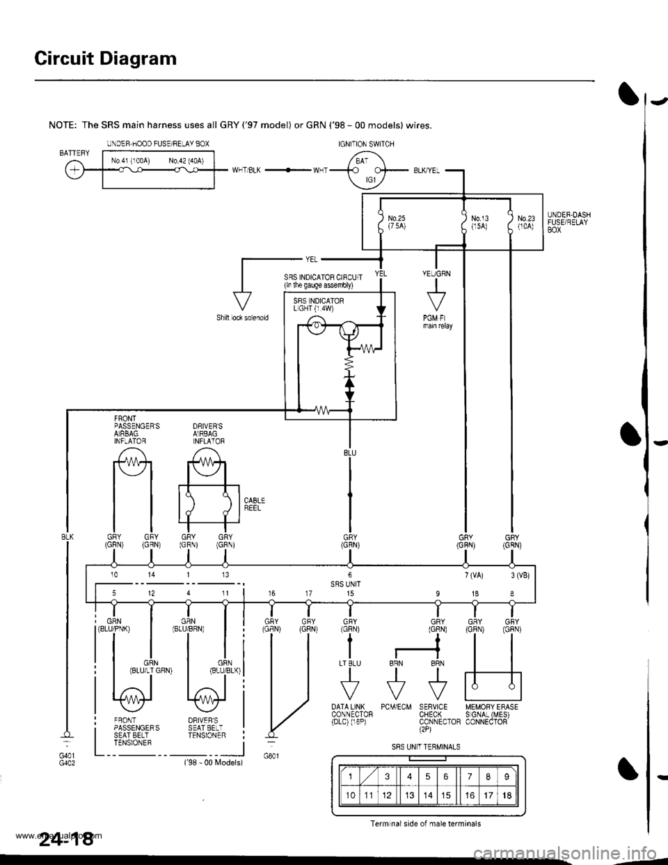
Circuit Diagram
UNDER.DASHFUSE/RELAYBOX
NOTE: The SRS main harness uses all GRY('97 model) or GRN ('98 - 00 models) wires.
WHT/BLK -'- WHT
DRIVEB'SAIRBAGNFLATOR
A
#+
tt tll./ d I
GRY GRY(GRN) (GRN)
FRONTPASSENGER'SALRBAGINFLAlOR
tlGRY GFY(GFN) (GRN)
DRIVER'SSEAT EELTTENSIONER
FRONTPASSENGERSSEAT BELTTENSIONEF
GRN(BLU/PNK)
BLK
G401
24-18
PCM/ECM SERVICE MEMORY ERASECHECK S GNAL (MES)CONNECTOB CONNECTOR(2P)
DATA LINXCONNECTOR(Drc) (r6P)
Models)('98 - 00
IGNITION SWITCHUNDEF,HOOD FUSE/RELAY BOX
YEUGRN
+
PGM FImam relay
SFS INDICATOR CIRCUIT(ln lhe gauge assembly)
Shill loc* so enoid
BLU
GR\
GNY GRY
H
GFY GRYlcFNt (GlN)
??
I r-?LT BLU BRN BRN
tttr?F?F
VVV
SRS NDICATORL GHT {r.4W)
5 12 4 11 | 16 17 15 I 18 I
10 14 113
U
S8S UN T TERMINALS
3567I
101114151718
Terminal side of male terminals
-4
www.emanualpro.com
Page 1316 of 1395
Precautions/Procedures
)General Precautions
Carefully inspect any SRS part before you install it.
Do not install any part that shows signs of being drop-
ped or improperly handled, such as dents, cracks or
deformation:
- Airbags- Cable reel- SRS unit- Seat belt tensioners
N
)-
Use only a digital multimeter to check the system, lf
it's not a Honda multimeter, make sure its output is
10 mA (0,01 A) or less when switched to the smallest
value in the ohmmeter range. A tester with a higher
output could damage the airbag circuit or cause acci-
dental deployment and possible injury.
Do not install used SRS Dans from another vehicle,
When making SRS repairs, use only new pans.
Except when performing electrical inspections,
always disconnect both the negative cable and posi-
tive cable from the batterv. and wait at least three
minutes before beginning work.
Replacement of the combination light and wiper/
washer switches and cruise control switch can be
done without removing the steering wheel:
- Combination light and wiper/washer switch replace-
ment {see section 231.- Cruise control sevresume switch replacement (see
section 41.
Whenever the ignition switch is ON {ll}, or has been
turned OFF for less than three minutes, be careful not
to bump the SRS unit; the airbags could accidentally
deploy and cause damage or injuries.
Whenever the airbag has been activated, replace the
SRS unit.
The original radio has a coded theft protection circuit.
Be sure to get the customer's code number before dis-
connecting the battery cables.
)
Airbag/Seat Belt Tensioner
Handling and Storage
Do not try to disassemble an airbag or a seat belt ten-
sioner. They have no serviceable parts. Once an airbag
or a seat belt tensioner have been deployed. they cannot
be repaired or reused.
For temporary storage of an airbag or a seat belt ten-
sioner during service, please observe the following pre-
cautons:
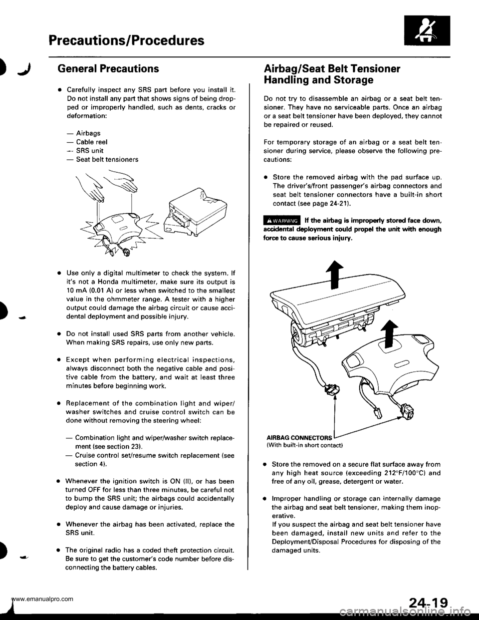
. Store the removed airbag with the pad surface up.
The driver's/front passenger's airbag connectors and
seat belt tensioner connectors have a built-in short
contact (see page 24-211.
@ r th€ airb.g is impropcrty stor€d face down,
accidental deployment could propel the unit with enough
forc€ to caus6 serious iniury,
Store the removed on a secure flat surface awav from
any high heat source (exceeding 212"F/100'C) and
free of any oil, grease. detergent or water.
lmproper handling or storage can internally damage
the airbag and seat belt tensioner. making them inop-
erative.
lf you suspect the airbag and seat belt tensioner have
been damaged, install new units and refer to the
Deploymenvoisposal Procedures for disposing of the
damaoed units.
AIRBAG CONNECTORS
www.emanualpro.com
Page 1323 of 1395
Troubleshooting
Self-diagnostic Procedures
The self-diagnostic function of the SRS system allows it to locate the causes of system problems and to store this informa-
tion in memory, For easier troubleshooting, this data can be retrieved via a data link circuit.
. When you turn the ignition switch ON (ll). the SRS indicator will come on. lf it goes off after six seconds, the system is
normal.
. lf there is 8n abnormality, the system locates and defines the problem. stores this information in memory, and turns
the SRS indicator light on. The data will remain in the memory even when the ignition switch is turned off or if the bat-
terv is disconnected.
. When you connect the SCS service connector to the service check connector (2P), and turn the ignition switch ON (ll),
the SRS indicator light will indicate the diagnostic trouble code (DTC) by the number of blinks.
. After reading and recording the DTC, proceed with the troubleshooting forthis code.
Precsutions
. Use only a digital multimeter to check the system. lf it's not a Honda multimeter. make sure its output is 10 mA (0.01 A)
or less when switched to the smallest value in the ohmmeter range. A tester with a higher output could damage the
airbag circuit or cause accidental airbag deployment and possible injury.
. Whenever the ignition switch isON (ll). or has been turned OFF for less than three minutes, be careful nottobumpthe
SRS unit; the airbags could accidentally deploy and cause damage or injuries.
. Before you remove the SRS main harness, disconnect the airbag and tensioner connectors (see page 24-23).
. Make sure the battery is sufficiently charged (see section 23). lf the battery is dead or low, measuring values won't be
correct.
. Do not touch a tester probe to the terminals in the SRS unit or harness connectors, and do not connect the terminals
with a jumper wire. Use only the backprobe set and the SCS service connector.
For backprobing spring-loaded lock type con nectors, .efet to page 24-22.
Reading the DTC
When the SRS indicator light is on, read the DTC using one of these methods;
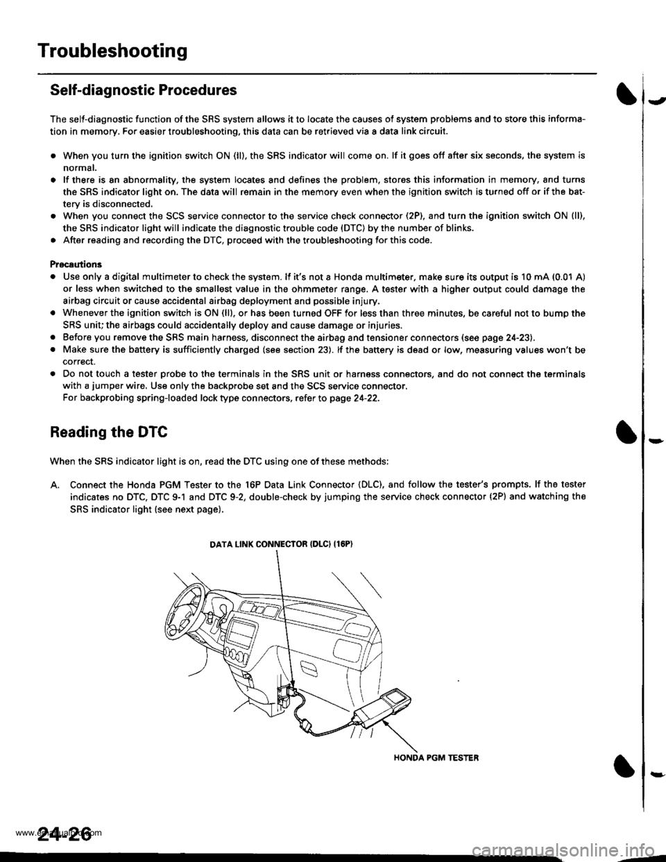
A. Connect the Honda PGM Tester to the 16P Data Link Connector {DLC), and follow the tester's prompts. lf the tester
indicates no DTC, DTC 9-1 and DTC 9-2, double-check by jumping the service check connector (2P) and watching the
SRS indicator light (see next page).
HONDA PGM TESTER
DATA LINK CONNECIOR {DLCI {16P)
24-26
,1
www.emanualpro.com
Page 1326 of 1395
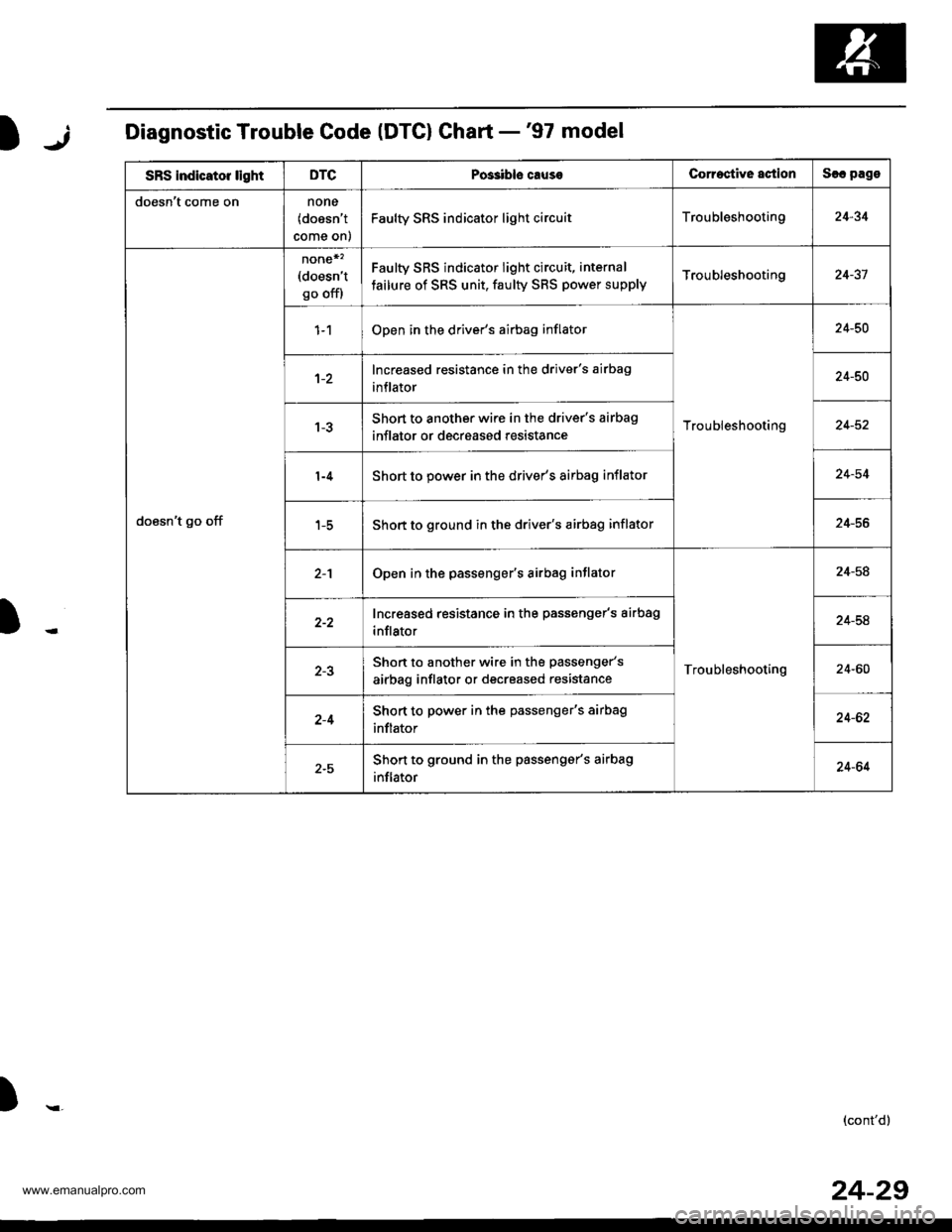
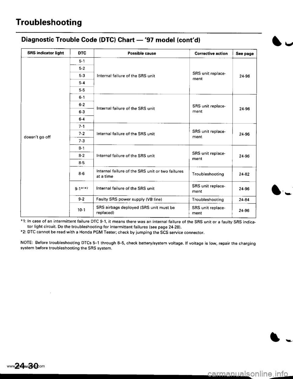
jIDiagnostic Trouble Code (DTG) Ghart -'97 model
SRS indicator lightDTCPos3ibls causeCorroctive actionSlc pago
doesn't come onnone(doesn't
come on)
Faulty SRS indicator light circuitTroubleshooting24-34
doesn't go off
none*'�(doesn't
go off)
Faulty SRS indicator light circuit, internal
tailure of SRS unit, faulty SBS power supplyTroubleshooting24-37
Open in the driver's airbag inflator
Troubleshooting
24-50
Increased resistance in the driver's airbag
inflator24-50
Short to another wire in the driver's airbag
inflator or decreased resistance24-52
Short to power in the driver's airbag inflator24-54
Short to ground in the driver's airbag inflator24-56
Open in the passenger's airbag inflator
Troubleshooting
24-58
Increased resistance in the passenger's airbag
inflator24-54
Shon to another wire in the passenger's
airbag inflator or decreased resistance24-60
2-4Short to power in the passenger's airbag
inflator24-62
2-5Shon to ground in the passengar's airbag
inflator24-64
)r,(cont'd)
24-29
www.emanualpro.com
Page 1327 of 1395
Troubleshooting
Diagnostic Trouble Code (DTC) Chart -'97 model (cont'dl
*1: In case of an intermittent failure DTC 9-1, it means there was an internal failure of the SRS unit or a faultv SRS indica-tor light circuit. Do the troubleshooting for intermittent failures {see page 24-28),*2: DTC cannot be read with a Honda PGM Tester; check by jumping the SCS service connector.
NOTE: Before troubleshooting DTCS 5-1 through 8-5, check battery/system voltage. lf voltage is low. repair the chargingsystem before troubleshooting the SRS system.
l*
SRS indicator lightDTCPossible causeCorrestive actionSee page
doesn't go off
Internal failure of the SRS unitSRS unit replace-
ment24-965-3
5-4
5-5
o-l
Internal failure of the SRS unitSRS unit replace-
ment24-966-2
6-4
lnternal failure of the SRS unitSRS unit replace-
ment24-967-2
7-3
8-1
Internal failure of the SBS unitSRS unit replace-
menr24-96a-2
8-5
8-6Internal failure of the SRS unit or two failures
at a timeTroubleshooting24-82
Internal failure of the SRS unitSRS unit replace-
menr24-96
9-2Faulty SRS power supply (VB line)Troubleshooting24-84
'10- 1SRS airbags deployed (SRS unit must be
replaced)
SRS unit replace-
ment24-96
24-30
--
www.emanualpro.com
Page 1328 of 1395
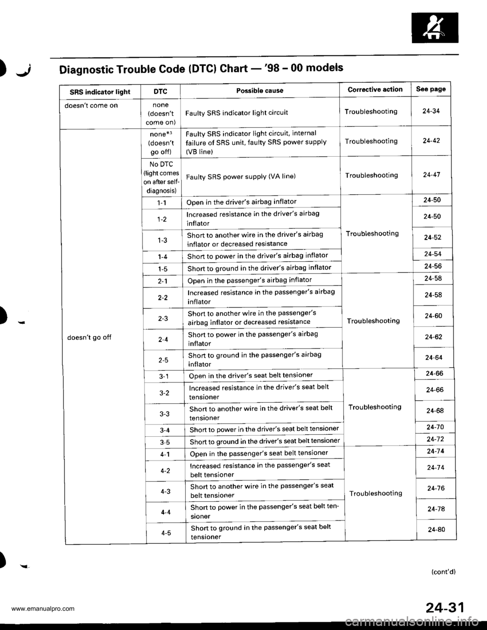
);Diagnostic Trouble Code (DTCI Chart -'98 - 00 models
SRS indicator lightDTCPossibls causeCorrectiva agtionSee page
doesn t come onnone
(doesn't
come on)
Faulty SRS indicator light circuitTroubleshooting24-34
doesn't go off
none*3
{doesn'tgo off)
No DTC
(light comes
on after self-
diagnosis)
Faulty SRS indicator light circuit. internal
failure of SRS unit, faulty SRS power supply
(VB line)
Troubleshooting24-42
Faulty SRS power supply (VA line)Troubleshooting24-47
1-1Open in the driver's airbag inflator
Troubleshooting
24-50
lncreased resistance in the driver's airbag
inflator24-50
1-3Short to another wire in the driver's airbag
inflator or decreased reslstance24-52
1-4Short to power in the driver's airbag inflator24-54
1-5Short to ground in the driver's airbag inflator24-56
2-1Open in the passenger's airbag inflator
Troubleshooting
24-54
Increased resistance in the passenger's airbag
inflator24-58
Shon to another wire in the passenger's
airbag inflator or decreased resistance24-60
2,4Short to power in the passenger's airbag
inflator24-62
Short to ground in the passenger's arrbag
inflator24-64
3-1Open in the driver's seat belt tensioner
Troubleshooting
24-66
3-2lncreased resistance in the driver's seat belt
tensroner24-66
Shon to another wire in the driver's seat belt
tensroner24-64
3-4Short to power in the driver's seat belt tensioner24-10
Short to ground in the driver's seat belt tensloner24-7 2
4-1Open in the passenger's seat belt tensioner
Troubleshooting
24-14
Increased resistance in the passenger's seat
belt tensioner24-7 4
4-3Short to another wire in the passenger's seat
belt tensioner24-7 6
4-4
4-5
Short to power in the passenger's seat belt ten-
sroner24-74
Shon to ground in the passenger's seat belt
tensroner24-AO
)-(cont'd)
24-31
www.emanualpro.com
Page 1329 of 1395
Troubleshooting
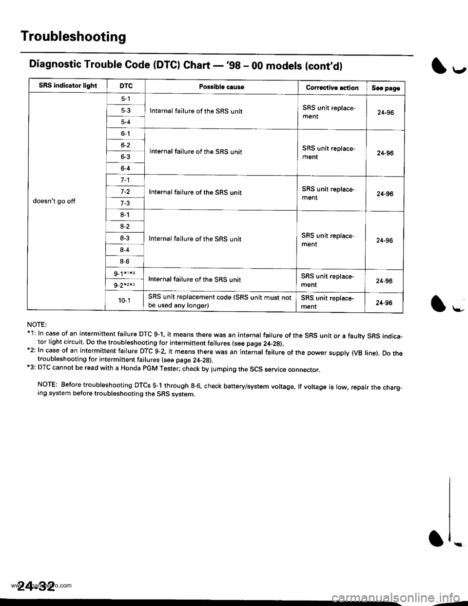
SRS indicator lightDTCPo$ibla causeCorroctive lctionSec pag€
doesn't go off
5-l
Internal failure of the SRS unitSRS unit replace-
ment24-96
5-4
6-1
lnternal failure of the SRS unitSRS unit replace-
ment24-966-3
6-4
Internal failure of the SRS unitSRS unit replace-
ment24-96
8-1
Internal failure of the SRS unitSRS unit replace-
ment24-96
8-2
8-3
8-4
8-6
Internal failure of the SRS unitSRS unit.eplace-
ment24-969_2*2*3
10- 1SRS unit replacement code (SRS unit must notbe used any longer)SRS unit replace-
ment24-96
Diagnostic Trouble Code (DTC) Chart -'98 - 00 modets (cont,dl
NOTE:*1: In case of an intermittent failure DTC g-1, it means there was an internal failure of the SRS unit or a faulw SRS indica-tor light circuit. Do the troubleshooting for intermittent failures (see page 2,+_2g),*2: In case of an intermiuent fairure DTc 9-2, it means there was an internar fairure of the power suppry (vB rine). Do thetroubleshooting for intermittent failures (see page 24-29).*3: DTC cannot be read with a Honda PGM Tester; check by jumping the SCS servic€ connector.
NOTE: Before troubleshooting DTCS 5-1 through g-6. check battery/system voltage. lf voltage is low, repair the charg_ing system before troubleshooting the SRS system.
l*-
1,.-
\f ..
24-32
--
www.emanualpro.com
Page 1330 of 1395
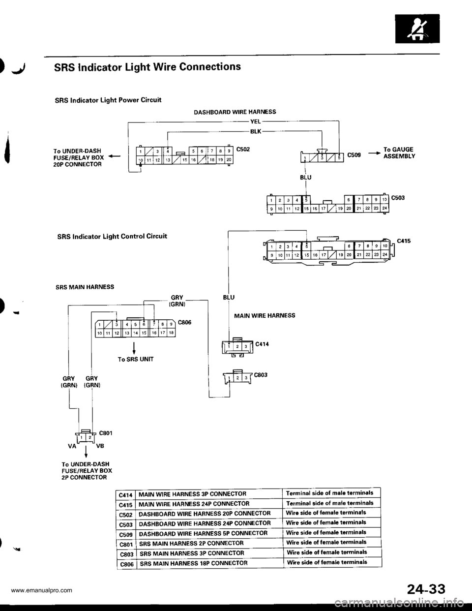
SRS Indicator Light Wire Connections
SRS Indicator Light Power Circuit
DASHBOARD WIRE HARNESS
YEL
BLK
To UNDER-DASHFUSE/RELAY BOX <_
20P CONNECTOR
To GAUGEcsog + assEMBLy
SRS Indicator Light Control Circuit
SRS MAIN HARNESS
)-MAIN WIRE HARNESS
VAIVBIt
To UNDER-DASHFUSE/BELAY BOX2P CONNECTOR
c414MAIN WIRE HARNESS 3P CONNECTORTerminal side of msle t€rminals
c415MAIN wlRE HARNESS 24P CONNECTORTerminal aide of male terminals
c502DASHBOARD WIRE HARNESS 2OP CONNECTORWire side of lemslo terminsls
c503OASHBOARD WIRE HARNESS 24P CONNECTORWire side of female t€rminal3
c509DASHBOABD WIRE HARNESS 5P CONNECTORWire sid€ ot lemale te.minals
c801SRS MAIN HARNESS 2P CONNECTORwire side ol f.male terminals
c803SRS MAIN HARNESS 3P CONNECTORWire side ol female terminals
c806SRS MAIN HARNESS T8P CONNECTORWire side of lomrle terminals
)
24-33
www.emanualpro.com