2000 HONDA CR-V charging
[x] Cancel search: chargingPage 82 of 1395
Charging System
IRectifier Test
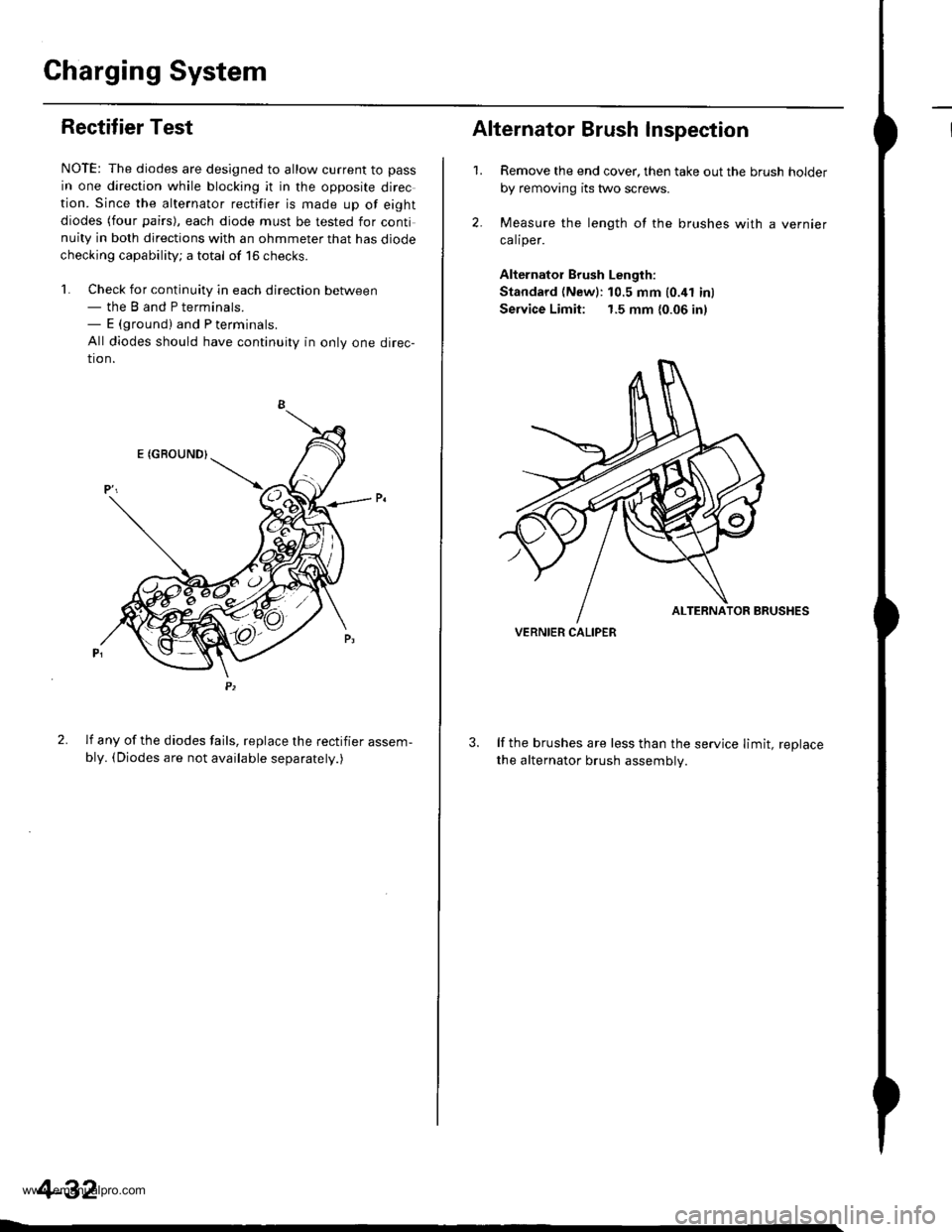
NOTE: The diodes are designed to allow current to pass
in one direction while blocking it in the opposite direc
tion. Since the alternator rectifier is made up of eight
diodes (four pairs), each diode must be tested for continuity in both directions with an ohmmeter that has diode
checking capability; a total of 16 checks.
'l. Check for continuity in each direction between- the B and P terminals.- E (ground) and P terminals.
All diodes should have continuity in only one direc-
tion.
2. lf any of the diodes fails, replace the rectifier assem-
bly. (Diodes are not available separatelv.)
4-32
1.
Alternator Brush Inspection
2.
Remove the end cover, then take out the brush holder
by removing its two screws.
Measure the length of the brushes with a vernier
calrper.
Alternator Brush Length:
Standard (Newl:10.5 mm 10.41 inl
Service Limit: 1.5 mm {0.06 in)
lf the brushes are less than the service limit, replace
the alternator brush assemblv.
VERNIER CALIPER
www.emanualpro.com
Page 84 of 1395
Charging System
Alternator Belt Inspection and Adjustment
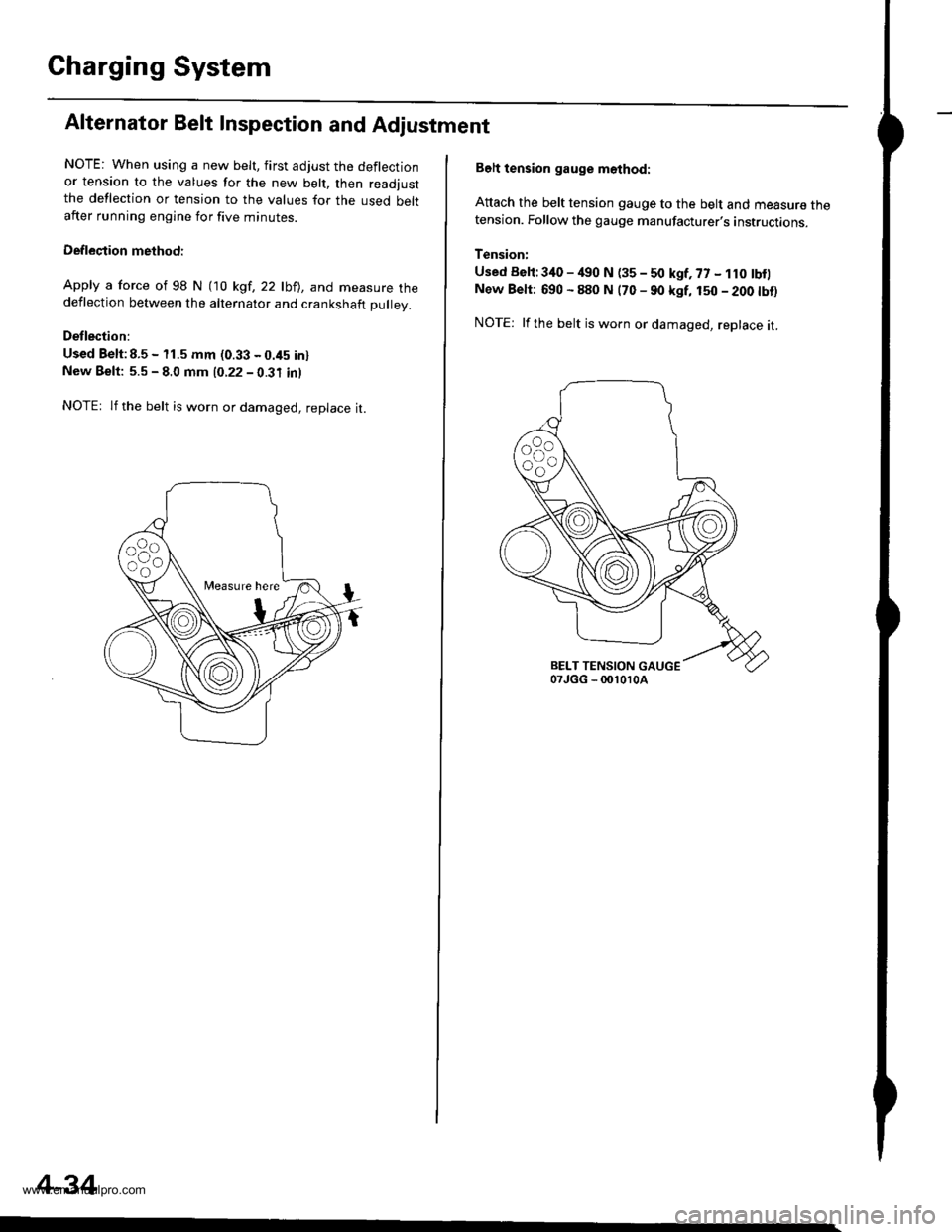
NOTE: When using a new belt, first adjust the deflectionor tension to the values for the new belt, then readjustthe deflection or tension to the values for the used beltafter running engine for five minutes.
Deflection methodi
Apply a force of 98 N (10 kgt,22lbll, and measure thedeflection between the alternator and crankshaft pulley.
Detlection:
Used Belt:8.5 - 11.5 mm (0.33 - 0.45 inlNew Beft: 5.5 - 8.0 mm 10.22 - 0.31 inl
NOTEr lf the belt is worn or damaged, replace it.
Measure here
4-34
Belt tension gauge m6thod:
Attach the belt tension gauge to the belt and measure thetension. Follow the gauge manufacturer's instructions.
Tension:
Used Belt:340 - /€0 N (35 - 50 kgf, 77 - 1r0 tbf)New Belt: 690 - 880 N (70 - 90 kgf, 150 - 200 tbt)
NOTE: lfthe belt is worn or damaged, replace it.
www.emanualpro.com
Page 282 of 1395

PGM-FI System
System Description
INPUTS
CKP/TDC/CYP Sensor
CKF Sensor
MAP Sensor
ECT Sensor
IAT Sensor
TP Sensor
Primary HO2S
Secondary H02S
vss
KS*5
BARO Sensor
ELD*6
Starter Signal
ALT FR Signal
Air Conditioning Signal
Ay'T Gear Position Signal*1
Baftery Voltage (lGN.1)
Brake Switch Signal
PSP Switch Signal
Fuel Tank Pressuae Sensor*4. *5
Countershaft Speed Sensor*1
Mainshaft Speed Sensor*r
OVER-DRIVE Switch Signal*s
ENGINE CONTROL MODULE (ECM)/
POWERTRAIN CONTROL MODULE (PCM) OUTPUTS
|iuel 1"j""- Th,rhg ""d Drrafr";-l
Et*-.nt"tdt"cont.orl
to,r*,c;;trffi;]
l.----.---:. .Lrgnrnon |lmrng Lonrror I
Ecir/PcM B*k',p Fr""il]
m;"t-ll-r*'io*l
Fuel Injectors
PGM-Fl Main Relay (Fuel Pump)
MIL
IAC Valve
Ay'C Compressor Clutch Relay
Radiator Fan Relay
Condenser Fan Relay
ALT
tcM
EVAP Purge Control Solenoid
Valve
Primary HO2S Heater
Secondary H02S HeaterEVAP Bypass Solenoid Valve*a *5
EVAP Control Canister Vent Shut
DLC
Lock-up Control Solenoid Valve*l
Shift Control Solenoid Valve*1
Ay'T Clutch Pressure Control
Solenoid Valve*1
D4 Indicator Light'1 *3, *a
D Indicator Light,l *5
OVER-DRIVE OFF Indicator
Lighl*t *:
*1: A/T {3:'97 model'2: M/f +4:'98 model*5: '99 - 00 models"6: USA
PGM-Fl System
The PGM-Fl system on this model is a sequential multiport fuel injection system.
Fuel iniecior Timing and Duration
The ECM/PCM contains memories for the basic discharge durations at various engine speeds and manifold pressure. The
basic discharge duration, after being read out from the memory, is further modified by signals sent from various sensors
to obtain the final discharge duration.
ldle Air Control
ldle Air Control Valve (lAC Valve)
When the engine is cold, the Ay'C compressor is on, the transmission is in gear, the brake pedal is depressed, the P/S load
is high, or the alternator is charging, the ECM/PCM controls current to the IAC Valve to maintain the correct idle speed.
lgnition Timing Control
o The ECM/PCM contains memories for basic ionition timing at various engine speeds and manifold air flow rates.
lgnition timing is also adjusted for engine coolant temperature.
. A knock control system was adopted which sets the ideal ig nition timing for the octane rating of the gasoline used.*s
Other Control Funstions
1. Starting Control
When the engine is started. the ECM/PCM provides a rich mixture by increasing fuel injector duration.
2. Fuel Pump Control
. When the ignition switch is initially turned on (ll). the ECMiPCM suppli€s ground to the PGM-FI main relay that
supplies current to the fuel pump for two seconds to pressurize the fuel system.
. When the engine is running, the ECM/PCM supplies ground to the PGM-FI main relay that supplies current to the
fuel oumo.
. When the engine is not running and the ignition is on, the ECM/PCM cuts ground to the PGM-FI main relay which
cuts current to the fuel pump.
1 1-80
www.emanualpro.com
Page 284 of 1395
PGM-FI System
Powertrain Control Module {PCM} -'97 Model
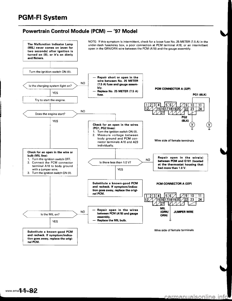
NOTE: lf this symptom is intermiftent, check for a loose fuse No. 25 METER (7.5 A) in theunderdash f{rse/relay box, a poor connection at PCM terminal A18, or an intermittentopen in the GRN/ORN wire between the PCM (A18) and the gauge assembly.
PCM OON ECTOR A {32P}
Wire side of female terminals
PCM CONNECTOR A {32PI
Wire side ot temale terminals
11-42
The Malfunction lndicator LamD(MlL) nev6r comes on {even lortwo seconds) after ignition isturned on (lll, or it's on dimlyand flickers.
Turn the ignition switch ON {ll}.
- Rep.ir short or opon in thowire batween No. 25 METER(7.5 Alfuso and gauge a$€m-bty.- R6pl.c€ No. 25 METER 17.5 Alfus€.
ls the charging system light on?
Try to stan the engine.
Does the engine start?
Chock tor.n open in th6 wire3{PG1, PG2linesl:1. Turn the ignition switch ON (ll).2. Measure voltage betweenbody ground and PCM con-nector terminals A10 and A23individually.
Check for an op€n in the wir6 orbulb (MlL lin€l:1. Turn the ignition switch OFF.2. Connect the PCM connectorterminal A18 to body groundwith a iumper wire.3. Turn the ignition switch ON {ll).
n€peir open in tho wirelslhwoon PCM and Glol (loc!t.d
at thc tha.mo3tat houling thrthtd moro th.n 1.0 V.
ls thore l€ss than 1.0 V?
Substituto . known-good PCMand r€check. ll symptom/indica-tion goss away, rcplaca the origi-nal PCM.
- R6pai. open in th. wileibelwoon rcM lAl8l dnd g.ugea3rombly.- Roolac€ the MIL bulb.
ls the MIL on?
Substitut6 a known-good PCMand rocheck. ll 3ymptom/indica-tion goes away, replace the o.igi-n.l PCM.
PGl IBLKI
www.emanualpro.com
Page 361 of 1395
Alternator (ALT) FR Signal
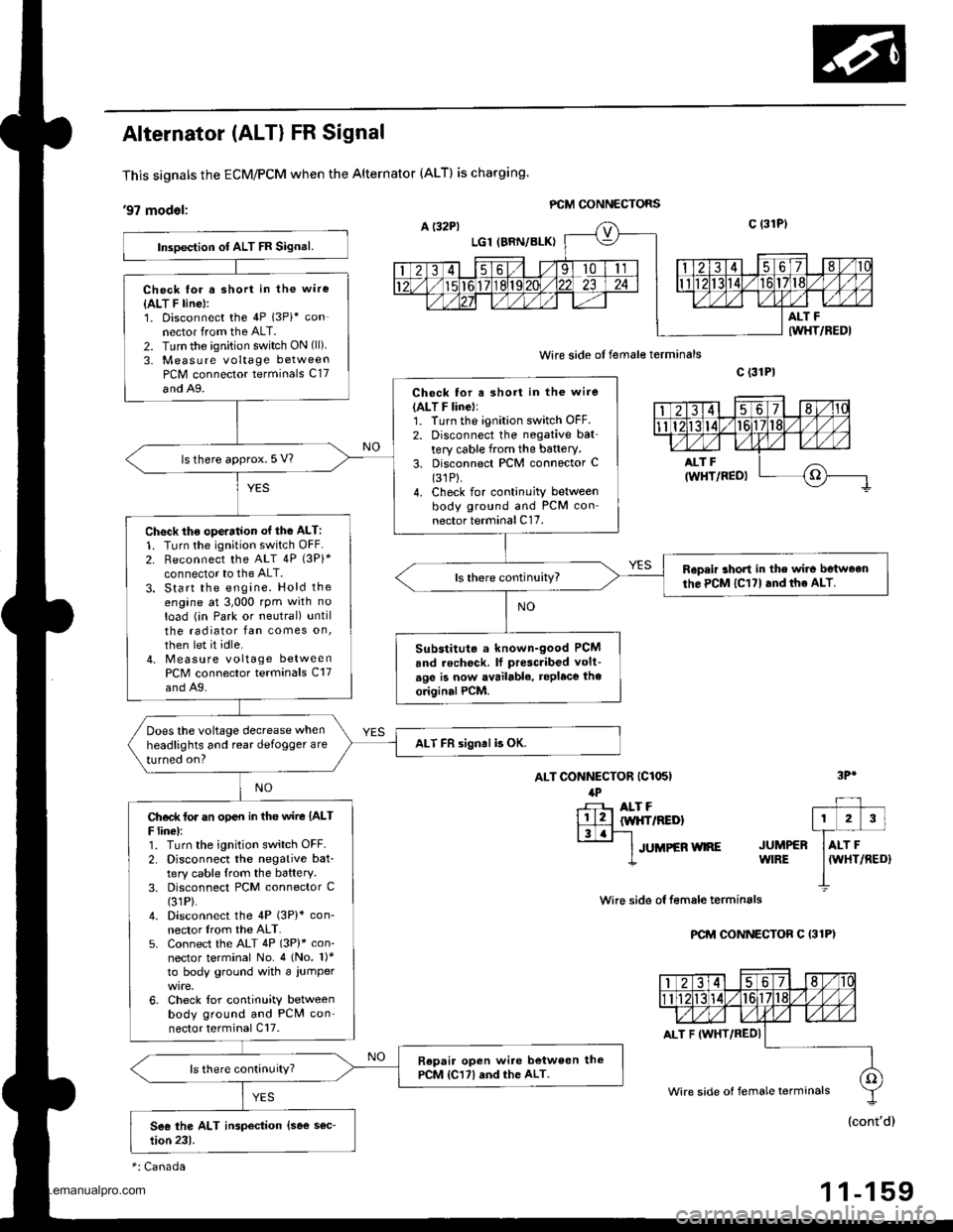
This signals the ECM/PCM when the Alternator (ALTI is charging.
,97 modet: PCM GONNECTORS
wire side of female terminals
ALT CONNECTOR (C1O5I
lPr-F- ALT F
lll2llw|{frREDl|3.r-'l-
lruueen wne
c (31P|
wire side ol f€male terminals
PCM CONNECTOR C I31P)
3Pr
JUMPERWIRE
Inspection ot ALT FR Signal.
Check lor a short in the wire
{ALT F line}:1. Disconnect the 4P 13Pi* connector from the ALT.2. Turn the ignition switch ON (ll)
3, Measure voltage betweenPCM connector terminals C17
and A9.Check for a short in the wire(ALT F linel:1. Turn the ignition switch OFF.2. Disconnect the negative bat'tery cable from the battery.3. Disconnect PCM connector C(31P).
4. Check for continuity betweenbody ground and PCM connector terminal C17.
ls there approx. 5 V?
Check th€ ope.ation of the ALT:
1. Turn the ignition switch OFF2. Reconnect the ALT 4P {3Pi*connector to the ALT.3. Start the engine. Hold theengine at 3,000 rpm with no
load (in Park or neutral) untilthe radiator fan comes on,
then let it idle.4. Measure voltage betweenPCM connector terminals C17and A9.
Ropeir short in the wir6 betweonthe PCM lC17l and the ALT.
Substitut. a known-good PCM
and recheck. lf prescribed volt-
age is now availablo, replace the
originalPCM.
Does the voltage decrease when
headlights and rear defogger are
turned on?ALT FR signal b OK.
Ch€d( for an op€n in tho wire IALTF linel:1. Turn the ignition switch OFF.2. Disconnect the negative bat-tery cable lrom the battery.3. Disconnect PCM connector C(31P).
4. Disconnect the 4P (3P)* con-nector lrom the ALT.5. Connect the ALT 4P (3P)* con-nector terminal No. 4 (No. 1)*to body ground with a iumper
6. Check for continuity betweenbody ground and PCN4 con'nector terminal Cl7.
Repair open wi.e between thePCM lCl7l and the ALT.ls there continuity?
ALT F IWHT/REDI
Wire side of female terminals
1 1-159
www.emanualpro.com
Page 1091 of 1395
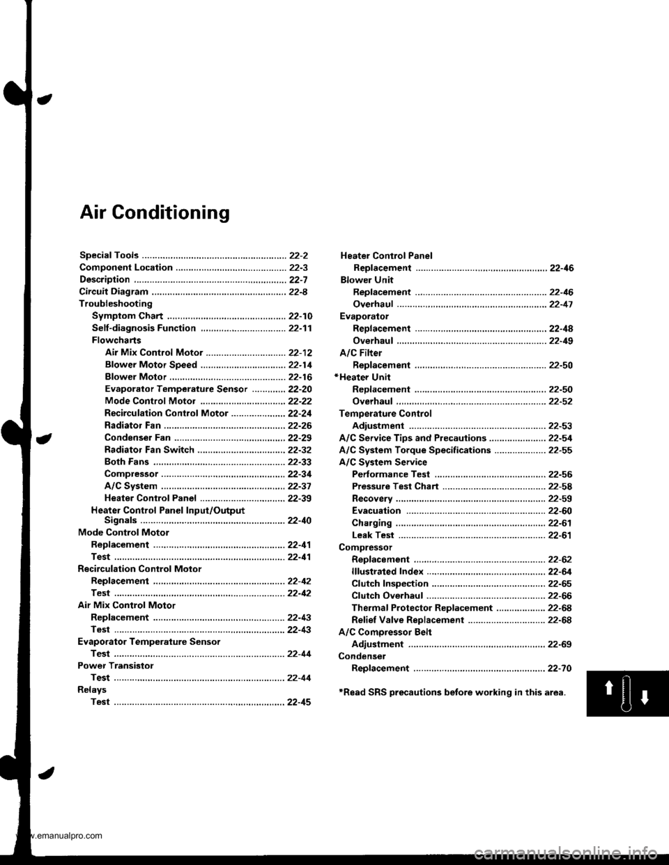
Air Conditioning
Heater Control Panel
Reofacement ,.,...,,.,..,.,.,,22-46
Blower Unit
Replacement .................. 22-46
Overhaul ...........,,,., .......-.22-17
Evaporalor
ReDlacement ...,.,.,..,......,22-4A
Overhaul ................ .........22-19
A/C Filter
Replacement ..................22-50*Heater Unit
ReDfacement ..................22-50
Overhaul ..,.,..,.,...,.. .........22-52
Temperature Control
Adiustment ....................22-53
A/C Service Tips and Precauiions............-....-.... 22-54
A/C System Torque Specifications .................... 22-55
A/C System Service
Performance Test ......,...22-56
Pressure Test Chart .-.....22-5a
Recovery ..............,. ...-.-...22-59
Evacuation -...........-........22-60
Charging ................ .......-.22-61
Leak Test ........................22-61
Compressor
Repfacement ..........-.......22-62
flfustrated Index .....,.......22-64
Cfutch fnspection .........,.22-65
Cfutch Overhaul ............- 22-66
Thermaf Protector Rep|acement ................... 22-68
Refief Valve Replacement .............................. 22-68
A/C Comoressor Belt
Adiustment .................... 22-69
Condenser
Repfacement .,.....,,.,..,.,..22-70
'Read SRS precautions betore working in this area.
www.emanualpro.com
Page 1097 of 1395
Description
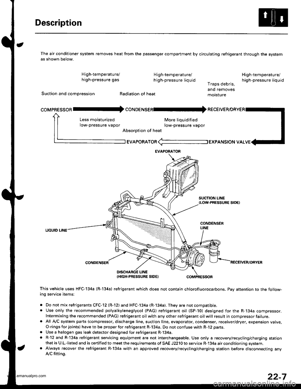
The air conditioner system removes heat from the passenger compartment by circulating refrigerant through the systemas shown below.
High'temperature/ High-temperature/
high-pressure gas h igh-pressure liquid
Suction and compression Radiation of heat
High-temperature/
high-pressu re liq uidr raps oeons,
and removes
motsture
More liquidified
row-pressure vapor
EVAPoRAToR (-l EXPANSToN vAL
SUCTION LINEtLow-PRESSURE S|OEt
LIOUID LINE
CONDENSER
coMpREssoR Il- coruoerusenl* necetve
Less moisturized
low-pressure vapor
Absorption of heat
DISCHARGE LINEIHIGH.PRESSURE SIDEI
This vehicle uses HFC-I34a (R-l34a) refrigerant which does not contain chlorofluorocarbons. Pay attention to the follow-ing service items:
. Do not mix refrigerants CFC-12 (R-12) and HFC-l34a (R-134a). They are not compatible.. Use only the recommended polyalkyleneglycol (PAG) refrigerant oil (SP-10) designed for the R-134a compressor.Intermixing the recommended (PAG) refrigerant oil with any other refrigerant oil will result in compressor failure.. Afl Ay'C system parts (compressor, discharge line. suction line, evaporator, condenser. receiver/dryer, expansion valve,O-rings for joints) have to be proper for refrigerant R-134a. Do not confuse with R-12 parts.
. Use a halogen gas leak detector designed for refrigerant R-134a.. R-12 and R-134a refrigerant servicing equipment are not interchangeable. Use only a recovery/recycling/charging stationthat is U.L.iisted and is certified to meet the requirements of SAE J2210 to service R-134a air conditioning system.. Always recover the refrigerant R-134a with an approved recovery/recycling/charging station before disconnecting anylVC fitting.
EVAPORAYOR
22-7
www.emanualpro.com
Page 1138 of 1395
Evaporator
Replacement
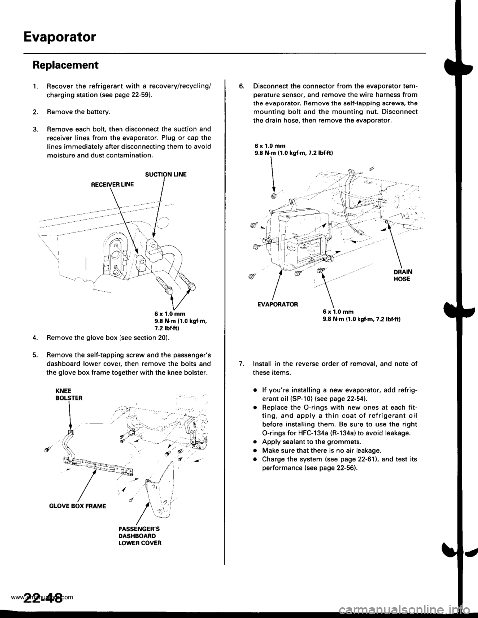
1.Recover the refrigerant with a recovery/recycling/
charging station (see page 22-59).
Remove the battery.
Remove each bolt, then disconnect the suction and
receiver lines from the evaporator. Plug or cap the
lines immediately after disconnecting them to avoid
moisture and dust contamination,
RECEIVER LINE
..
\
6x1.0mm9.8 N'm (1.0 kgf m,7.2 tbl.ttl
Remove the glove box (see section 20).
Remove the self-tapping screw and the passenger's
dashboard lower cover, then remove the bolts and
the glove box frame together with the knee bolster.
GLOVE BOX FRAME
KNEE
22-44
6. Disconnect the connector from the evaoorator tem-
oerature sensor. and remove the wire harness from
the evaporator. Remove the self-tapping screws, the
mounting bolt and the mounting nut. Disconnect
the drain hose, then remove the evaporator.
5xl,0mm9.8 N.m {1.0
II
I
Io
kgf.m, 7.2 lbf.ftl
, -l: "
7.
EVAPORATOR
6x1.0mm9.8 N.m (1.0 kgtm,7.2lbf.ftl
Install in the reverse order of removal, and note of
these items.
. lf you're installing a new evaporator, add refrig-
erant oil (SP.10) (see page 22-541.
Replace the O-rings with new ones at each fit-
ting, and apply a thin coat of refrigerant oil
before installing them. Be su.e to use the right
O-rings for HFC-134a (R-134alto avoid leakage.
Apply sealant to the grommets.
Make sure that there is no air Ieakage.
Charge the system (see page 22-6'll, and test its
performance (see page 22-56]-,
a
a
a
www.emanualpro.com