Page 1093 of 1395
Component Location
lndex
EVAPORATORReplacement, page 22-48Overhaul, page 22-49
SERVICE VALVEILOW-PRESSURE SIDE}
CONDENSERReplacement, page 22-70
A/C PRESSURE SWTTCHWhen the refrigorant pressure is below 200 kPa 12.0 kglc.r|r,28 psi) or abov€ 3,200 kPa (32 kgflcmr, 455 psi), the AJC pressureswitch opens the circuit to the Ay'C switch and stops the airconditioning to protect the compressor.
Replacement, page 22-62Clutch Inspection, page 22-65Clutch Overhaul, pago 22-66Thermal Protector Replacement, page 22-68Relief Valve Replacem€nt. page 22-68
SERVICE VALVEIHIGH-PRESSURE SIDEI
,
[\,
-il
(cont'd)
www.emanualpro.com
Page 1097 of 1395

Description
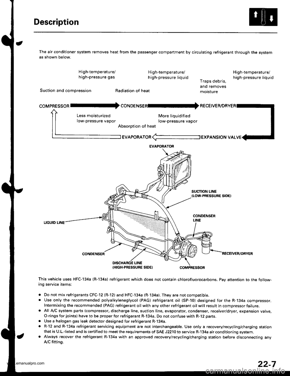
The air conditioner system removes heat from the passenger compartment by circulating refrigerant through the systemas shown below.
High'temperature/ High-temperature/
high-pressure gas h igh-pressure liquid
Suction and compression Radiation of heat
High-temperature/
high-pressu re liq uidr raps oeons,
and removes
motsture
More liquidified
row-pressure vapor
EVAPoRAToR (-l EXPANSToN vAL
SUCTION LINEtLow-PRESSURE S|OEt
LIOUID LINE
CONDENSER
coMpREssoR Il- coruoerusenl* necetve
Less moisturized
low-pressure vapor
Absorption of heat
DISCHARGE LINEIHIGH.PRESSURE SIDEI
This vehicle uses HFC-I34a (R-l34a) refrigerant which does not contain chlorofluorocarbons. Pay attention to the follow-ing service items:
. Do not mix refrigerants CFC-12 (R-12) and HFC-l34a (R-134a). They are not compatible.. Use only the recommended polyalkyleneglycol (PAG) refrigerant oil (SP-10) designed for the R-134a compressor.Intermixing the recommended (PAG) refrigerant oil with any other refrigerant oil will result in compressor failure.. Afl Ay'C system parts (compressor, discharge line. suction line, evaporator, condenser. receiver/dryer, expansion valve,O-rings for joints) have to be proper for refrigerant R-134a. Do not confuse with R-12 parts.
. Use a halogen gas leak detector designed for refrigerant R-134a.. R-12 and R-134a refrigerant servicing equipment are not interchangeable. Use only a recovery/recycling/charging stationthat is U.L.iisted and is certified to meet the requirements of SAE J2210 to service R-134a air conditioning system.. Always recover the refrigerant R-134a with an approved recovery/recycling/charging station before disconnecting anylVC fitting.
EVAPORAYOR
22-7
www.emanualpro.com
Page 1144 of 1395

A/C Service Tips and Precautions
The air conditioner system uses HFC-'134a (R-134a) refrigerant and polyalkyleneglycol {PAG) refrigerant oil*, which are not
compatible with CFC-12 (R-12) refrigerant and mineral oil. Do not use R-12 refrigerant or mineral oil in this system, and do
not attempt to use R-12 servicing equipmenu damage to the air conditioner system or your servicing equipment will
resutr.
*KEIHIN SP-10:
. P/N 38897 - Pl3 - A01AH: 120 m{ (4 fl.oz, il.2 lmp.oz)
. P/N 38899 - Pl3 - A01: 40 mf 11113tl.oz,1.4 lmp.oz)
Use only service equipment that is U.L.-listed and is certified to meet the requirements of SAE J2210 to remove R-134a
from the air conditioner system,
CAUTION: Exposure to air conditioner refrigerant and lubricant vapor or misl can irritats eyes, nose and throat. Avoid
breathing the air conditioner refrigerant and lubricant vapor or mist,
lf accidental system discharge occurs, ventilate work area before resuming service.
R 134a service equipment or vehicle air conditioner systems should not be pressure tested or leak tested with compressed
air.
E@ Some mixtures of air and R-13,1a have been shown to be combustible at elevat€d pressures and can result
in fire or explosion causing iniury or property damage. Never use complessed air to pressure test R-l3,[a service equip-
ment or vehicle air conditioner systems.
Additional health and safety information may be obtained from the refrigerant and lubricant manufacturers.
1. Always disconnect the negative cable from the battery whenever replacing air conditioning parts.
2. Keep moisture and dust out of the system. When disconnecting any lines, plug or cap the fittings immediately; don't
remove the caps or plugs until just before you reconnect each line.
3. Before connecting any hose or line. apply a few drops of refrigerant oilto the O-ring,
4. When tightening or loosening a fitting, use a second wrench to support the matching fitting.
5. When discharging the system, use a R l34a refrigerant recovery/recycling/charging station; don't release refrigerant
into the atmosphere.
6. Add refrigerant oil after replacing the following parts.
Note these items when handling refrigerant oil:
o To avoid contamination, do not return the oil to the container once dispensed, and never mix it with other refriger-
ant oils.
. lmmediately after using the oil, replace the cap on the container, and seal it to avoid moisture absorption.
. Do not spill the refrigerant oil on the vehicle; it may damage the painu if the refrigerant oil contacts the paint, wash
it off immediately.
Condenser . 25 ml (5/6 tl.oz, 0.9 lmp.oz)
Evaporator.,................................40 m/ 11 113ll.oz,l.4 lmp.ozl
Line or hose ........... 10 ml (1/3 fl.oz, 0.4 lmp.oz)
Receiver/Dryer....... 10 ml (1/3 fl.oz, 0.4 lmp.oz)
Leakage repair............................ 25 m/ (5/6 ll.oz, 0.9 lmp.oz)
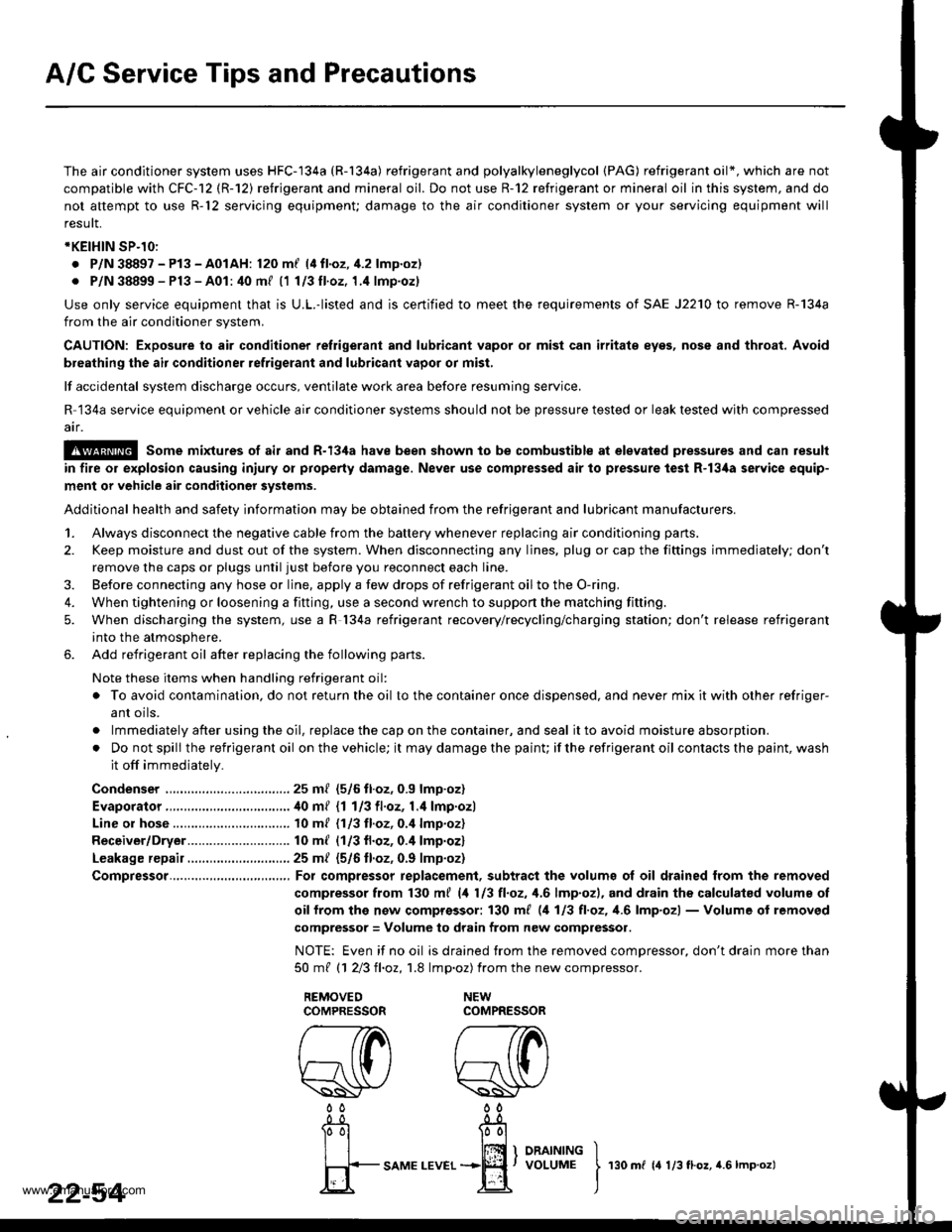
Compressor.......,..., For compressor replacement, subtract the volumg ol oil drained from the removed
compressor from 130 m{ (4 113 tl.oz, 1,6lmp.ozl, and drain the calculatsd volume of
oif from the now comprossor: 130 ml (,1 113 tl,oz, 1.6lmp'ozl - Volume of removed
compressor = Volume to drain from new compressor.
NOTE: Even if no oil is drained trom the removed compressor, don't drain more than
50mt 11 213ll,oz,1.8 lmp.oz) from the newcompressor.
22-54I
rso m r rr:0.o., r.s r-o.o.t
www.emanualpro.com
Page 1152 of 1395

Compressor
Replacement
lf the compressor is marginally operable. run the
engine at idie speed, and let the air conditioner
work for a few minutes. then shut the engine off.
Disconnect the negative cable from the battery.
Recover the refrigerant with a recovery/recycling/
charging station (see page 22-59).
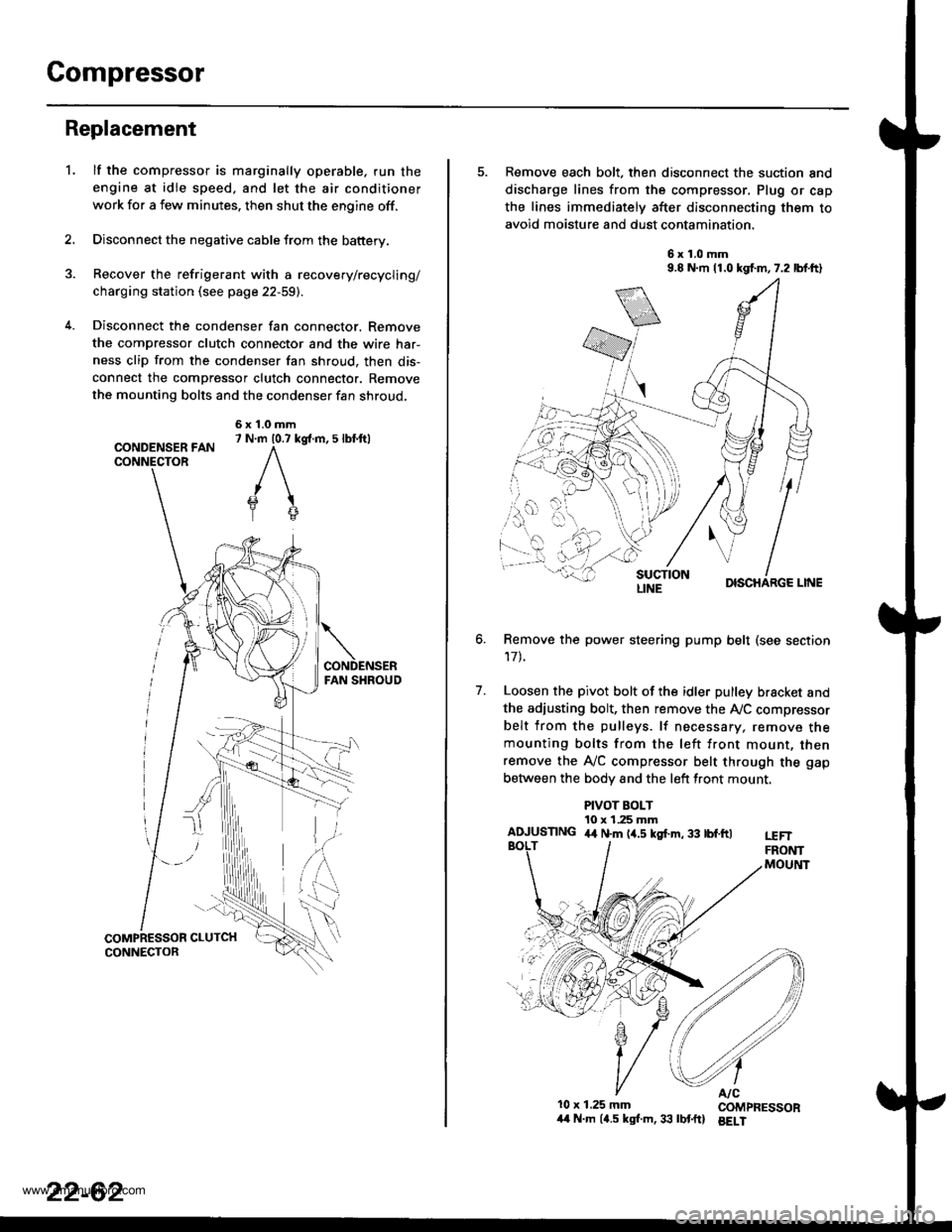
Disconnect the condenser fan connector. Remove
the compressor clutch connector and the wire har-
ness clip from the condenser fan shroud, then dis-
connect the compressor clutch connector. Remove
the mounting bolts and the condenser fan shroud,
CONDENSER FANCONNECTOR
6x1.0mm7 N.m 10.7 kg{.m, 5 lbl.ftl
'L
2.
5. Remove each bolt, then disconnect the suction and
discharge lines from the compressor. Plug or cap
the lines immediately after disconnecting them to
avoid moisture and dust contamination,
6x1.0mm9.8 N.m 11.0 kgf.m,7.2 lbf.ft)
DISCHARGE LINE
Remove the power steering pump belt (see section
17t.
Loosen the pivot bolt of the idler pulley bracket and
the adiusting bolt, then remove the Ay'C compressor
belt from the pulleys. lf necessary, remove themounting bolts from the left front mount, thenremove the A,/C compressor belt through the gap
between the bodv and the left front mount.
6.
7.
PIVOT BOLT10 x 1.25 mmAIUUSTING 4,t N.m (4.5 kgf.m, 33 tbf.ftlt€FTFRONTMOUltlT
10x 1.25 mm COMPRESSOR/t4 N.m (4.5 kgl.m,33 lbtftl BELI
LINE
www.emanualpro.com