Page 944 of 1395

Rear Drum Brakes
Brake Shoes Replacement (cont'd)
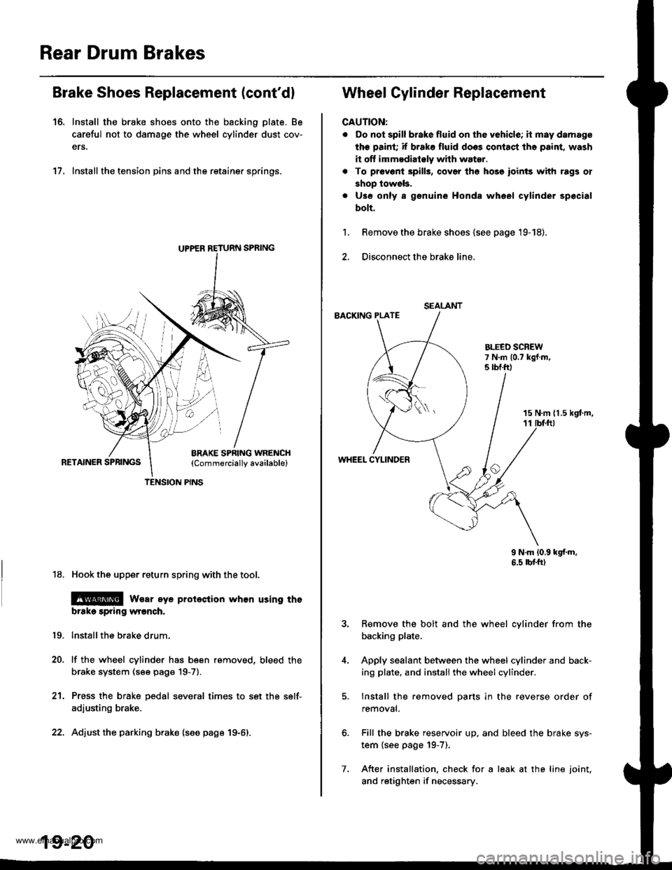
16. Install the brake shoes onto the backing plate. Be
careful not to damage the wheel cylinder dust cov-
ers.
17. Install the tension pins and the retainer springs.
18. Hook the upper return spring with the tool.
@ wsar eye proieclion whon using tho
brtko spring wronch.
lnstallthe brake drum.
lf the wheel cylinder has been removed, bleed the
brake system (see page 19-7).
Press the brake pedal several times to set the self-
adjusting brake.
Adjust the parking brako (see page 19-6).
19.
20.
21.
UPPER RETURN SPRING
TENSION PINS
19-20
7.
SEALANT
Wheel Cylinder Replacement
CAUTION:
. Do not spill brake fluid on th6 vehicle; it may damage
the paint; if brako fluid doos contact tho paint, wash
it off immedialely whh water.
. To pr6v6ni 3pills, cov6r th6 hose ioinls with rags ol
shop lowels,
. Use only a genuine Honda whoel cylinder spocial
bolt.
Remove the brake shoes {see page '19-18).
Disconnect the brake line,
BACKING PLATE
1.
15 N,m 11.5 kgt m,11 tbf.ftl
WHEEL CYLINDER
9 N.m 10,9 kgf'm.6.5 rbtft)
Remove the bolt and the wheel cylinder from the
backing plate.
Apply sealant between the wheel cylinder and back-
ing plate, and install the wheel cylinder.
Install the removed parts in the reverse order of
removal.
Fill the brake reservoir up. and bleed the brake sys-
tem {see page 19-7).
After installation. check for a leak at the line joint.
and retighten if necessary.
www.emanualpro.com
Page 946 of 1395

Brake Hoses/Lines
Hose Replacement
CAUTION: Do not spill brak€ fluid on the vehicl€; it m8y
damage th€ paint; if brak€ lluid doos contact tho paint,
wash it off immediately with water.
NOTE:
. Before reassembling, check that all pans are free of
dust and other foreign particles.
. Replace parts with new ones whenever specified to
qo so,
Replace the brake hose ifthe hose is twisted, cracked.
or if it leaks.
Disconnect the brake hose from the brake line using
a 10 mm flare nut wrench.
'1.
FLARE NUTWRENCH(Commercially
available)
BRAKE HOSE
Remove and discard the brake hose cliD from the
brake hose.
Remove the banjo bolt, and disconnect the brake
hose from the calioer.
5. Remove the brake hose from the knuckle.
19-22
6. Install the brake hose on the knuckle first, then con-
nect the brake hose to the caliper with the banjo bolt
and new sealing washers.
6 mm HOSE BRACKETEOLTS9.8Nm(1.0 kgf.m,7 lbf.ftlBRAKE HOSE
BANJO BOLT34 N.m
13.5 kgf.m, 25 lbl.ftl
SEALING WASHERSHeplace.
7. Installthe brake hose on the upper brake hose bracket
with a new b.ake hose clip.
Replace.
BRAKE HOSE ARACKET
Connect the brake line to the brake hose.
After installing the brake hose, bleed the brake sys-
tem (see page '19-7).
Perform the following checks;
. Check the brake hose and line joint for leaks, and
tighten if necessary.
. Check the brake hoses for interference and twist-
Ing
1 tbtftl
F
)
/
8.
9.
www.emanualpro.com
Page 979 of 1395

Modulator Unit
Removal/lnstallation
NOTE:
. Do not spill brake fluid on the vehicle; it may damage the painu if brake fluid does contact the paint, wash it off imme-
diately with water.
a Take care not to damage or deform the brake lines during removal and installation.
. To prevent the brakefluidfrom flowing, plug and coverthe hose ends and joints with a shop towel or equivalent mate-
rial,
Romoval
1. Disconnect the modulator unit and Dump motor connectors.
2. Disconnect the brake lines, then remove the modulator unit.
lnstallation
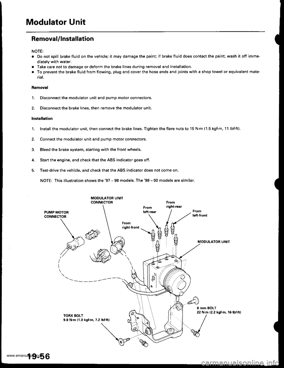
1. Install the modu lator u nit. then con nect the brake lines. Tighten the flare nuts to 15 N.m ( 1.5 kgf.m, 1 1 lbf.ft).
2. Connect the modulator unit and oumo motor connectors.
3. Bleed the brake system, staning with the front wheels.
4. Start the engine, and check that the ABS indicator goes off.
5. Test-drive the vehicle, and check that the ABS indicator does not come on,
NOTE: This illustration shows the '97 - 98 models. The'99 - 00 models are similar.
PUMP MOTORCONNECTOR
MODULATON UNIT\*\
,@
I
TORX EOLT9.8 N,m (1.0 kgf.m.7.2lbf ftl
19-56
www.emanualpro.com
Page 1148 of 1395

A/C System Service
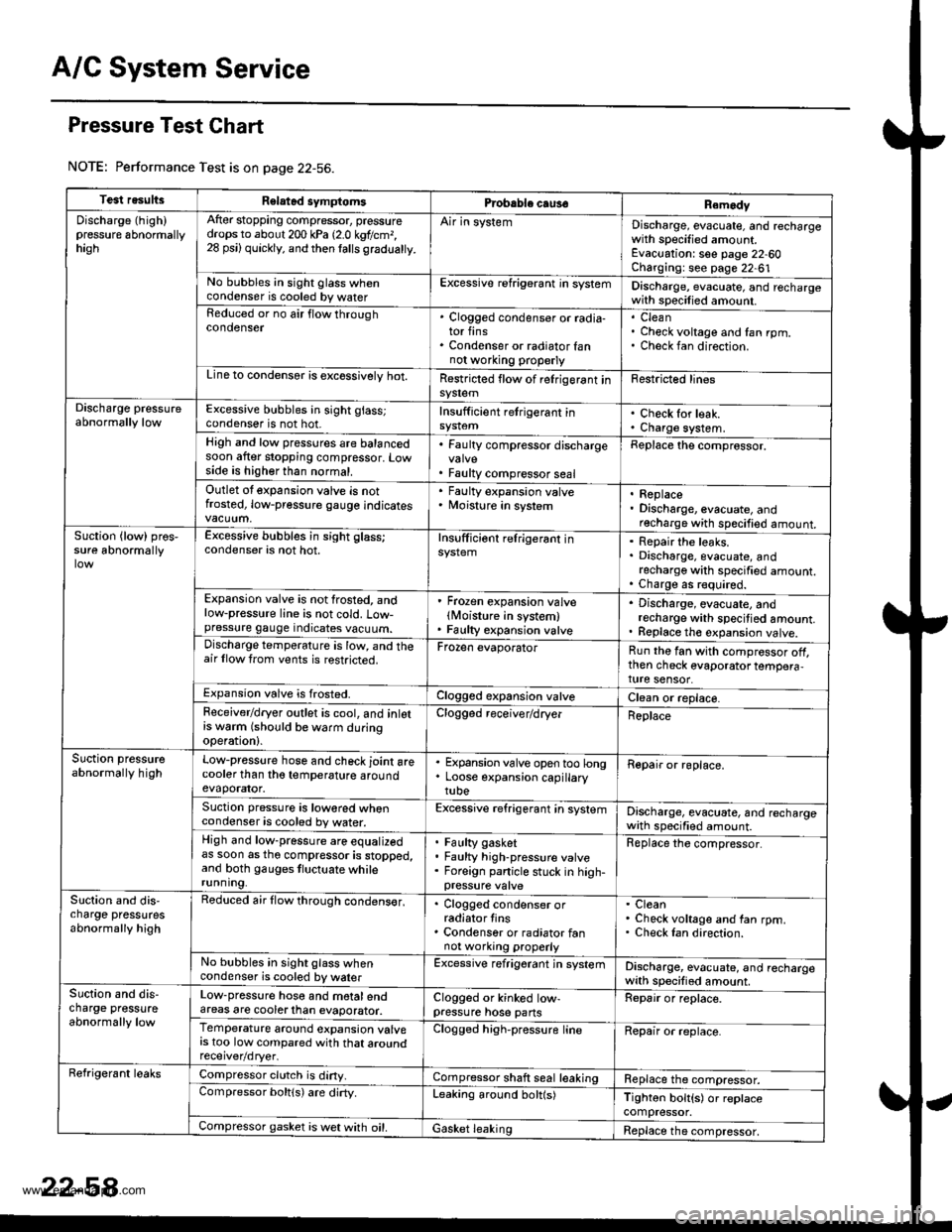
Pressure Test Chart
NOTE: Performance Test is on page 22-56.
Test resultsRelatad symptomsPrcbable caus€Remody
Discharge (high)pressure 6bnormallyhagh
After stopping compressor, pressuredrops to about 200 kPa 12.0 kgtlcm,,28 psi) quickly, and then lalls gradualty.
Air in systemDischarge, evacuate, and rechargewith specified amount.Evacuation: see page 22-60Charging: see page 22-61No bubbles in sight glass whencondenser is cooled by waterExcessive refrigerant in systemDischarge, evacuate, and rechargewith specilied amount.Reduced or no air flow throughcondenser. Clogged condenser or radia-tor fins. Condenser or radiator fannot wo.king properly
CleanCheck voltage and fan rpm.Check fan direction.
Line to condensor is excossivelv hot.Restricted flow of relrigerant insy$emFestricted lines
Discharge pressureabnormally lowExcessive bubbles in sight glass;condenser is not hot.Insufficient retrigerant inCheck for leak.Charge system.High and low pressures are balancedsoon after stopping compressor. Lowside is higher than normal.
. Faulty compressor discharge
. Faulty compressor seal
Replace the comprossor.
Outlet ot expansion valve is notfrosted, low-pressure gauge indicates
' Faulty expansion valve. Moisture in system. Replace. Discharge, evacuate, andrecharge with specified amount.Suction {low) pros,sure abnormallyExcessive bubbles in sight glass;condenser is not hot.Insufficiont relrigerant inRepair the leaks.Discharge, evacuate, andrecharge with specified amount.Charge as r€quired.Expansion valve is not frosted, andlow-pressure line is not cold. Low-pressure gauge indicates vacuum.
' Frozen expansion valvelMoisture in system). Faulty expansion valve
. Discharge, evacuate, andrecharge with specitied amount.. Replace th€ expansion valve.Discharge temperature is low, and theair llow trom vents is restricted.Frozen evaporatorRun the fan with compressor off,then check evaporator tempera,ture sensor.Expansion valve is frosted.Clogged expansion valveClean or replace.Feceiver/dryer outlet is cool, and inlotrs w6rm (should be warm duringoperation).
Clogged receiver/dryerReplace
Suction pressureabnormally highLow-pressure hose and check joint arecooler than tho temperature aroundevaporator.
. Expansion valve open too long. Loose expansion capillarytube
Repair or roplace.
Suction pressure is lowored whencondenser is cooled by water.Excessive refrigerant in systemDischarge, evacuate, and rechargewath specified amount.High and low-pressure are equalizedas soon as tho compressor is stopped,and both gauges tluctuate whilerunning.
Faulty gasketFaulty high-pressure valveForeign panicle stuck in high-
Replace the compressor.
Slction and dis,charge pressutesabnormally high
Reduced air flow through condens€r,. Clogged condenser orradiator tins. Condenser or radiator fannot working properly
CleanCheck voltage and fan rpm.Check Ian direction.
No bubbles in sight glass whencondenser is cooled by walerExcessive refrigerant jn systemDischarge, evacuate, and rechargewith specified amount.Suction and dis-charge pressureabnormally low
Low-pressure hose and motalendareas are cooterlhan evaporator.Clogged or kinked low-pressure hose pansRepair or replace.
Temperature around expansion valvers too low compared with that aroundClogged high-pressure lineRepair or replace.
Refrigerant leaksCompressor clutch is diny.Compressor shaft seal leakingReplace the compressor.Compressor boltls) are dirty.Leaking around bolt(s)Tighton bolt{s) or replacecompressor.Compressor gasket is wet with oil.Gasket leakingReplace the compressor,
www.emanualpro.com