Page 460 of 1395
Shift Fork Assembly
Disassembly/ReassemblY
I erior,o reassembling, clean all the pans in solvent, dry them, and apply lubricant to any contact parts
1ST/2ND SHIFT FORK
SHIFT PIECE
PIN PUNCH, 5.0 mm
3RD/,|TH SHIFT FoRK
5TH/REVERSE
13-21
www.emanualpro.com
Page 461 of 1395

Shift Fork Assembly
Clearance Inspection
NOTE: The synchro sleeve and synchro hub should be
reolaced as a set.
1. Measure the clearance between each shift fork and
its matching synchro sleeve.
Standard: 0.35 - 0.65 mm 10.01/t - 0.026 inl
Service Limit: 1,0 mm {0.039 inl
SHIFT FORK
2. lf the clearance exceeds the service limit. measure
the thickness of the shift fork fingers.
Standard:
lf the thickness of the shift fork finger is less than
the standard, replace the shift fork with a new
one.
lf the thickness of the shift fork tinger is within
the standard, replace the synchro sleeve with a
new one.
3rd/4th shift fork7.4 - 7.6 mm
(0.29 - 0.30 in)
1sv2nd shift fork
5th shift fork
6.2 - 6.4 mm(0.24 - 0.25 in)
3. Measure the clearance between the shift fork and
the shift arm A.
Standard; 0.2 - 0.5 mm (0.008-0.020 in)
Service Limit: 0.6 mm (0.02i1 in)
sTH/REVERSESHIFT PIECE ran,rru
lST/2NDSI{IFT FORK
lf the clearance exceeds the service limit, measure
the width of the shift arm A.
Standard: 12.9 - 13.0 mm 10.508 - 0.512 inl
lf the width of the shift arm A is less than the
standard, reDlace the shift arm A with a new one.
lf the width of the shift arm A is within the stan-
dard, replace the shift fork or shift piece with a
new ones.
www.emanualpro.com
Page 506 of 1395
Transmission Assembly
Reassembly
1. Install the differential assembly in the clutch hous-
Ing.
Install the spring washer and washer with the angle
against the clutch housing as shown.
Tape the mainshaft splines. insert the mainshaft
and countershaft into the shift forks, and install
them as an assemblv.
Tape the mainshattsplines.
DIFFERENTIAL ASSEMBLY
4. '97 - 99 models: Install the reverse idle gaar and
reverse gear shaft in the clutch
housing.'00 model: Install the coller, thrust washer, reverse
idler gear and the reverse gear shaft in
the clutch housing.
THRUST WASHER
COLLER
NOTE: Install the reverse gear shaft ('00 model) in
the direction shown.
5. Install the reverse shift holder in the clutch housing
with the sth/reverse shift piece pin positioned in the
slot of the reverse shift fork.
5x1.0mm15 N'm 11.5 kgt.m, 11 lbf.ftl
model
REVERSE SHIFT HOLDER
(cont'd)
13-67
www.emanualpro.com
Page 508 of 1395

12. Apply liquid gasket to the surface of the transmis-
sion housing as shown.
Note these items:
. Use liquid gasket (P/N 08718 - 0001 or 08718 -
0003).
. Remove the dirty fluid from the sealing surface.
. Seal the entire circumterence of the bolt holes to
prevent fluid leakage.
. lf 20 minutes have passed after applying liquid
gasket, reapply it and assemble the housings.
a Allow it to cure at least 20 minutes after assem-
bly betore filling the transmission with MTF.
Install the 14 x 20 mm dowel pins.
Set the stopper ring as shown. Place the transmis-
sion housing over the clutch housing, being careful
to line up the shafts. Be sure to align the stop ring
with the 5th shift fork finger tip.
r3.
14.
TRANSMISSION HOUSING
SHIFT FORK
vk..*,
Align point
17.
the 32 mm sealing bolt.
15. Lower the transmission housing with the snap ring
pliers. and set the snap ring into the groove of the
countershaft bearing.
Check that the snap ring is securely seated in the
groove of the countershaft bearing.
Dimension A as installod: 3.6 - 6.3 mm
(0.142 - 0.2/8 in)
16.
32 mm SEALING BOLT25 N m 12.5 kgf.m, 18 lbf.ftlSNAP RING
(cont'd)
13-69
Apply liquid gasket (P/N 08718 - 0001 or 08718 -
0003) to the 32 mm sealing bolt threads, then install
SNAP RING PLIERS
DOWEL PINS
www.emanualpro.com
Page 530 of 1395

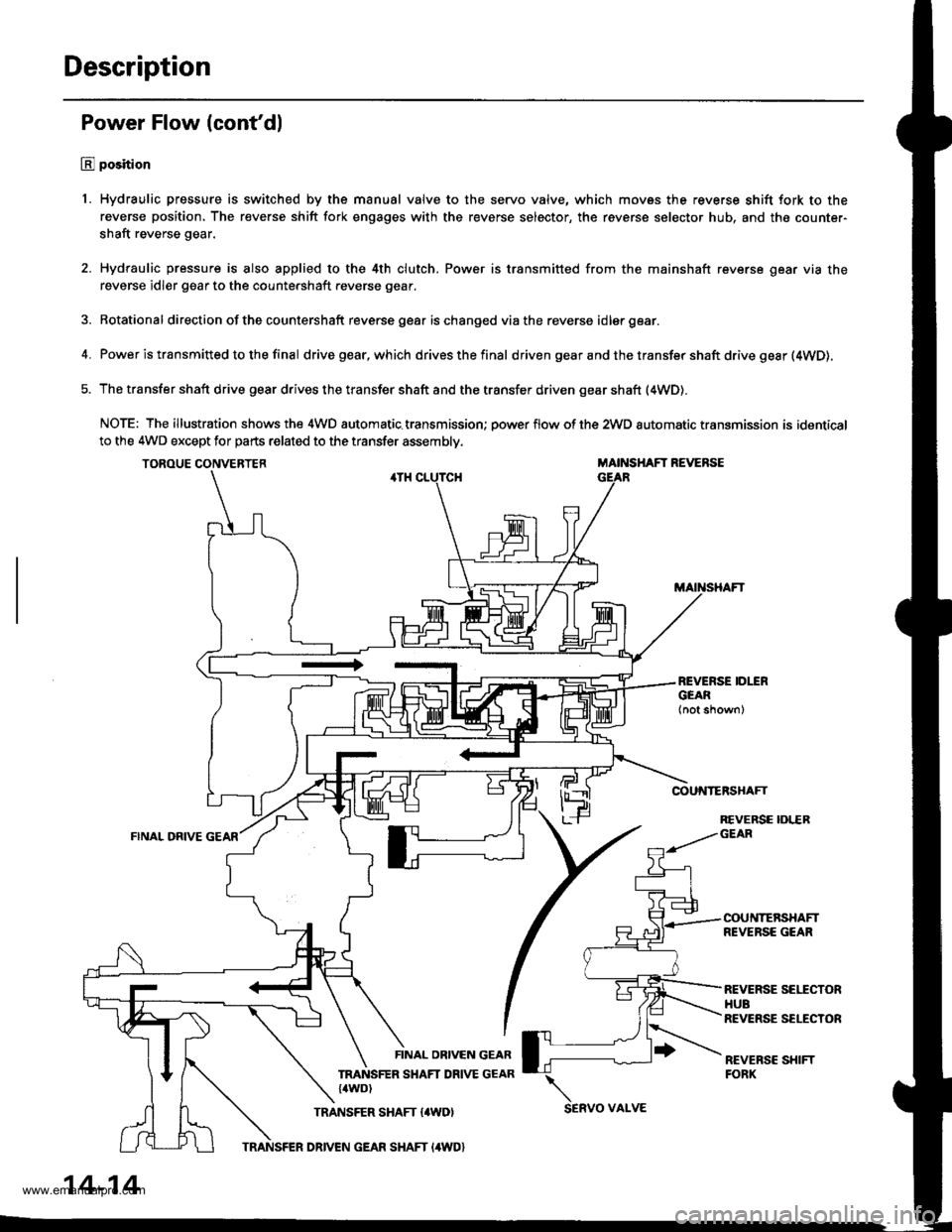
Description
Power Flow (cont'dl
E position
1. Hydraulic pressure is switched by the manual valve to the servo valve, which movss the reverse shift fork to the
reverse position, The reverse shift fork engages with the reverse selector, the reverse selector hub, and the counter-
shaft reverse gear.
2. Hydraulic pressure is also applied to the 4th clutch. Power is transmitted from the mainshaft reverse gear via the
reverse idler gear to the countershaft reverse gear.
3. Rotational direction ofthe countershaft reverse gear ischanged viathe reverse idlergear.
4. Power is transmitted to the final drivegear,which drivesthefinal d riven gear a nd the transfer shaft drive gesr (4WD).
5. The transfer shaft drive gear drives the transfer shaft and the transfer driven gear shaft (4WD).
NOTE: The illustration shows the 4WD automatic.transmission; power flow of the 2wD automatic transmission is identical
to the 4WD except for parts related to the transfer assembly.
TOROUE CONVERTERMAINSHAFT REVERSE
COUNTERSHAFT
FINAL ORIVE
REVERSE IDLERGEAR
COUNTERSHAFTREVERSE GEAR
REVERSE SEITCTORHUBREVERSE SELECTOR
REVEBSC SHIFTFORK
FINAL OBIVEN GEAR
TRANSFER SHAFT DRIVE GEAR{4WD)
TRANSFER SHAFT {4WD)SERVO VAI-VE
14-14
TRANSFER DRIVEN GEAR SHAFT I4WD}
www.emanualpro.com
Page 544 of 1395
Description
Hydraulic Control (cont'd)
Servo Body
The servo body is located on the secondary valve body. The servo body contains the servo valve (which is integrated withthe reverse shift fork), and the accumulators.
2ND ACCUMULATOR
3RD SUBACCUMULATOR
SERVO BODY
1ST ACCUMULATOR
SERVO VALVE/SHIFTFORK SHAFT
14-28
www.emanualpro.com
Page 671 of 1395

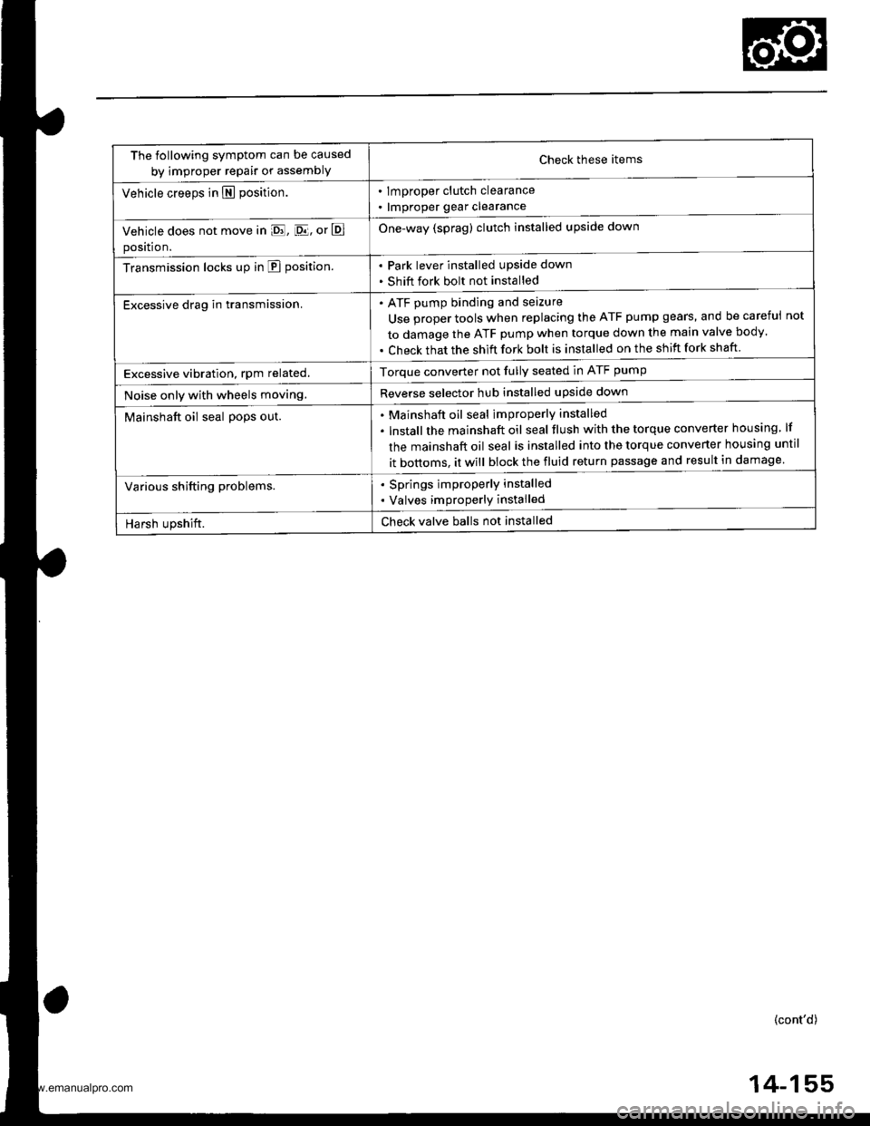
The following symptom can be caused
by improper repair or assemblYCheck these items
. lmproper clutch clearance
. lmproper gear clearance
One-way (sprag) clutch installed upside down
Park lever installed upside down
Shift fork bolt not installed
Vehicle creeps in N position.
Vehicle does not move in E, [D.lj, or E
position.
Transmission locks up in E position.
Excessive drag in transmission.ATF pump binding and seizure
Use proper tools when replacing the ATF pump gears, and be careful
to damage the ATF pump when torque down the main valve body.
Check that the shift fork bolt is installed on the shift fork shaft
not
Excessive vibration, rpm related.Torque converter not fully seated in ATF pump
Reverse selector hub installed upside downNoise only with wheels moving.
Mainshaft oil seal po9s out.Mainshaft oil seal improperly installed
lnstallthe mainshaft oil seal tlush with the torque converter housing lf
the mainshaft oil seal is installed into the torque converter housing until
it bottoms. it will block the fluid return passage and result in damage
Various shifting problems.. Springs improperly installed
. Valves improperly installed
Harsh upshift.Check valve balls not installed
(cont'd)
4-155
www.emanualpro.com
Page 672 of 1395

Symptom-to-Com ponent Chart
Hydraulic System (cont'd)
NOTES
See flushing procedure, page l4-264 and 265,
BSet idle rpm in gear to specified idle speed. lf still no good, adjust motor mounts as outlined in enginesection of this manual.
clf the large clutch piston O-ring is broken, inspect the piston groove for rough machining.
Dlf the clutch pack is seized or is excessively worn. inspect the other clutches fot wear, and check the orificecontrol valves, CPC valve, and linear solenoid for free movement.
lf the linear solenoid is stuck, inspect the clutches for wear.
lf the 1-2 shift valve is stuck closed. the transmission will not upshift. lf stuck open, the transmission hasno lst gear.
Hlf the 2nd orifice control valve is stuck, inspect the 2nd and 3rd clutch Dacks for wear.
lf the 3-4 orifice control valve is stuck, inspect the 3rd and 4th clutch packs for wear.
Jlf the clutch pressure control valve is stuck closed. the transmission will not shift out of lst gear.
Klmproper alignment of main valve body and torque converter housing may cause ATF pump seizure. Thesymptoms are mostly an rpm-related ticking noise or a high-pitched squeak.
Llf the ATF strainer is clogged with particles of steel or aluminum, inspect the ATF pump and differentialpinion shaft. lf both are OK and no cause for the contamination is found, replace the torque converter.
Mlf the lst clutch feed pipe guide in the end cover is scored by the mainshaft. inspect the ball bearing forexcessive movement in the transmission housing. lf oK, replace the end cover as it is dented. The o-rinounder the guide is probably worn.
N' Replace the mainshaft if the bushing for the 4th feed pipe is loose or damaged, lf the 4th feed pipe is darrFaged or out of round. replace the end cover.' Replace the mainshaft if the bushing for the l st feed pipe is loose or damaged. lf the 1st feed pipe is dam-aged or out of round, replace it.
oA worn or damaged sprag clutch is mostly a result of shifting the transmission in E!. E, or E positionwhile the wheels rotate in reverse. such as rocking the vehicle in snow.
PInspect the frame for collision damage.
lnspect for damage and wear:
l. Reverse selector gear teeth chamfers.
2. Engagement teeth chamfers of countershaft 4th and reverse gear.
3. Shift fork for scuff marks in center.
4. Differential pinion shaft for wear under pinion gears.
5. Bottom of 3rd clutch for swirl marks.
Replace items 1, 2, 3. and 4 if worn or damaged. lf transmission makes a clicking, grinding, or whirring noise,also replace mainshaft 4th gear, reverse idler gear, and countershaft 4th gear in addition to 1,2, 3, or 4.lf differential pinion shaft is worn, overhaul differential assembly, replace ATF strainer, and thoroughly cjeantransmission, flush torque converter. cooler, and lines,lf bottom of 3rd clutch is swirled and transmission makes gear noise. replace the countershaft and final drivenoear,
Be very careful not to damage the torque converter housing when replacing the main ball bearing. you
may also damage the ATF pump when you torque down the main valve body. This will result in ATF pumpseizure if not detected. Use the Drooer tools.
SInstall the main seal flush with the torque converter housing. lf you push it into the torque converterhousing until it bottoms out, it will block the fluid return passage and result in damage.
www.emanualpro.com