2000 HONDA CR-V RPM
[x] Cancel search: RPMPage 63 of 1395
,r1.?
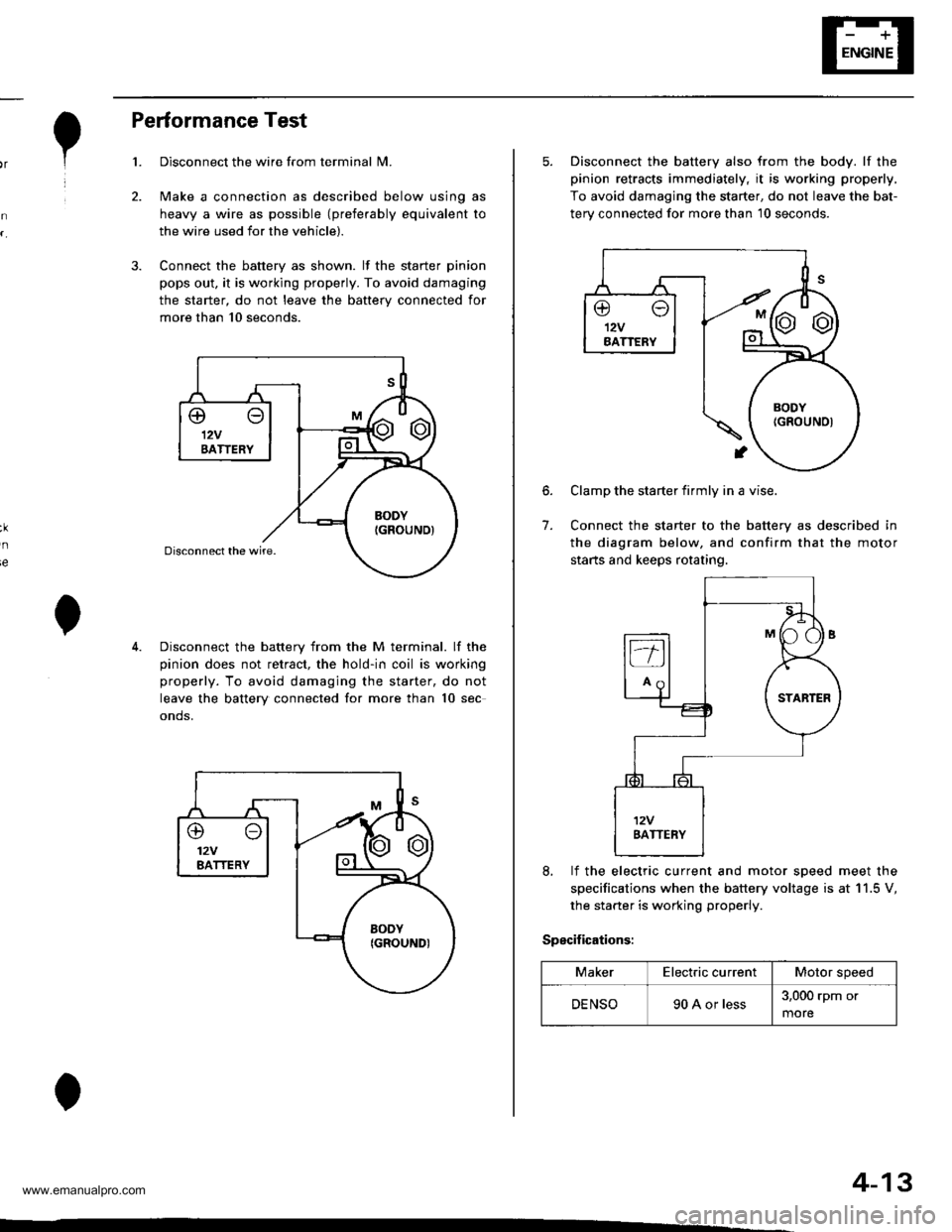
Performance Test
Disconnect the wire from terminal N4.
Make a connection as described below using as
heavy a wire as possible (preferably equivalent to
the wire used for the vehicle).
Connect the battery as shown. lf the starter pinion
pops out. it is working properly. To avoid damaging
the starter, do not leave the battery connected for
more than 10 seconds.
3.
ie
Disconnect the battery from the M terminal. lf the
pinion does not retract, the hold-in coil is working
properly. To avoid damaging the starter, do not
leave the battery connected for more than 10 sec
onds.
@o12VBATTERY
4-13
5. Disconnect the battery also from the body. lf the
pinion retracts immediately, it is working properly,
To avoid damaging the starter, do not leave the bat-
terv connected for more than 10 seconds.
6.
7.
Clamp the starter firmly in a vise.
Connect the starter to the battery as described in
the diagram below, and confirm that the motor
starts and keeps rotating.
8, lf the electric current and motor soeed meet the
specifications when the battery voltage is at 11.5 V,
the starter is working properly.
Specifications:
MakerElectric currentMotor speed
DENSO90 A or less3,000 rpm or
more
www.emanualpro.com
Page 66 of 1395

lgnition System
5.
lgnition Timing Inspection and Setting
2.
1.Check the idle speed, and adjust it if necessary (see
section 1 1).
Pull out the service check connector 2P (BRN and
BLK wires) from the connector holder located under
the dash on the front passenger side, then connect
the scs service connector (P/N 07PAz - 0010100) to
it.
Start the engine. Hold the engine at 3,000 rpm with
no load (A/T in N or E, Mff in neutral) until the
radiator fan comes on, then let it idle.
Connect the timing light to the No. I ignition wire,
then point the light toward the pointer on the timing
belt cover.
Check the ignition timing in no load conditions:
headlights, blower fan, rear window defogger, and
air conditioner are not operating.
lgnition Timing:
M/T: 16" 12" BTDC (RED) idling in neutral
AlTt'16" !2" BTDC (RED) idling in E or E
CRANKSHAFTPULLEY
4-16
6. lf necessary, adjust the ignition timing as follows.
Loosen the distributor mounting bolts, and turn the
distributor ignition (Dl) housing counterclockwise to
advance the timing or clockwise to retard the tim-
t no,
7.
8.
MOUNTING BOLTS24 N.m {2.4 kgf m, 17 lbtft}
Tighten the distributor mounting bolts, and recheck
the ignition timing.
Disconnect the SCS service connector from the ser-
vice check connector.
To RETARD
www.emanualpro.com
Page 78 of 1395
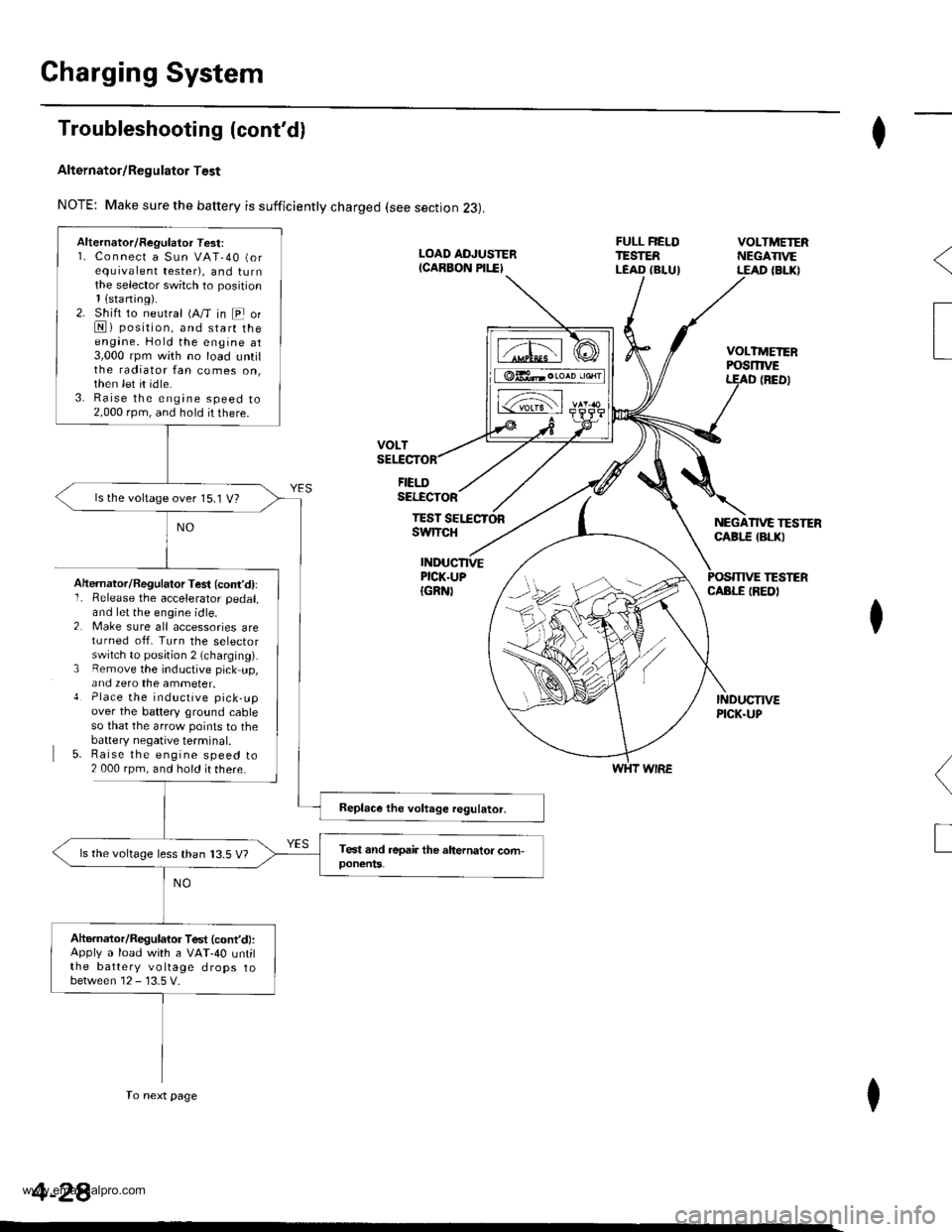
Gharging System
Troubleshooting (cont'd)
Alternator/Regulator Test
NOTE: Make sure the battery is sufficiently charged (see section 23).
FIELDSELECTOR
TESTswtTcH
I
VOLTMEIERPOSmVEt
NEGATIVE TESTERCABI.E {BLKI
(BED)
TESTERINDUCTIVEPICK.UP{GRN)CABLE IREDIAhernator/Regulator Test (cont'd)lI� Release the accelerator pedal,and let the engine idle.2 Make sure all accessories areturned off. Turn the selectorswitch to posjtion 2 (charging).3 Remove the inductive pick up,and zero the ammeter.{ Place the inductive pick-upover the battery ground cableso that the arrow points to thebaftery negative terminal.5. Raise the engine speed to2 000 rpm, and hold ir there.
I
(
T
I
WHT WIRE
Alternator/Regulator Test:1. Connect a Sun VAT-40 (orequrvalent tester), and turnthe selector switch to position1{sraning).2. Shift to neutral (A/T in E orN) position, and start theengane. Hold the engine at3,000 rpm with no load untilthe radiator fan comes on,then let it idle.3. Raise the engine speed to2,000 rpm, and hold it there.
ls the voltage over 15.1 V?
ls the voltage less than 13.5 V?
Altarnator/Regulator Test (cont'd:Apply a load with a VAT-40 untilthe battery voltage drops tobetween 12 - 13.5 V.
To next page
4-28
www.emanualpro.com
Page 93 of 1395
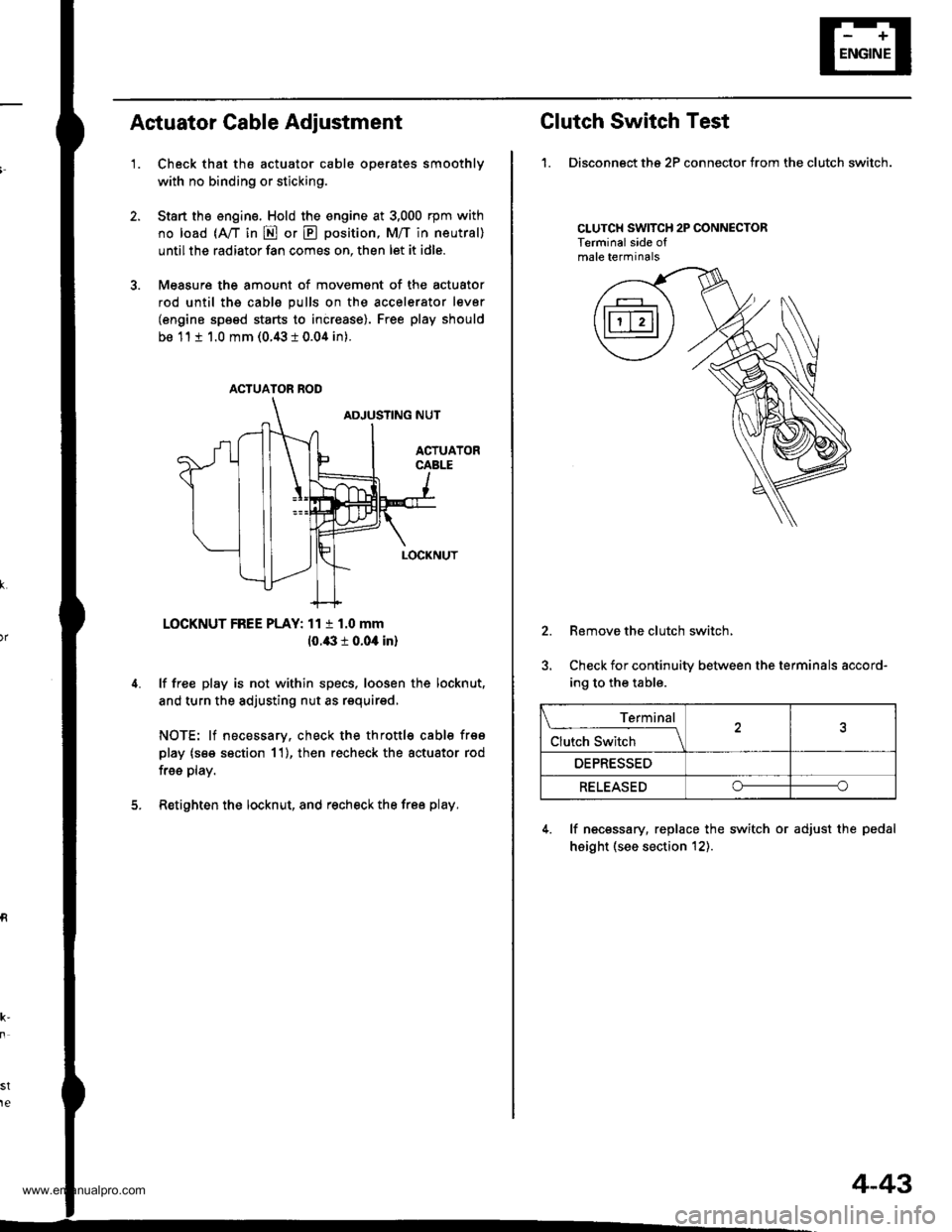
Actuator Cable Adiustment
'1.Check that the actuator cable operates smoothly
with no binding or sticking.
Start the engine. Hold the engine at 3,000 rpm with
no load (A,/T in E or E position, M/T in neutral)
until the radiator fan comes on, then let it idle.
Measure the amount of movement of the actuator
rod until ths cable pulls on the accelerator lever
(engine speed starts to increase). Free play should
be 11 t 1.0 mm (0.43 i 0.04 in).
LOCKNUT FREE PLAY: 11 t 1.0 mm
10.43 r 0.04 in)
lf free play is not within specs, loosen the locknut,
and turn the adjusting nut as requirsd,
NOTE: lf necessary, check the throttl€ cable frso
play (s€e section 11), then recheck the actuator rod
free play.
Retighten the locknut, and recheck the free play.
st
te
ACTUATOR ROD
Clutch Switch Test
1. Disconngct ths 2P connector from the clutch switch.
CLUTCH SWITCH 2P CONNECTORTerminalside ofmale terminals
2.
5.
Remove the clutch switch,
Check for continuity between the terminals accord-
ing to the table.
4. lf necessary, replace the switch or adjust the pedal
height (see section t2).
Terminal
Clutch Switch \
OEPRESSED
RELEASEDoo
4-43
www.emanualpro.com
Page 177 of 1395
Oil Pressure SwitchOil Pressure
Testing
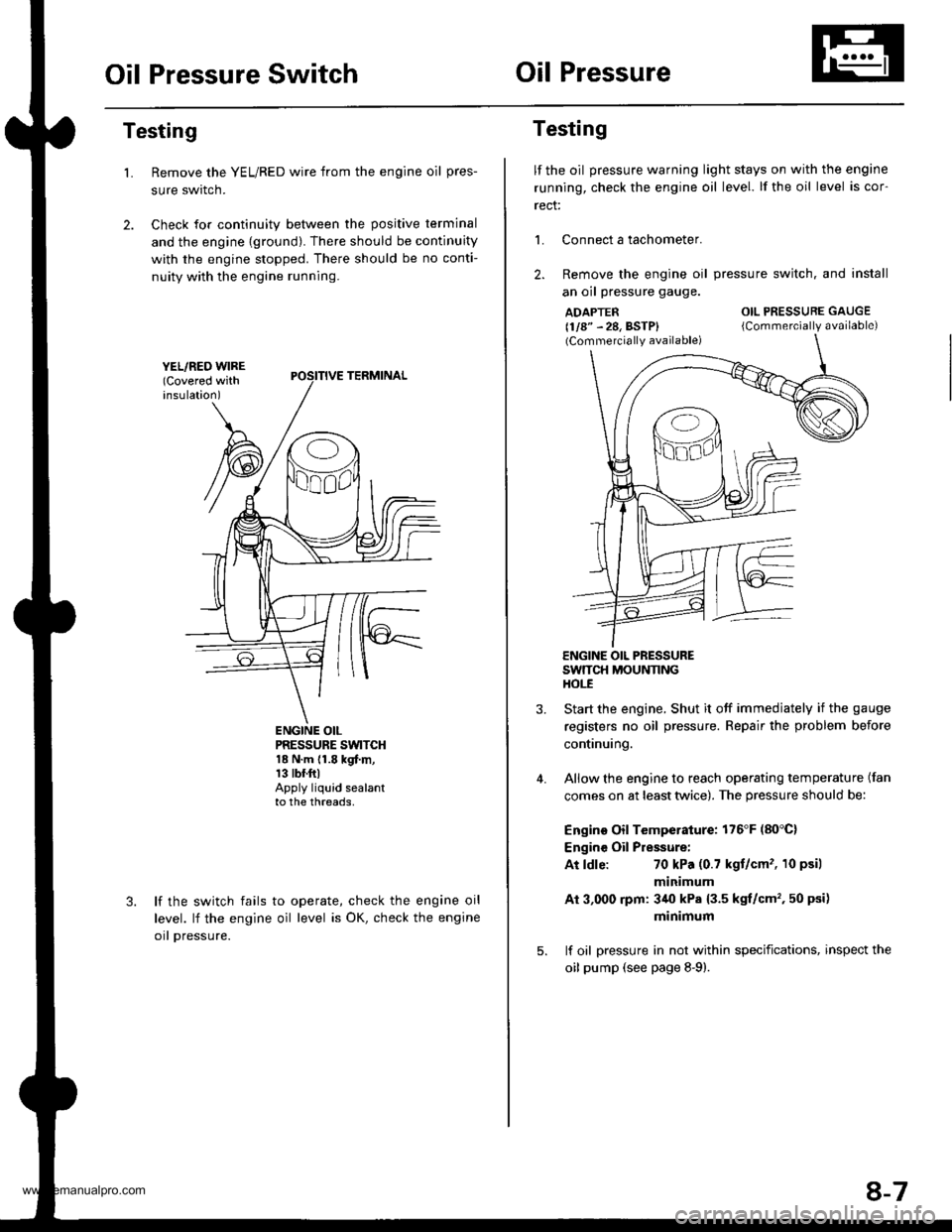
Remove the YEL/RED wire from the engine oil pres-
sure swrtcn.
Check for continuity between the positive terminal
and the engine {ground). There should be continuity
with the engine stopped. There should be no conti-
nuity with the engine running.
L
PRESSURE SWTCH18 N.m {1.8 kgf.m,13 tbr.ftlApply liquid sealantto the threads,
lf the switch fails
level. lf the engine
orl pressure.
to operate, check the engine oil
oil level is OK, check the engine
Testing
lf the oil pressure warning light stays on with the engine
running, check the engine oil level. lf the oil level is cor-
rect:
L Connect a tachometer.
2. Remove the engine oil
an oil pressure gauge.
ADAPTER(1/8" - 28, BSTP)(Commercially available)
pressure switch. and install
OIL PRESSURE GAUGE
{Commercially available)
4.
ENGINE OIL PRESSURESWTTCH MOUNNNGHOt-E
Start the engine. Shut it off immedjately if the gauge
registers no oil pressure. Repair the problem before
continuing.
Allow the engine to reach operating temperature (fan
comes on at least twice). The pressure should be:
Engino Oil Temperature: 176'F (80'C)
Engine Oil Pressure:
At ldle:70 kPa (0.7 kgt/cm'�, 10 psil
minimum
Ai 3,000 rpm: 3/r0 kPa {3.5 kgt/cm', 50 psi)
minimum
lf oil pressure in not within specifications, inspect the
oil pump (see page 8-9).
8-7
www.emanualpro.com
Page 267 of 1395
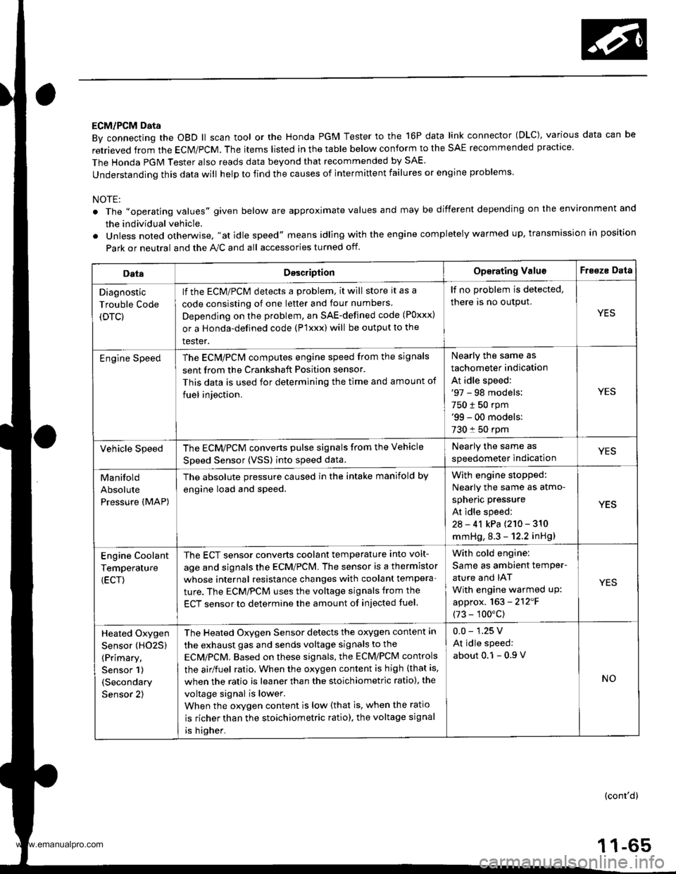
ECM/PCM Data
By connecting the OBD ll scan tool or the Honda PGM Tester to the 16P data link connector (OLC), various data can be
retrieved from the ECM/PCM. The items listed in the table below conform to the SAE recommended practice
The Honda PGM Tester also reads data beyond that recommended by SAE.
understanding this data will help to find the causes of intermittent failures or engine problems.
NOTE:
The ',operating values" given below are approximate values and may be different depending on the environment and
the individual vehicle.
Unless noted otherwise. "at idle speed" means idling with the engine completely warmed up, transmission in position
Park or neutral and the A,./C and all accessories turned otf.
DataDesc.iptionOp€rating ValuoFreeze Data
Diagnostic
Trouble Code
(DTC)
lf the ECM/PCM detects a problem, it will store it as a
code consisting of one letter and tour numbers
Depending on the problem, an SAE-defined code (Poxxx)
or a Honda-defined code (P'lxxx) will be output to the
tester.
lf no problem is detected,
there is no output.
YES
Engine SpeedThe ECN4/PCN4 computes engine speed from the signals
sent from the Crankshaft Position sensor.
This data is used for determining the time and amount of
fuel iniection.
Nearly the same as
tachometer indication
At idle speed:'97 - 98 models:
750 t 50 rpm'99 - 00 models:
730 f 50 rpm
YES
Vehicle SpeedThe ECM/PCM converts pulse signals from the Vehicle
Speed Sensor (VSSI into speed data.
Nearly the same as
speedometer indicationYES
Manifold
Absolute
Pressure (MAP)
The absolute pressure caused in the intake manifold by
engine load and speed.
With engin6 stopped:
Nearly the same as atmo-
spheric pressure
At idle speed:
2a - 41 kPa {210 - 310
mmHg, 8.3 - 12.2 inHg)
YES
Engine Coolant
Temperature
{ECT)
The ECT sensor converts coolant temperature into volt-
age and signals the ECM/PCM. The sensor is a thermistor
whose internal resistance changes with coolant tempera-
ture. The ECM/PCM uses the voltage signals from the
ECT sensor to determine the amount of injected fuel
With cold engine:
Same as ambient temPer-
ature and IAT
With engine warmed uP:
approx. 163 - 2'12'F
(73 - 100"c)
YES
Heated Oxygen
Sensor (HO25)
(Primary,
Sensor 1)
(Secondary
Sensor 2)
The Heated Oxygen Sensor detects the oxygen content in
the exhaust gas and sends voltage signals to the
ECMiPCM. Based on these signals, the ECM/PCM controls
the airlfuel ratio. When the oxygen content is high (that is.
when the ratio is leaner than the stoichiometric ratio), the
voltage signal is lower.
When the orygen content is low (that is, when the ratio
is richer than the stoichiometric ratio), the voltage signal
is higher.
0.0 - 1.25 V
At idle speed:
about 0.1 - 0.9
NO
(cont'd)
1 1-65
www.emanualpro.com
Page 268 of 1395

Troubleshooting
Troubleshooting Procedures (cont'd)
DataDescliptionOperating ValueFreezo Data
HO2S
Feedback
Loop Status
Loop status is indicated as "open" or "closed".
Closed: Based on the HO2S output, the ECM/pCM deter-mines the airlfuel ratio and controls the amount ofinjected fuel.
Open: ignoring HO2S output, the ECM/pCiM refers to sig,nals from the TP, MAP, and ECT sensors to control theamount of injected fuel.
At idle speed: closed
YES
Short Term
Fuel Trim
The airlfuel ratio correction coefficient for correcting theamount of injected fuel when HO2S feedback is in theclosed loop status. When the signal from the HO2S isweak, short term fuel trim gets higher, and the ECM/PCMincreases the amount of injected fuel. The airlfuel ratiogradually gets richer, causing a higher HO2S output.Consequently. the short term fuel trim is lowered. andthe ECM/PCM reduces the amount of injected fuel.This cycle keeps the airfuel ratio close to the stoichio-metric ratio when in closed looD status.
t:20y"
YES
Long Term
Fuel Trim
Long term fuel trim is computed from shon term fueltrim and indicates changes occuring in the fuel supplysystem over a long period.
lf long term fuel trim is higher than 1,00. the amount ofinjected fuel must be increased. lf it is lower than L00.the amount of injected fuel must be reduced.
! 20%
Intake Air
Temperature
(IAT)
The IAT sensor converts intake air temperature into volt-age and signals the ECrU/PCM. When intake air tempera-ture is low, the internal resistance of the sensorincreases, and the voltage signal is higher.
With cold engine:
Same as ambient temper-
ature and ECTYES
Throttle
Position
Based on the accelerator pedal position, the openingangle of the throttle valve is indicateo.At idle speed:
approx. 10%
lgnition
Timing
lgnition timing is the ignition advance angle set by theECM/PCM. The ECM/PCM matches ignition timing to thedriving conditions.
At idle speed: 16'1 4.
BTDC with the SCS ser-
vtce connector connected.
NO
Calculated
Load Value(cLV)
CLV is the engine load calculated from the MAp data.At idle speed:
2A - 410/o
At 2,500 rpm with no load:
13 - 260/o
YES
_
1 1_66
www.emanualpro.com
Page 283 of 1395

Fuel Cut-off Control
. During deceleration with the throttle valve closed, current to the fuel injectors iscutoffto improvefuel economyat
speeds over 970 rpm ('97 - 98 models), 920 rpm ('99 - 00 modelsl.
. Fuel cut-off action also takes place when engine speed exceeds 6,500 rpm ('97 - 98 models), 6900 rpm ('99 - 00
models), regardless of the position of the throttle valve, to protect the engine from over-rewing.
With Ay'T model. the PCM cuts the fuel at engine speeds over 5,000 rpm when the vehicle is not moving.*'�
4,./C Comoressor Clutch Relav
When the ECM/PCM receives a demand for cooling from the air conditioning system, it delays the compressor from
being energized, and enriches the mixture to assure a smooth transition to the Ay'C mode.
Evaporative Emission (EVAP) Purge Control Solenoid Valve
When the engine coolant temperature is above 154"F (68'C), the ECM/PCM controls the EVAP purge control solenoid
valve which controls vacuum to the EVAP purge control canister,
Alternator Control
The system controls the voltage generated at the alternator in accordance with the electrical load and driving mode.
which reduces the engine load to improve the fuel economy.
PCM Fail-saf e/Back-up Functions
1. Fail-safe Function
When an abnormality occurs in a signal from a sensor, the ECM/PCM ignores that signal and assumes a pre-pre
grammed value for that sensor that allows the engine to continue to run.
2. Back-up Function
When an abnormality occurs in the ECM/PCM itself, the fuel injectors are controlled by a back-up circuit independent
of the system in order to permit minimal driving.
3. Self-diagnosis Function IMalfunction Indicator Lamp (MlL)l
When an abnormality occurs in a signal from a sensor, the ECM/PCM supplies ground for the MIL and stores the DTC
in erasable memory. When the ignition is initially turned on {ll), the ECM/PCM supplies ground for the MIL for two
seconds to check the MIL bulb condition.
4. Two Trio Detection Method
To prevent false indications, the Two Trip Detection Method is used for the HO2S*1, fuel metering-related. idle control
system, ECT sensor and EVAP control system self-diagnostic functions. When an abnormality occurs, the ECM/PCM
stores it in its memory. When the same abnormality recurs after the ignition switch is turned OFF and ON (ll) again,
the ECM/PCM informs the driver by lighting the MlL. However, to ease troubleshooting, this function is cancelled
when you jump the service check connector, The MIL will then blink immediately when an abnormality occurs.
5. Two (or Three) Driving Cycle Detection Method {'97 model)
A "Driving Cycle" consists of starting the engine, beginning closed loop operation, and stopping the engine. lf misfir-
ing that increases emissions or EVAP control system malfunction is detected during two consecutive driving cycles.
or TWC deterioration is detected during three consecutive driving cycles, the ECM/PCM turns the MIL on. However, to
ease troubleshooting, this function is cancelled when you jump the service check connector. The MIL will then blink
immediately when an abnormality occurs.
*1: '97 - 98 models*2: '99 - 00 models
5.
www.emanualpro.com