2000 HONDA CR-V Circuit
[x] Cancel search: CircuitPage 89 of 1395

Disconnest the lilP connector from the control unit.
Csvity WireTest condition
R€conn€ct tho 14P connGctor to the control unit.
Test: Desired resultPossible cause it result is not obtained
BRNAr'VHTUnder all conditionsCheck for resistance to groundl
There should be 80 - 120 o.
Faulty actuator solenoid
Poor ground (G202)
An open in the wire1BRNUnder all conditionsCheck for resistance to groundl
There should be 40 - 60 0.
11BRN/BLKUnder all conditionsCheck for resistance to ground:
There should be 70 - 110 O.
2GRY
lgnition switch ON (ll),
main switch ON and
brake pedal depressed,
then released
Check for voltage to ground:
There should be 0 V with the pedal
depressed and battery voltage with
the pedal released.
. Faulty brake switch. An open in the wire
BLKUnder all conditionsCheck for continuity to ground:
There should be continuity.
. Poor ground (G401). An open in the wire
5GRNMHT
Brake pedal depressed,
then released
Check for voltage to ground:
There should be battery voltage with
the pedal depressed, and 0 V with
the pedal released.
Blown No.52 1'15 Alfuse in the
under-hood fuse/relay box
Faulty brake switch
An open in the wire
LT GRN/
RED
Set button pushedCheck for voltage to ground:
There should be battery voltage.Blown No. 52 {'15 A} fuse in the
under-hood fuse/relay box
Faulty horn relay
Faulty sevresume switch
Faulty cable reel
An open in the wire7LT GRN/
BLK
Resume button pushed
10RED/BLU
lgnition switch ON lll)Attach to ground:
Cruise indicator light in the gauge
assembly should come on.
Elown bulbBlown No. 25 (7.5 A) tuse in theunder-dash fuse/relay box
Faulty dimming circuit in the gauge
assembly
An open in the wire
ELU^r'r'HT
lgnitjon switch ON {ll}and main switch ON;
raise the front of the
vehicle, block one wheel
and rotate the other
wheel slowly.
Check for voltage between the
ELUA/VHT @ and BLK O terminalsl
There should be 0 - 5 V or more-0 - 5 V or more repeatedly.
Faulty vehicle speed sensor (VSS)
An open in the wire
r3LT GRN
lgnition switch ON {ll}and main switch ONCheck for voltage to ground:
There should be battery voltage.
Blown No. 14 (7.5 A) fuse in theunder-dash fuse/relay box
Faulty main switch
An open in the wire
l4PNK
A'/T: Shift lever in E, EotE
lvl/T: Clutch pedal
releaseo
Check for continuity to ground:
There should be continuity.NOTE: There should be no continu-
ity when the shift lever is in otherpositions or when the clutch pedal is
oepresseo.
Faulty A/f gear position switch 1A,/TlFaulty or misadjusted clutch switch
fi{/r)Poor ground (G101)
An open in the wire
BLU
Start tho engine. turnthe main switch ON, anddrive the vehicle over 25
mph (40 km/h)with the
crurse control set
Check for voltage to ground:
There should be approx.5 V
. Faulty cruise control unit. Shod to ground
*: '98 - 00 models with Automatic Transmission.
4-39
www.emanualpro.com
Page 189 of 1395

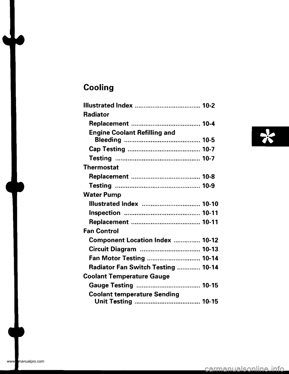
Cooling
f ffustrated Index ........... ..... 1O-2
Radiator
Rep|acement ...........,....,...................... 10-4
Engine Coolant Refilling and
Bleeding ..,.,................. 10-5
Cap Testing .................... 10-7
Testing ......10-7
Thermostat
Rep|acement ....................................... 10-8
Testing ...... 10-9
Water Pump
lllustrated lndex ....,..... .. 10-10
Inspection . 10-1 1
Replacement ....................................,.. 10-1 1
Fan Gontrol
Component Location Index ............... 10-12
Circuit Diagram ............. 10-13
Fan Motor Testing ......... 10-14
Radiator Fan Switch Testing ............. 10-14
Coolant Temperature Gauge
Gauge Testing ............... 10-15
Coolant temperature Sending
Unit Testing ........,....... 10-15
www.emanualpro.com
Page 201 of 1395

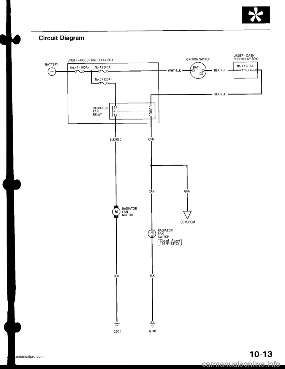
Circuit Diagram
UNDER OASHFUSEiRELAY BOX
6; E;';lwHTsLka rtF',*",El-l
I
RAOIATORFANSWITCHfClosed :Above)L 199oF {930C) J
BLK/RED
I
L^,^,.,
T*'
IBLK
I
I
oro,
IGNITION SWITCH
No.41{100A) N0.42140A)
www.emanualpro.com
Page 204 of 1395

Fuel and Emissions
Special Tools ...................... 11-2
Component Locations
lndex ...................... ....,.... 11-3
Svstem Description
Vacuum Connections ...........,....,.,................. 1 1-9
Electrical Connections ................................... 1 1-15
System Connectors .,.,,.,............................,.,. 1 1-36
Troubleshooting
Troubleshooting Procedures,.,..................... 11-60
Engine Control Module/Powertrain ConttolModule Terminal Arrangement .............., 11-67
Diagnostic Trouble Code Chart .................... 1 t-75
How to Read Flowcharts .......,.....,.,............... I 1-79
PGM-Fl System
System Description .................,.,.,,,............... 1 1-80
Troubleshooting Flowcharts
Engine Control Module/PowertrainControl Module ........11-52
Manifold Absolute Pressure Sensor ............. 11-90
Intake Air Temperature Sensor .................... 1 1-95
Engine Coolant Temperature Sensor .,..,.,.... 1 1-99
Throttle Position Sensor ...........,.....,.,.,..,...... I 1'103
Primary Heated Orygen Sensor (Sensor 1) ... 11-110
Secondary Heated Oxygen Sensor{Sensor 2l .................. 1 1-117
Heated Oxygen Sensor Heater ..................... 11-121
Fuef Supply System ......11-124
Random Misfire ,....,.,..... 11-126
Mistire Detected in One Cylinder .....-........... 11-128
Knock Sensor ................ 11-130
CKP/TDC/CYP Sensor .................................... 1 1-131
Vehicle Speed Sensor ...............................,.... 1 1-135
Barometric Pressure Sensor .....,...,...,.,,........ 1 1-137
Electrical Load Detector ...,.,.......................... 1 1-138
CKF Sensor ................,.,, '11-112
ECM/PCM lnternaf Circuit ............................. 11'117
HO2S Replacement .,.,.,. 11-148
ldle Control System
System Description ............ 11-149
Troubleshooting Flowcharts
ldle Control System ...... 11-150
fdle Air Control Valve ......................,............. 11-152
Air Conditioning Signal ................................. I 1-155
Alternator FR Signal ...................................... 1 1-159
Starter Switch Si9na1 .................................... t l-161
Power Steering Pressure Switch Signal ...... 11-162
Brake Switch Si9na1 ...................................... 11-166
Fast ldle Thermo Valve .,.,.............................,.,.,. 11-168
ldle speed setting .............. 11-169
Fuel Supply System
Fuel Lines ............................ 11-171
Fuef Tube/Ouick-Conneci Fittings ..................... 11 -175
System Description ............ 11-178
Fuel Pressurg ...................... 11-178
Fuel Iniectors ................,..... 11-179
Fuel Pressure Re9u1ator .............................,.,...., f 1-181
Fuef Fifter ....,.,.,.,,,,.,............11-142
Fuel Pump ........................... 11-183
Fuel Gauge .......................... 11-184
Fuel Gauge Sending Unit ................................... I 1-185
Low Fuel Indicator System ...........,.,..,............... 1 1-185
PGM-FI Main Relay ............. 11-187
Fue|Tank................ ............. 11-191
Intake Air System
System Description ............ 11-193
Air Cleanel ,.,.,..................... 11-194
Throttle Cable ..................... 11-194
Throttle Body........ .............. 11-196
Emission Control System
System D$cription ...,....,.,. 11-199
Tailpipe Emission ............... 11-199
Three Way Catalytic Converter ..................,.,...,, 11-199
Positive Crankcase Ventilation System .,.,,,,.,.., 11-2O1
Evaporative Emission Controls .........,.,.,............ 11-203
www.emanualpro.com
Page 266 of 1395

Troubleshooting
Troubleshooting Procedures (cont'dl
Symptom Chart
Listed below are symptoms and probable causes for problems that DO NOT cause the Malfunction Indicator Lamp (MlL) tocome on. lf the MIL was reported on, go to page 11-60.Troubleshoot each probable cause in the order listed (from left to right) until the symptom is eliminated,The probable cause and troubleshooting page reference can be found below.
Other Probable Causes for an engine that will not start:- Compression- Intake air leakage- Engine locked up- Timing belt- Starting system- Overheating- Battery
SYMPTOMPROBABLE CAUSE
Engine will not sta rt4, 2,3,5,20, 't5, 1
Hard starting2, 4, 12,17, 14, 't9
Cold fast idle too low7, a,9, 6, 17
Cold fast idle too high7,8,9,11,10
ldle speed fluctuates9,7,8, 't1, 10
Misfire or rough runningTroubleshoot for misfire on pages '11-126, 1|21LOl/\/ power2, 10,11, 13, '17, 18,20
Engine stalls2, 4, 12,1,20,9,5, 't6
Probable Cause List (For the DTC Ch8rt, see page ll-75.)
Probable CausePageSystem
Engine controt ruoaute (ecvtffi'I11-42
I 1-178Fuel oressure
PGM-Fl main relav
lgnition system
Crankshatt Position/Top Dead Center/Cylinder position sensor circuit
Intake Air Temperature (lAT) sensor ctrculr
ldle Air Control (lAC) Vatve
Fast idle thermo valve
ldle speed adjustment
Throttle body
Throftle cable
Manifold Absolute P."""rr"ffi
Throftle Position (TP) sensor
Barometric pressur" (gnno-
Ay'T gear position signal
Brake switch signal
Air Cleaner
Three Way Catalytic Converter (TWC)
Evaporative emission (EVAP) control
Contaminated fuel
1 1- 187
Section 4
5't1-'t31,146
6I '�t-95
711-152
81'l-168
1 1- 169
1011-196'1111-'194
12'1 'l -90
1 1- 103
1411-137
15Section 14
161 1- 166
17r 1-194
181 1,199'1911-203
20
11-64
www.emanualpro.com
Page 269 of 1395

Powertrain Control Module Terminal Arrangement -'97 Model
FCM CONNECTOR A (32P)NOTE: Standard battery voltage is 12 V.
Wire side of lemale terminals
f€rminalnumlreJWirecolor
Telminalnama
DescriptionSignal
YELlNJ4 (No.4 FUELINJECTOR)Drives No. 4 {uel injector.With engine running: duty controlled
2BLUlNJ3 (No.3 FUELINJECTOR)Drives No. 3luel injector.
REDlNJ2 {No.2 FUELINJECTOR)Drives No.2 tuel injector.
BRNlNJl (No. l FUELINJECTOR)Drives No. 1 fuel injector.
5BLK WHTSO2SHIC (SECONDARY
HEATED OXYGEN SENSOR HEATER CONTROL)
D ves secondary heated oxygensensor heater.With ignition switch ON {ll): battery voltageWith fully warmed up engino running: dutycontrolled
6BLKAr'YHT
PO2SHTC (PRIMARY
HEATED OXYGENSENSOR HEATERCONTROL}
Drives primary heated oxygensensor heater,With ignition switch ON lll): battery voltagewith fully warmed up engine running: dutycontroll6d
I8RN/BLKLGl (LOGIC GROUND}Ground forthe PCM control circuit.Less than 1.0 V at all times
10BLKPG1 lPOWER GROUND}Ground for the PCM power circuit.
l1YEUELKIGPl lPOWER SOURCE}Power source for the PCM controlcircuit.
With ignition switch ON (ll): battery voltageWith ignition switch OFF: 0 V
12BLI(BLUIACV {IDLE AIRCONTROL VALVE}Drives IACV.With €ngine running: duty controlled
REDryEL
PCS (EVAP PURGECONTFOL SOLENOIDVALVE)
Drives EVAP purge controlsolenoid valve.
With engine running, engine coolantbelow 154'F (68"C): battery voltageWith engine running, engine coolantabove 154"F (68"C): duty controlled
16GRN/VELFLR (FUEL PUMP RELAY)Drives Iuel pump relay.0 V for two seconds after turning ignition
switch ON lll), then battery voltage
118LI(REDACC (A,/C CLUTCHRELAY}Drives Ay'C clutch relay.With comoressor ON: 0 VWith compressor OFF: baftery voltage
18GRN/ORNMIL (MALFUNCTION
INDICATOR LAMP}Drives MlL.With MIL turned ON: 0 VWith MIL turned OFF: baftery voltage
19*WHT/GRNALTC (ALTERNATOR
CONTROL}Sends alternator control signal.With tully warmed-up engine running:
battery voltageDuring driving with smallelectrical load:0 '
20YEUGRNICM (IGNITION CONTROLMODULE)Sends ignition pulse.With ignition switch ON (ll): baftery voltageWith engine running: pulses
22BRN/BLKLG2 (LOGIC GROUND}Ground tor the PCM control circuit.Less than 1.0 V at alltimes
23BLKPG2 {POWER GROUND}Ground lor the PCM power circuit.
24YEUBLKIGP2 {POWER SOURCE}Power source for the PCM controlcircuit.
With ignition switch ON (ll): battery voltage
With engine switch OFF: 0 V
27GRNFANC (RADIATOR FANCONTROL)Drives radiator {an relay.With radiator fan running: 0 VWith radiator fan stopped: baftery voltage
*: USA
{cont'd)
11-67
www.emanualpro.com
Page 271 of 1395

PCM CONNECTOR C (31PI
ferminalnumberWirecolorTerminalnameDoscriptionSignal
'tBLUiREDCKFP (CKF SENSOR PSIDE)Detects CKF sensor.With engine running: pulses
2BLUCKPP (CKP SENSOR PSIDE)Detects CKP sensor.With engine running: pulses
3GRNTDCP (TDC SENSOR PSIDE)Detects TDC sensor.With engine running: pulses
4YELCYPP (CYP SENSOR PSIDE)Detects cYP sensor.With engine running: pulses
5BLU,frEDACS (A/C SWTTCHSIGNAL)Detects A,/C switch signal.With AJC switch ON: 0 VWith A,/C switch OFF: battery voltage
BLU/ORNSTS (STARTER SWITCHSIGNAL)
Detects starter switch signal.With starter switch ON (lll): bafteryvoltageWith staner switch OFF: 0 V
7BRNSCS (SERVICE CHECKSIGNAL)
Detects service check connectorsignal (the signal causing a DTCindication)
With the connector connected: 0 V
With the connector disconnected: about
5 V or battery voltage
8LT BLUK-LINESends and receives scan toolsrgnal.With ignition switch ON (ll): pulses
10WHT/BLUVBUUP)
(VOLTAGE BACKPower source tor the PCMcontrol circuit. Power source for
the DTC memory
Battery voltage at all times
11WHT/REDCKFM (CKF SENSOR MSIDE)Ground for CKF sensor signal.
12WHTCKPM (CKP SENSOR I\4SIDE)Ground lor CKP sensor signal.
13REDTDCM (TDC SENSOR MSIDE}Ground for TDC sensor signal.
14BLKCYPM (CKP SENSOR MSIDE}Ground for CYP sensor signal.
16GRN
PSPSW (P/S PRESSUREswtTcH)Detects PSP switch signal.At idle with steering wheel in straightahead position:0 VAt idle with steering wheel at full lock:
battery voltage
17WHT/REDALTF (ALTERNATOR FRSIGNAL)
Detects alternator FR signal.With fully warmed up engine running:
0 V-battery voltage {depending onelectrical load)
18BLUA/VHTVSS (VEHICLE SPEEDSENSOR)Detects VSS signal.Wirh ignition switch ON (ll) and frontwheels rotating: cycles 0 V - 5 V or bat-tery voltage
Wire side of femaie terminalsPCM CONNECTOR C {31PINOTE: Standard battery voltage is 12 V.
(cont'd)
www.emanualpro.com
Page 274 of 1395

Troubleshooting
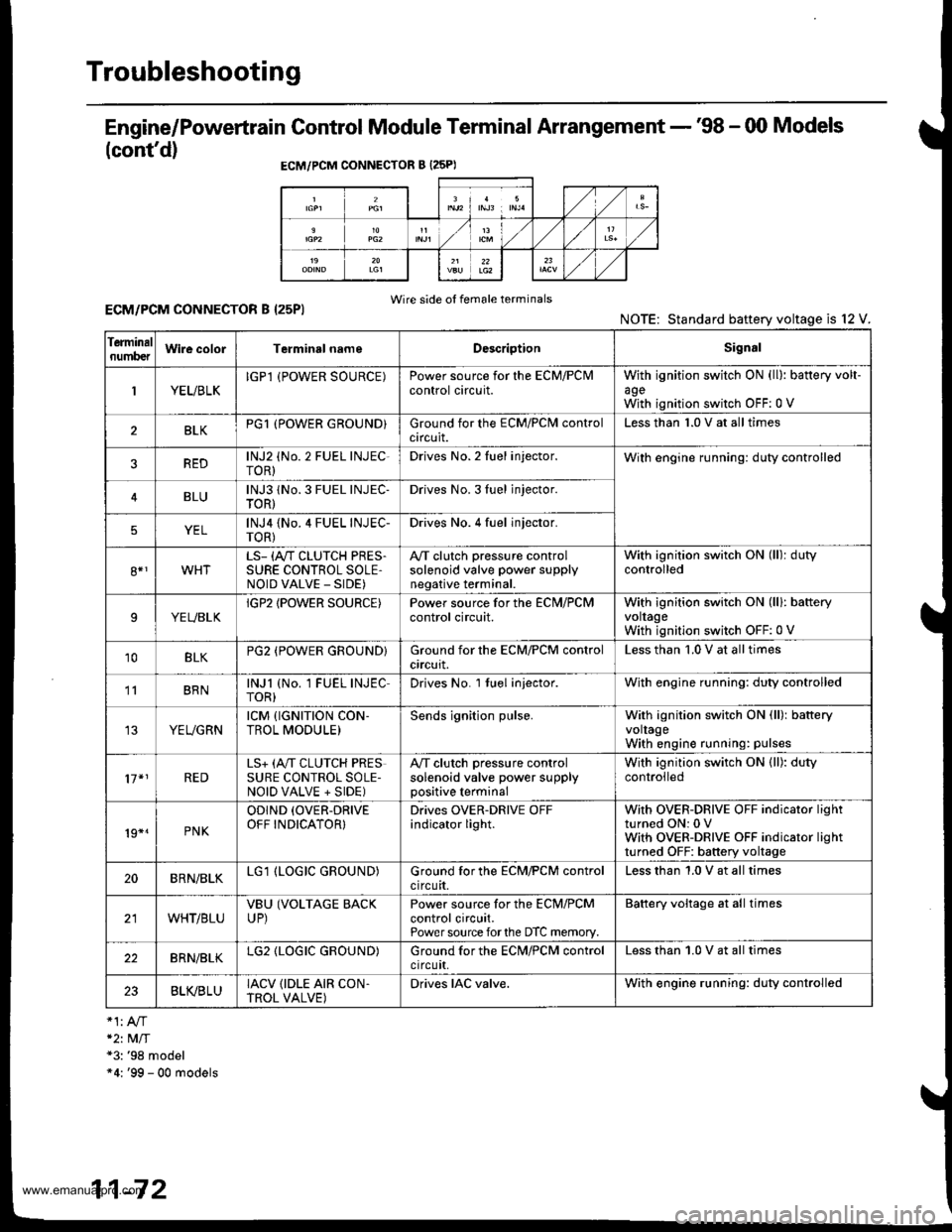
Engine/Powertrain Control Module Terminal Arrangement - '98 - 00 Models
(cont'd)
ECM/PCM CONNECTOR B {25PI
Wire side of female terminalsECM/PCM CONNECTOR B I25PI
*2t MlT*3: '98 model"4: '99 - 00 models
NOTE: Standard baftery voltage is l2
Ierminalnumb€tWire colorTerminsl nameDescriptionSignal
1YEUBLKIGPl (POWER SOURCE)Power source for the ECM/PClvlcontrol circuit.withagewith
ignition switch ON (ll): battery volt-
ignition switch OFF:0 V
BLKPG1 (POWER GROUND}Ground for the ECM/PClvl controlcircuit.Less than 1.0 V at all times
REDlNJ2 (No. 2 FUEL INJEC-roR)Drives No. 2 Iuel injector.With engine running: duty controlled
BLUlNJ3 1No. 3 FUEL INJEC-TOR)Drives No. 3Iuel jnjector.
YELlNJ4 {No.4 FUEL INJEC-TOR)Drives No. 4 fuel injector.
8*1WHTLS- (A"/T CLUTCH PRES.SURE CONTROL SOLE,NOID VALVE _ SIDE)
A,/T clutch pressure controlsolenoid valve power supplynegative terminal.
With ignition switch ON (ll): dutycontrolled
9YEUBLKIGP2 IPOWER SOURCE)Power source for the ECN,I/PCMcontrol circuit.With ignition switch ON (lll: bafteryvoltageWith ignition switch OFF:0 V
10BLKPG2 (POWER GROUND}Ground for the ECM/PCM controlcrrcurt.Less than '1.0 V at all times
' BRNlNJl (No. 1 FUEL INJECTOR)Drives No. l tuel injector.With engine running: duty controlled
YEUGRNrcM {rGNrTroN coN-TROL MODULE)Sends ignition pulse.With ignition switch ON (ll): batteryvoltageWith engine running: pulses
17*1REDLS+ (A,,IT CLUTCH PRESSURE CONTROL SOLE-NOID VALVE + SIDE)
A,/T clutch pressure controlsolenoid valve power supplypositive terminal
With ignition switch ON (ll): dutycontrolled
19*.PNK
ODIND (OVER-DRIVE
OFF INDICATOR}Drives OVER-DRIVE OFFindicator light.With OVER-DRIVE OFF indicator lightturned ON: 0 VWith OVER-DRIVE OFF indicator lightturned OFF: battery voltage
20BRN/BLKLG1 (LOGIC GROUND)Ground for the ECM/PCM controlcircuit.Less than 1.0 V at all times
WHT/BLUVBU (VOLTAGE BACKUP)Power source for the ECM/PCMcontrol circuit.Power source forthe DTC memory.
Battery voltage at all times
22BRN/BLKLG2 (LOGIC GROUND)Ground for the ECN4/PCM controlctrcutt,Less than 1.0 V at all times
23BLVBLUIACV {IDLE AIR CON.TROL VALVE)Drives IAC valve.With engine running: duty controlled
11-72
www.emanualpro.com