2000 HONDA CR-V housing
[x] Cancel search: housingPage 885 of 1395
Power Steering Gearbox
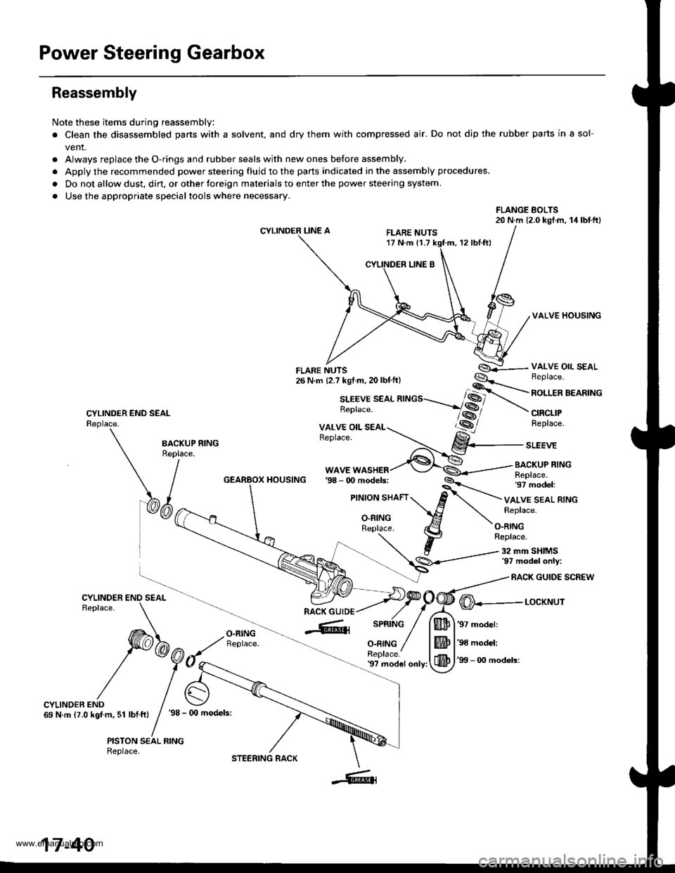
Reassembly
Note these items during reassembly
. Clean the disassembled parts with a solvent, and dry them with compressed air. Do not dip the rubber parts in a sol-
vent.
. Always replace the O-rings and rubber seals with new ones before assembly.
. Apply the recommended power steering fluid to the parts indicated in the assembly procedures.
. Do not allow dust. dirt, or other toreign materials to enter the power steering system.
. Use the appropriate specialtools where necessary.
FLANGE BOLTS20 N.m (2.0 kgl.m, 14lbtftl
CYLINDER LINE AFLARE NUTS17 N.m 11.712 rbl.ftl
VALVE HOUSING
CYLINDER END SEALReplace.
VALVE OIL SEALBeplace.
ROLLER BEARING
CIRCLIPReplace.
BA.KUP RING
\/^"
WAVE WASHERBACKUP RINGReplace.97 model:HOUSING
VALVE SEAL RINGReplace.
O.RINGReplace.
32 mm SHIMS'97 mod6l only:
RACK GUIDE SCREW
O-RINGReplace.
@---r-ocxr'rur
'97 model:
'98 model:
'99 - 0O mod6ls:'9? model only:
CYLINDER END69 N.m (7.0 kgf.m, 51 lbf.ft)'98 - (x) models:
PISTON SEAL RINGReplace.
17-40
STEERING RACK
www.emanualpro.com
Page 888 of 1395
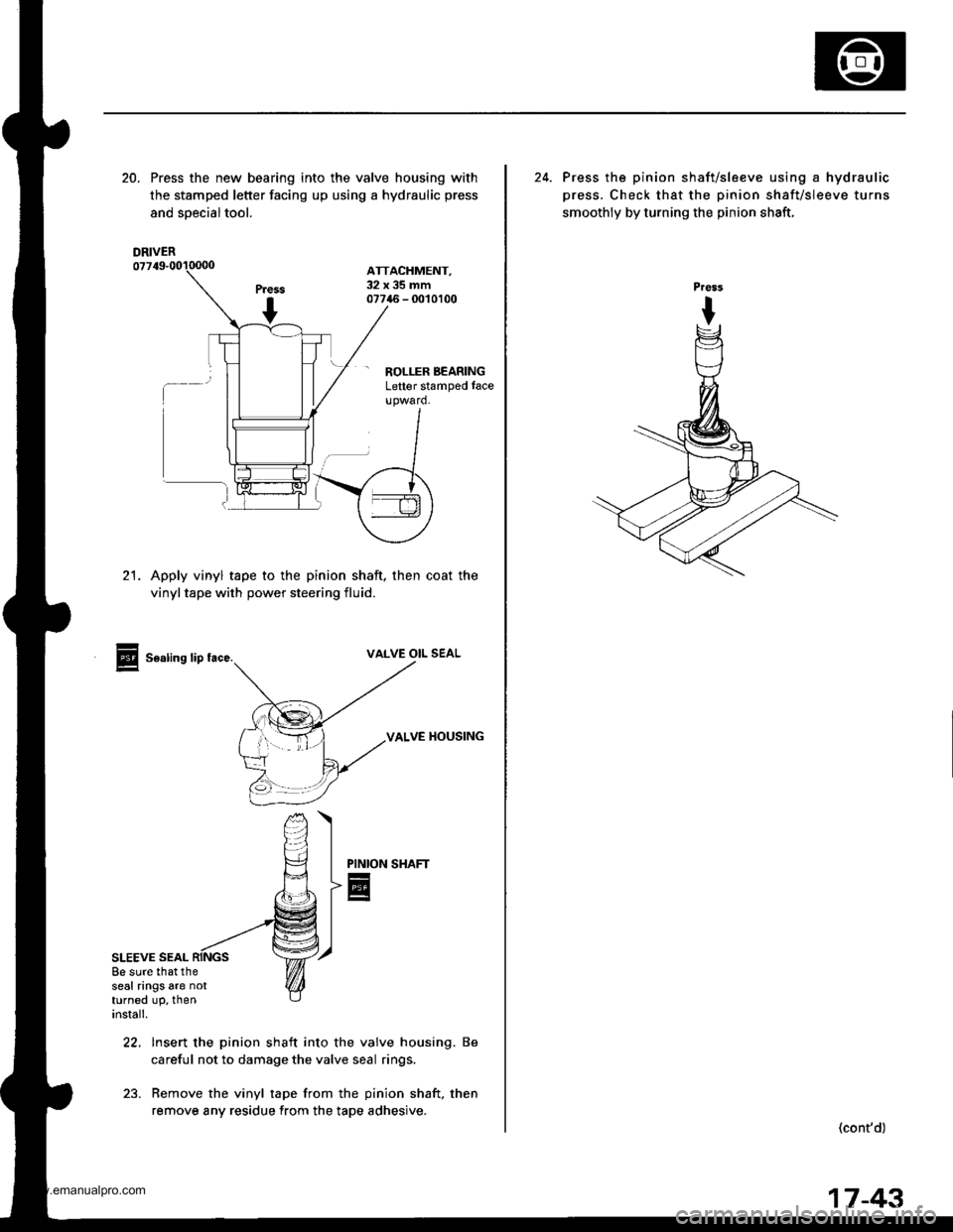
20. Press the new bearing into the valve housing with
the stamped letter facing up using a hydraulic press
and soecialtool.
ATTACHMENT,32x35mm07746 - 0010100
- ROLLER BEARINGLetter stamped face
21. Apply vinyl tape to the pinion shaft, then coat the
vinyltape with power steering fluid.
Sealing lip tace.VALVE OIL SEAL
VALVE HOUSING
SHAFT
SLEEVE SEAL
PINION
E
22, Insert the pinion shaft into the valve housing. Be
careful not to damage the valve seal rings.
23. Remove the vinyl tape from the pinion shaft, then
remove any residue from the tape adhesive.
8e sure that theseal rings are notturned up, theninstall.
DRIVER
24. Press the pinion shaft/sleeve using a hydraulic
press. Check that the pinion shaft/sleeve turns
smoothly by turning the pinion shaft,
(cont'd)
17-43
www.emanualpro.com
Page 890 of 1395
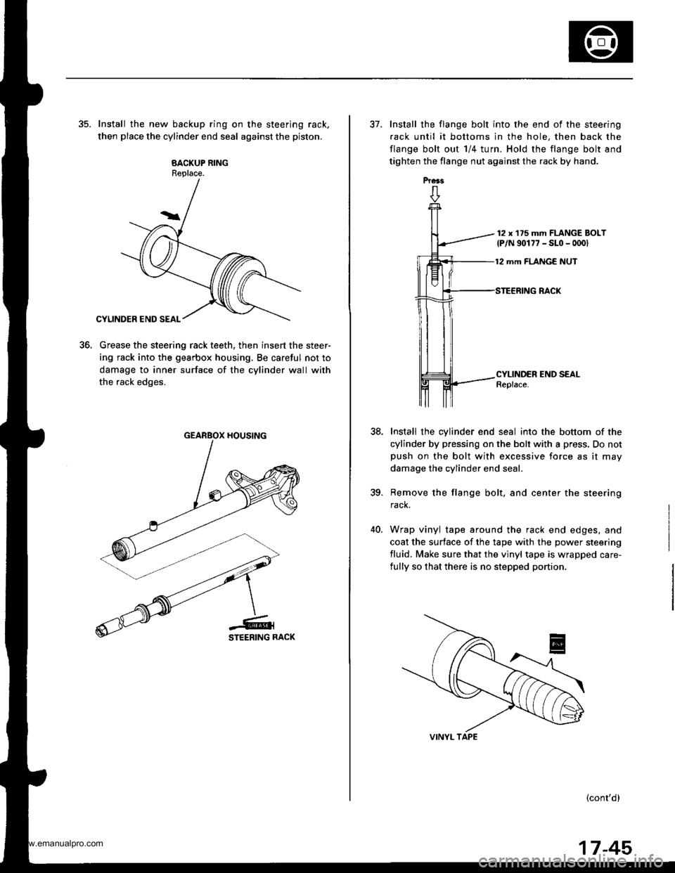
35. Install the new backup ring on the steering rack,
then place the cylinder end seal against the piston.
BACKUP RINGReplace.
Grease the steering rack teeth, then insert the steer-
ing rack into the gearbox housing, Be careful not to
damage to inner surface of the cylinder wall with
the rack edges.
to.
GEARBOX HOUSING
Prers
37. Install the flange bolt into the end of the steering
fack until it bottoms in the hole, then back the
flange bolt out 1/4 turn. Hold the flange bolt and
tighten the flange nut against the rack by hand.
12 x'175 mm FLANGE BOLT
lP/N 90177 - SLo - 0001
12 mm FLANGE NUT
38.
CYLINDER END SEALReplace.
Install the cylinder end seal into the bottom of the
cylinder by pressing on the bolt with a press, Do notpush on the bolt with excessive force as it may
damage the cylinder end seal.
Remove the flange bolt, and center the steering
rack.
Wrap vinyl tape around the rack end edges, and
coat the surface of the tape with the power steering
fluid. Make sure that the vinyl tape is wrapped care-
fully so that there is no stepped portion.
(cont'dl
ia
40.
17-45
www.emanualpro.com
Page 891 of 1395
Power Steering Gearbox
Reassembly (cont'dl
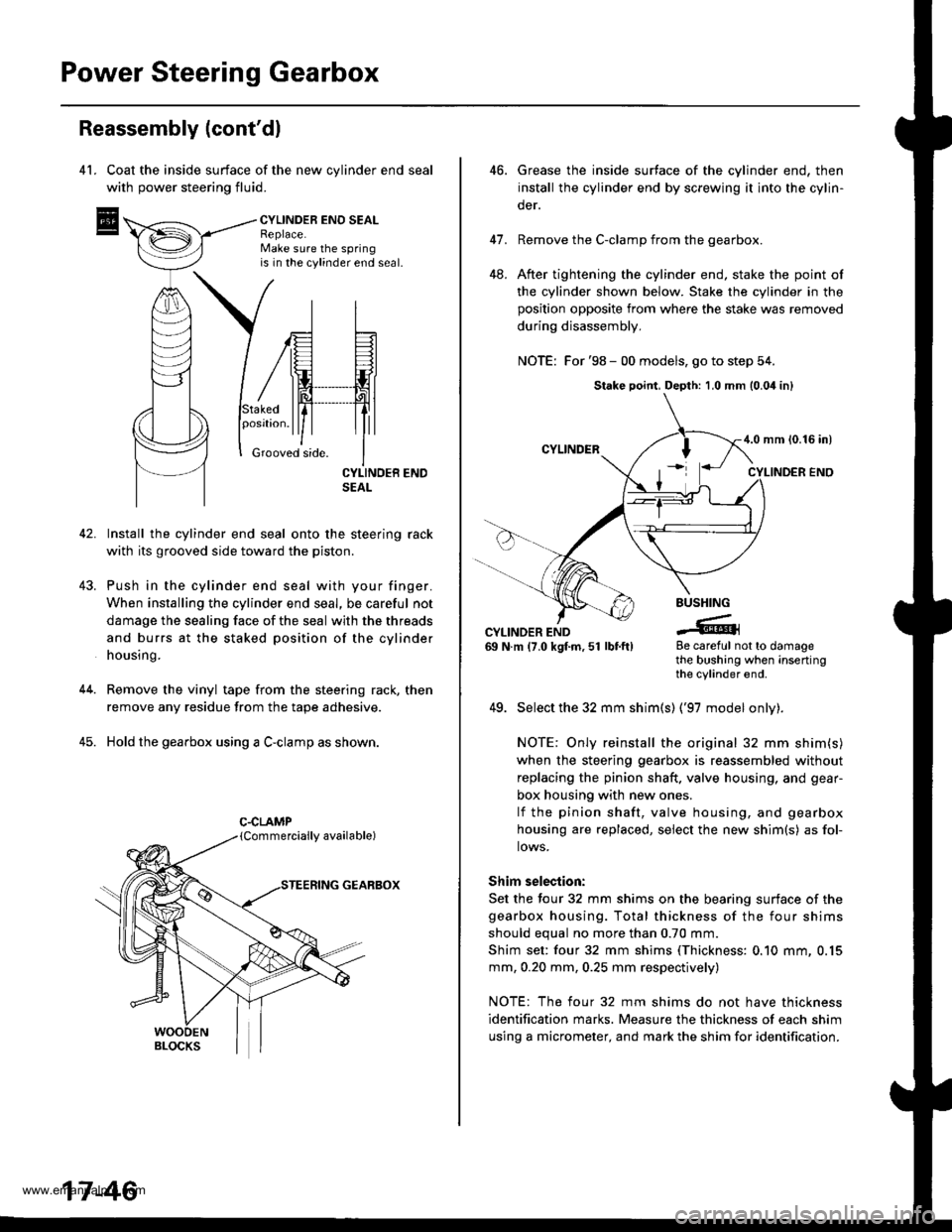
4l. Coat the inside surface of the new cvlinder end seal
with power steering fluid.
CYLINDEB ENO SEALReplace.Make sure the springis in the cylinder end seal.
43.
Stakedposrtron.
Grooved side.
42. Install the cylinder end seal onto the steering rack
with its grooved side toward the piston.
Push in the cylinder end seal with your finger.
When installing the cylinder end seal, be careful not
damage the sealing face of the seal with the threads
and burrs at the staked position of the cylinder
housing.
Remove the vinyl tape from the steering rack, then
remove any residue from the tape adhesive.
Hold the gearbox using a C-clamp as shown.
GEARBOX
44.
45.
C.CLAMP
17-46
46.Grease the inside surtace of the cylinder end, then
install the cylinder end by screwing it into the cylin-
der.
Remove the C-clamp from the gearbox.
After tightening the cylinder end, stake the point of
the cylinder shown below. Stake the cylinder in the
position opposite from where the stake was removed
during disassembly,
NOTE: For '98 - 00 models, go to step 54.
41.
48.
BUSHING
-tGCYLINDER END69 N.m (7.0 kgf.m,51 lbtft)8e careful not to damagethe bushing when insertingthe cylinder end.
49. Select the 32 mm shim(s) ('97 model onlv).
NOTE: Only reinstall the original 32 mm shim(s)
when the steering gearbox is reassembled without
replacing the pinion shaft. valve housing, and gear-
box housing with new ones.
lf the pinion shaft, valve housing, and gearbox
housing are replaced, select the new shim{s) as fol-
lows.
Shim selection:
Set the four 32 mm shims on the bearing surface of the
gearbox housing. Total thickness of the four shims
should equal no more than 0.70 mm.
Shim set: four 32 mm shims (Thickness: 0.10 mm, 0.15
mm, 0.20 mm, 0.25 mm respectively)
NOTE: The four 32 mm shims do not have thickness
identification marks. Measure the thickness of each shim
using a micrometer, and mark the shim for identification.
Stake point, Depth: 1,0 mm (0.04 inl
4.0 mm {0.16 in)
www.emanualpro.com
Page 892 of 1395
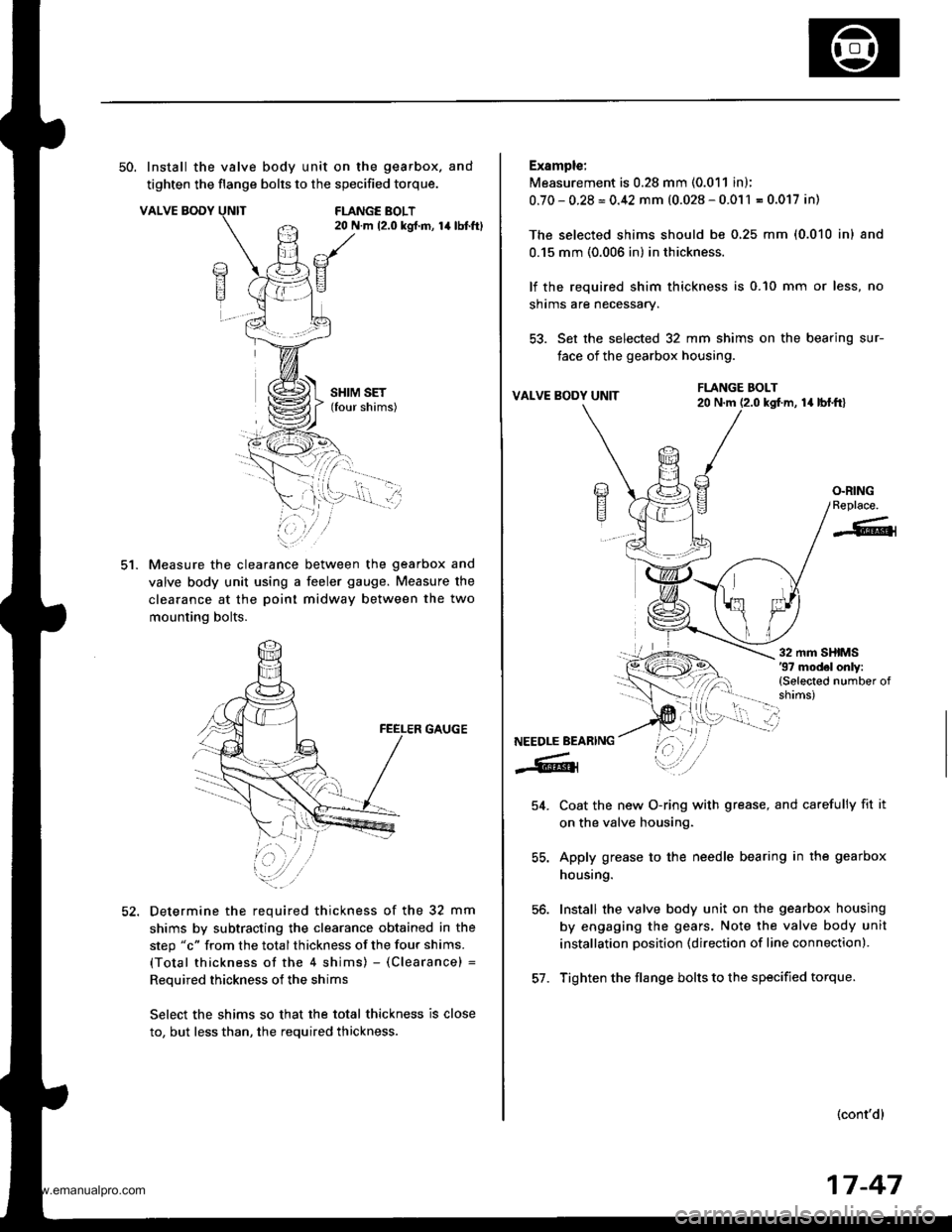
50. Install the valve body unit on the gearbox. and
tighten the flange bolts to the specified torque.
VALVE BODYFLANGE BOLT20 N.m 12.0 kgt.m, 14lbtft)
ct.
SHIM SET(four shims)
Measure the clearance between the gearbox and
valve body unit using a feeler gauge. Measure the
clearance at the poinl midway between the two
mounting bolts.
GAUGE
Determine the required thickness of the 32 mm
shims by subtracting the clearance obtained in the
step "c" from the total thickness of the four shims.
(Total thickness of the 4 shims) - (Clearance) =
Reouired thickness of the shims
Select the shims so that the total thickness is close
to, but less than, the required thickness.
Example:
Measurement is 0.28 mm (0.011 in);
0.70-0.28=0.42 mm (0.028-0.011 = 0.017 in)
The selected shims should be 0,25 mm (0.010 inl and
0.15 mm (0.006 in) in thickness.
lf the required shim thickness is 0.10 mm or less, no
shrms are necessary.
53. Set the selected 32 mm shims on the bearing sur-
face of the gearbox housing.
VALVE BODY UNITla lbl.frl
Coat the new O-ring with grease, and carefully fit it
on the valve housing.
Apply grease to the needle bearing in the gearbox
housing.
Install the valve body unit on the gearbox housing
by engaging the gears. Note the valve body unit
installation position (direction of line connection).
Tighten the flange bolts to the specified torque.
(cont'd)
FLANGE BOLT20 N.m (2.0 kgf.m,
/a)E?
E
O.RINGReplace.
-6{
NEEDLE BEARING
-6lr
54.
56.
57.
17-47
www.emanualpro.com
Page 893 of 1395
Power Steering Gearbox
Reassembly (cont'dl
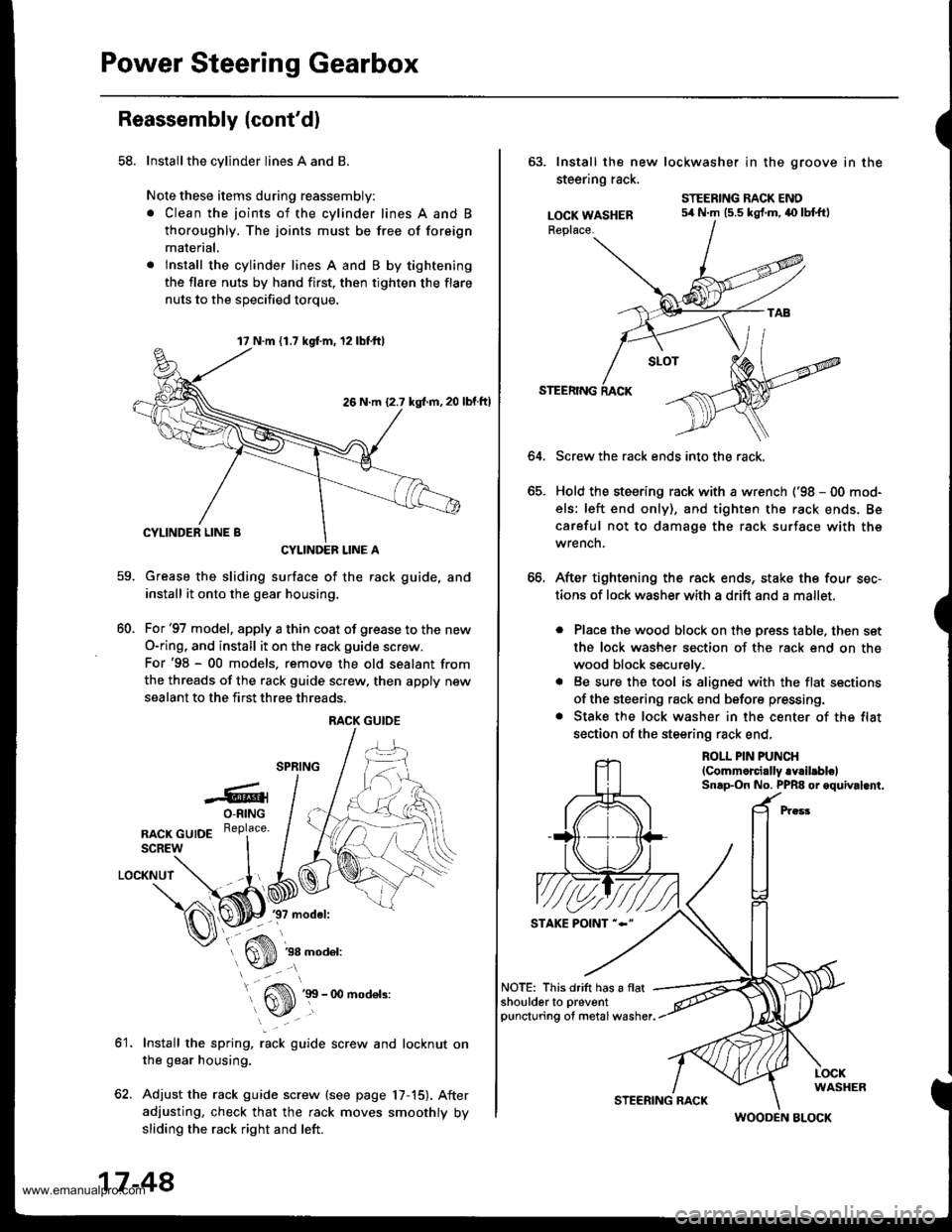
58. Installthe cylinder lines A and B
Note these items during reassembly:
. Clean the joints of the cylinder lines A and B
thoroughly. The joints must be free of foreign
material,
. lnstall the cylinder lines A and B by tightening
the flare nuts by hand first, then tighten the flare
nuts to the soecified torque.
CYLINDEF LINE A
Grease the sliding surface of the rack guide, and
install it onto the gear housing.
For'97 model, apply a thin coat of grease to the new
O-ring, and install it on the rack guide screw.
For'98 - 00 models. remove the old sealant from
the threads of the rack guide screw. then apply new
sealant to the first three threads.
-6rO-RING
nlcr cutDE R"Pl""u'
SCREW
LOCKNUT
37 model:
60.
ot.
38 model:
Install the spring, rack guide screw and locknut on
the gear housing.
Adjust the rack guide screw (see page 17,15). After
adjusting, check that the rack moves smoothly by
sliding the rack right and left.
17 N.m 11.7 kgd.m, 12lbf.ttl
26 N.m {2.7 kgl.m, 20
RACK GUIOE
17-48
STEERING RACK
(
63. Install the new lockwasher in the groove in the
steering rack.
LOCK WASHERReplace.
STEERING RACK ENO54 N.m (5.5 kgf.m,40 lbtftl
64.
STEERING
Screw the rack ends into the rack.
Hold the steering rack with a wrench ('98 - 00 mod-
els: left end only), and tighten the rack ends. Be
careful not to damage the rack surface with the
wrench.
After tightening the rack ends, stake the four sec-
tions of lock washerwith a drift and a mallet.
. Place the wood block on the press table, then set
the lock washer section of the rack end on the
wood block securely.
. Be sure the tool is aligned with the flat sections
of the steering rack end before pressing.
. Stake the lock washer in the center of the flat
section of the steering rack end,
ROLL PIN PUNCH
lCommorcially.Y.il.blelSnap-On No. PPR8 or oquival.nt.
NOTE: This drift has a flatshoulderto preventpuncturing of metal washer.
WOODEN BLOCK
www.emanualpro.com
Page 894 of 1395
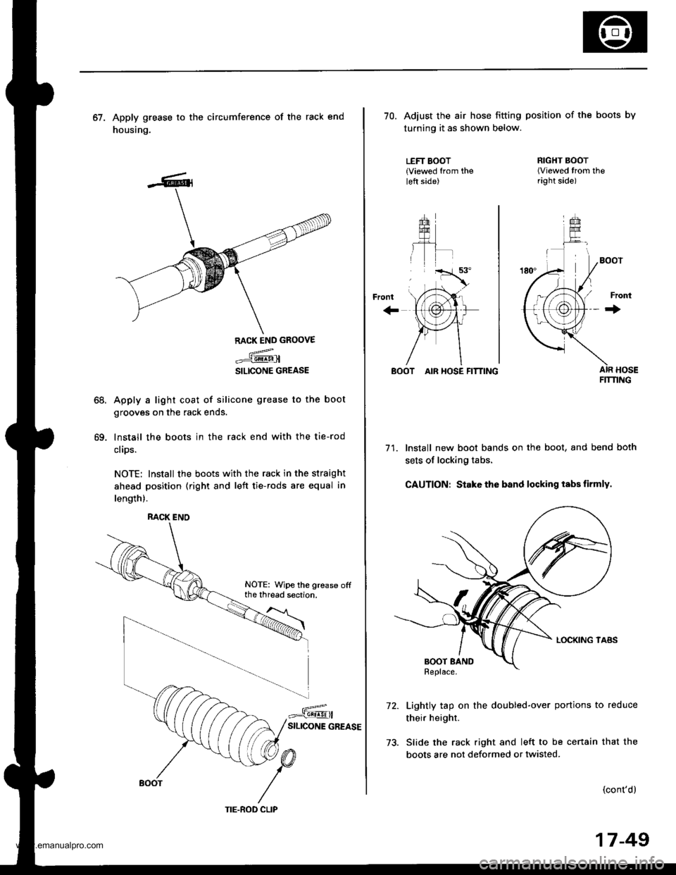
67. Apply grease to the circumference of the rack end
housing.
68.
69.
RACK END GROOVE
.={@
SILICONE GREASE
Apply a light coat of silicone grease to the boot
grooves on the rack ends.
lnstall the boots in the rack end with the tie-rod
clips.
NOTE: Install the boots with the rack in the straight
ahead position (right and left tie-rods are equal in
length).
RACK ENO
NOTE: Wipe the grease offthe thread section.
TIE.ROD CLIP
17-49
70. Adiust the air hose fitting position of the boots by
turning it as shown below.
LEFT BOOT{Viewed from theleft side)
+rom
''rT.a'.
, tri"
\,'tAr-
{,1@}tr
)Fr1
/\
RIGHT BOOT(Viewed trom theright side)
Front
+
BOOT AIR HOSE FITTING
71. Install new boot bands on the boot, and bend both
sets of locking tabs.
CAUTION: Stake the band locking tabs firmly.
Lightly tap on the doubled-over portions to reduce
their height.
Slide the rack right and left to be cenain that the
boots are not deformed or twisted.
(cont'd)
FIT'I'ING
www.emanualpro.com
Page 913 of 1395
'1.
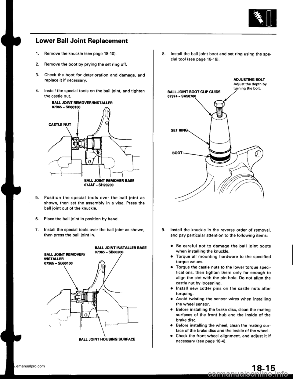
Lower Ball Joint Replacement
Remove the knuckle (see page 18-10).
Remove the boot by prying the set ring off.
Check the boot for deterioration and damage. and
replace it if necessary.
lnstall the special tools on the ball joint, and tighten
the castle nut.
BAII JOINT BEMOVER BASE07JAF - SH2oe00
Position the special tools over the ball joint as
shown. then set the assembly in a vise. Press the
ball joint out of the knuckle.
Place the ball joint in position by hand.
Install the special tools over the ball joint as shown,
then press the balljoint in.
BAII JOINT INSTAL1IR BASE
7.
8AI.I JOINT REMOVEN/INSTALLER
BALL JOINT HOUSING SURFACE
18-15
8. Install the ball joint boot and set ring using the spe-
cial tool {see page 18-16}.
Install the knuckle in the reverse order of removal.
and pay particular attention to the following items:
. Be careful not to damage the ball joint boots
when installing the knuckle.
. Torque all mounting hardware to the specified
toroue values.
a Torque the castle nuts to the lower torque speci-
fications, then tighten them only far enough to
align the slot with the pin hole. Do not align the
castle nut by loosening.
. Install new cotter pins on the castle nuts after
IOrqurng.
Avoid twisting the sensor wires when installing
the wheel sensor.
Before installing the brake disc, clean the mating
surfaces of the front hub and the inside of the
brake disc.
Before installing the wheel. clean the mating sur-
face of the brake disc and the inside of the wheel.
Check the front wheel alignment, and adjust it if
necessary (see page 18-4).
o
www.emanualpro.com