Page 1143 of 1395
Temperature Control
Adjustment
l. From under the hood, open the cable clamp, then
disconnect the heater valve cable from the heater
vatve arm.
From under the dash, disconnect the heater valve
cable housing from the cable clamp. and disconnect
the heater valve cable from the air mix contlol arm
Set the temperature control dial on MAX COOL with
the ignition switch ON (ll).
Attach the heater valve cable to the air mix control
arm as shown above. Hold the end of the heater
valve cable housing against the stop, then snap the
heater valve cable housing into the cable clamp.
HEATER VALVE ARM
HEATER VALVE CABLE
5. From under the hood. turn the heater valve arm to
the fullv closed position as shown, and hold it.
Attach the heater valve cable to the heater valve
arm, and gently pull on the heater valve cable hous-
ing to take up any slack, then install the heate. valve
cable housing into the cable clamp.
HEATER VALVE ARM
HEATER VALVE CABLE
22-53
www.emanualpro.com
Page 1169 of 1395
DAYTIME BUNNING LIGHTSCONTROL UNIT (Canrda) {'98 - (X) modok)IGNITION KEY LIGHTCONTROL UNIT l€7 model)
OAYTIME RUNNING LIGHTSCONTROL UNIT lcanad!l l'97 modell
CRUISE CONTNOL UNIT
HORN BELAY 137 modellIwiro color3: WHT/GRN, IIWHT/GBN, GRY, and BLU/REDI
IWir6 color3: BLK/WHT, BLK^ UHT,I
lGRY,.nd BLx/nED I
STARTER CUT RELAY {'98 - 00 modelsl
STARTEn CUT RELAY l€7 mod€ll
lwire colors: BLK/WHT, BLK/WHY,l
IGRY, and BLK/RED IHORN FELAY l'98 - 00 modcb)lwire coloF: WHT/GRN, lLWHT/GRN, GRY, and BLU/REDI
{cont'd)
23-9
www.emanualpro.com
Page 1204 of 1395

Power Distribution
Fuse
1
3
5
6
7
I
9
10
11
12
13
14
"^
RED/B LU
RED/GRN
WHT/BLK
RED/VVHT
YEUBLK
RED
GRN/BLK
BLU/BLK
YEVBLK
YEUGRN
RED
BLK/YE L
BLK/VVHT
17
7.5 A
7.5 A
BLVBLU
BLKA/EL
18
19
20
22
7.54
7.54
l0 A
10 A
YEUBLK
YEVRED
BLKAr'YHT
RED /VHT
RED/YE L
Fuse-to-Component(sl Index (numerical sequencel (cont'dl
Under-dash Fuse/Relay Box:
Capacity
10 A
10 A
10 A
10 A
20A
204
15A
204
204
7.5 A'15 A
7.5 A
7.5 A
Wire ColorCircuit{s) Protected
Not used
Not used
Rear window washer motor (via switch)
Rear window wiper control unit ('97 model)
Rear window wiper motor
Daytime running rights resister {Canada)
Right headlight {High beam}
Daytime running rights resister (Canada)
High beam indjcator light
Left headlight (High beam)
Rear accessory socket (via relay)
Left rear power window motor (via switch)
Right rear power window motor (via switch)
Distributor (ignition control module)
Front passenger's power window motor (via switch)
Driver's power window motor {via switch)
Power window master switch (power window control unit)
Turn signal/hazard relay (via switch)
PGM-FI main relay
SRS unit (VA)
Cruise control unit (via switch)
Cruise main switch indicator light
Alternator
Charging system light
ELD unit (USA)
EVAP bypass solenoid valve ('98 - 00 models)
EVAP control canister vent shut valve ('98 - 00 models)
EVAP purge control solenoid valve
Primary HO2S
Secondary H02S
VSS
ABS control unit
Option connector (lG2)
Ay'C compressor clutch relay
Blower motor high relay
Blower motor relay
Condenser fan relay
Heater control panel
Left power mirror actuators (via switch)
Mode control motor
Radiator fan relay
Recirculation control motor
Right power mirror actuators (via switch)
Daytime running lights control unit (Canada)
Back-up lights
Reverse relay (A"/T)
Daytime running lights control unit (Canada)
Right headlight (Low beam)
Left headlight (Low beam)
23-44
www.emanualpro.com
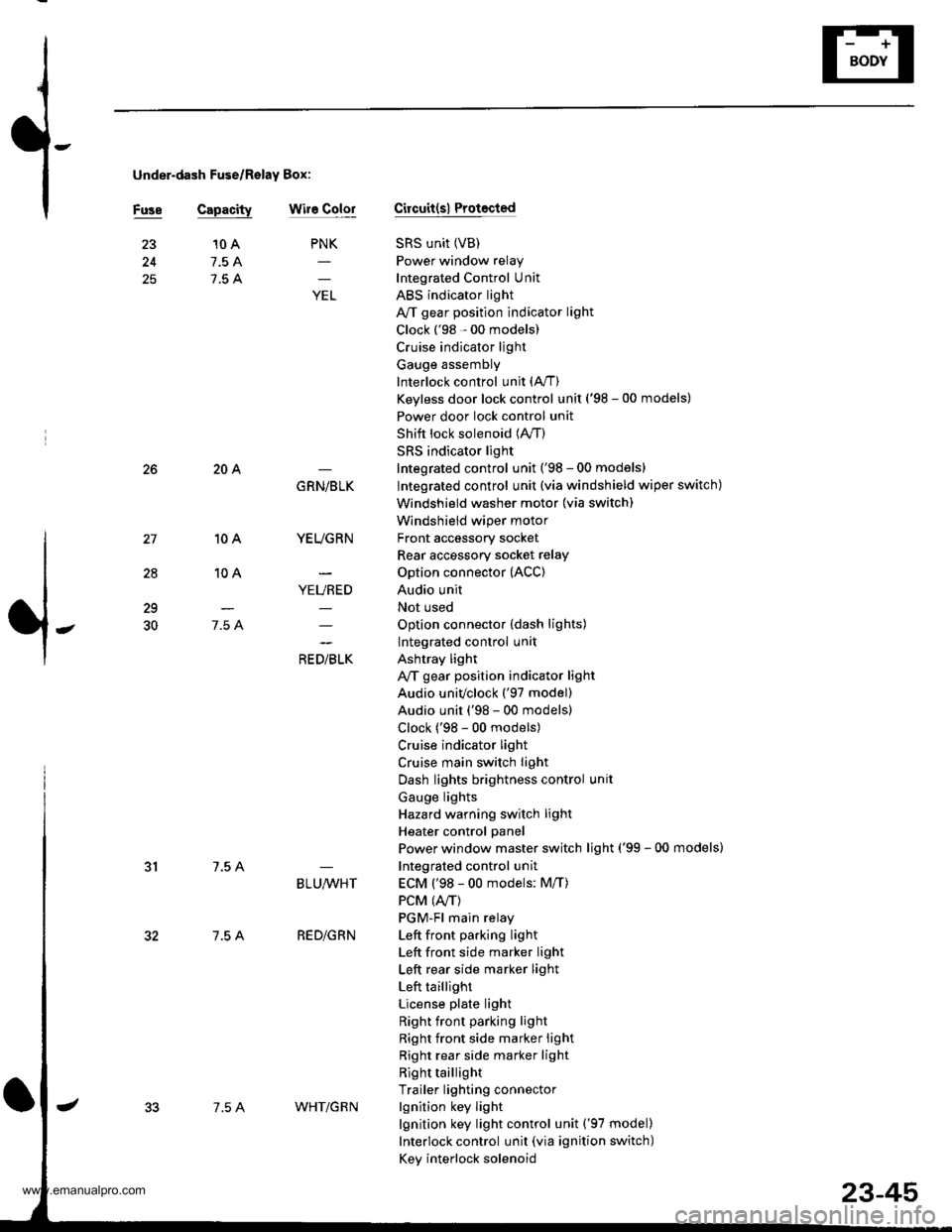
Page 1205 of 1395

under-dash Fuse/Relay Box:
Fuse Capacitywir6 ColorCircuit(sl Protocted
SRS unit (VB)
Power window relay
Integrated Control Unit
ABS indicator light
A/T gear position indicator light
Clock ('98 - 00 models)
Cruise indicator light
Gauge assembly
Interlock control unit (A,/T)
Keyless door lock control unit ('98 - 00 models)
Power door lock control unit
Shift lock solenoid (lVT)
SRS indicator light
Integrated control unit ('98 - 00 models)
Integrated control unit (via windshield wiper switch)
Windshield washer motor (via switch)
Windshield wiper motor
Front accessory socket
Rear accessory socket relay
Option connector (ACC)
Audio unit
Not used
Option connector (dash lights)
Integrated control unit
Ashtray light
A,/T gear position indicator light
Audio univclock ('97 model)
Audio unit ('98 - 00 models)
Clock ('98 - 00 models)
Cruise indicator light
Cruise main switch light
Dash lights brightness control unit
Gauge lights
Hazard warning switch light
Heater control panel
Power window master switch light ('99 - 00 models)
Integrated control unit
ECM ('98 - 00 models: M/T)
PCM (4./T)
PGM-Fl main relay
Left front pa.king light
Left front side marker light
Left rear side marker light
Left taillight
License plate light
Right front parking light
Right front side marker light
Right rear side marker light
Right taillight
Trailer lighting connector
lgnition key light
lgnition key light control unit ('97 model)
Interlock control unit (via ignition switch)
Key interlock solenoid
25
PNK
;
10 A
7.5 A
7.5 A
28
10A
10A
7.5 A
204
7.5 A
7.5 A
GRN/BLK
YEUGRN
YEURED
a, olrL"
29
30
BLU,ryVHT
RED/GRN
7.5 AWHT/G R N
23-45
www.emanualpro.com
Page 1216 of 1395
Gauge Assembly
Gau ge/lndicator/Terminal Location Index
CONNECTOR "A"
{A/T GEAB POSITION INDICATOR)
CONNECTOR "D-
{ABS INDICATOR)CONNECTOR "E"
{CBUISE INDICATOR'CONNECTOR "F"
{SRS INDICATOR}
SPEEDOMETER:Indicates 60 km/h at 637 rpm or60 mph at 1,026 rpm ofthevehicle speed sensor (VSS).
TACHOMETER:lndicates 100 rpm at200 pulses per minuteof the ignition controlmodule (lCM).
23-56
a1___-__-____>816
JilililIJililil1
cl --------->cl3
JililtHililL
,
.. "€""^
o o ue ou
t)1- --->t)5E1- - -->E5Fl---->F5
oo/ \oo
www.emanualpro.com
Page 1219 of 1395
t -, IrJr--------11-.----..1'\-J
IITBLK/YEL I BLUMHT
BLKMHTJ 'i- | g
ltY
(}-.
YEL _
TURN SIGNAUHAZARD WARNINGswrTcH
YYY
IGNITIONCONTROLI/lODULEIcM)
f7
IBLU
1.,
No.s i10A) .--......_FUSE LEFT RIGHT
MALFUNCTIONINDICATORtA[rP ([,{tL){1.4W1
l.,CRN/ORN
I
PCM
COOLANTTEII,4PERATURESENDINGUNIT
BLK
T
G552
(cont'd)
23-59
G401G402
www.emanualpro.com
Page 1230 of 1395

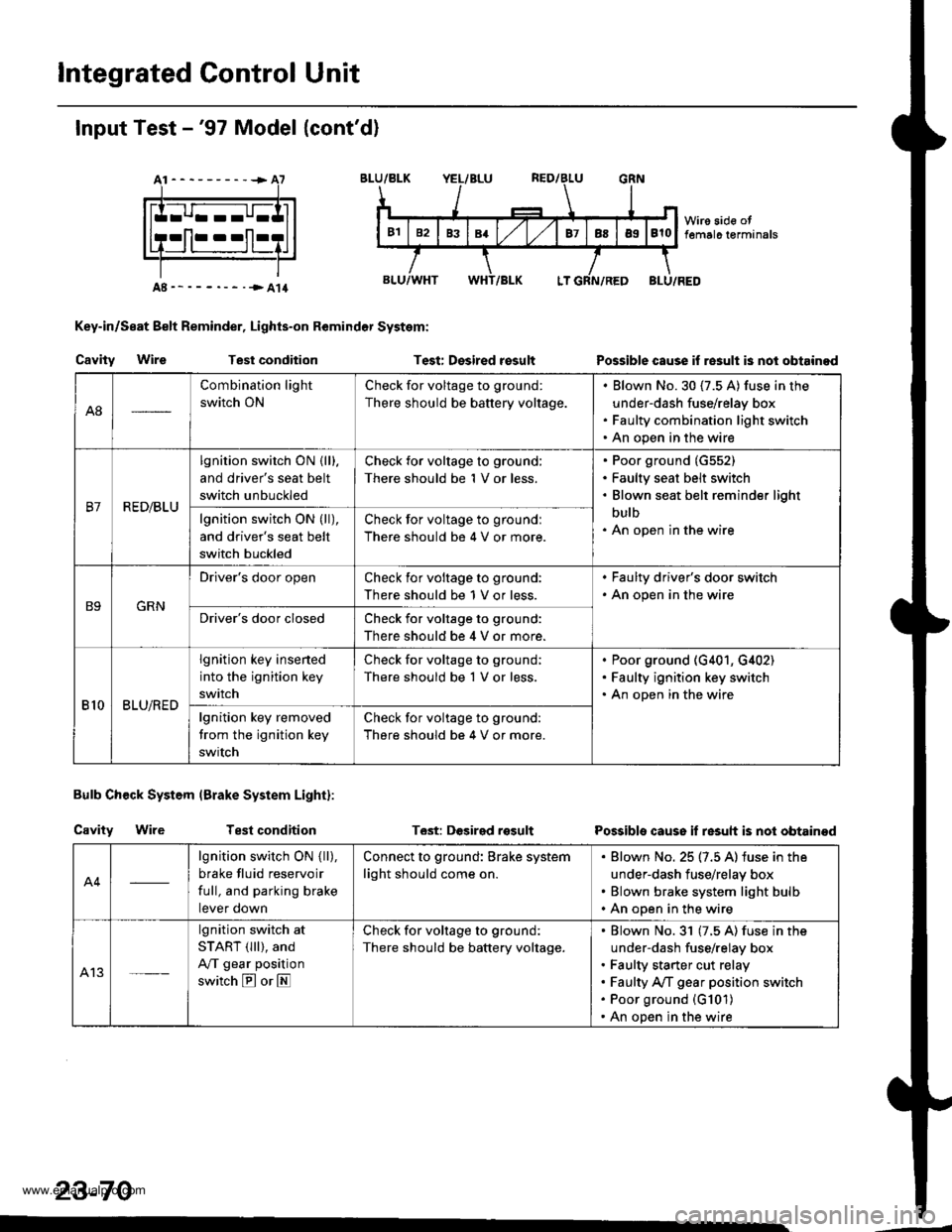
lntegrated Control Unit
Input Test -'97 Model (cont'd)
At----------+A7
Key-in/Seat Belt Reminder, Lights-on Remindor System:
Cavity WireTest conditionTest: Desired rosultPossible cause if re3ult is nol obtainod
Bulb Check System (Brake System Light):
Cavity WireTest conditionT6st: DGsirgd rosultPossible cause if resuh is not obtainod
23-70
A8
Combination light
switch ON
Check for voltage to ground:
There should be battery voltage.
Blown No.30 (7.5 A) fuse in the
under-dash fuse/relay box
Faulty combination light switch
An open in the wire
B7R ED/BLU
lgnition switch ON {lll.
and driver's seat belt
switch unbuckled
Check for voltage to ground:
There should be 1 V or less.
Poor ground (G552)
Faulty seat belt switch
Blown seat belt reminder light
bulb
An open in the wirelgnition switch ON (ll),
and driver's seat belt
switch buckled
Check for voltage to groundl
There should be 4 V or more.
B9GRN
Driver's door openCheck ior voltage to ground:
There should be 1 V or less.
. Faulty driver's door switch. An open in the wire
Driver's door closedCheck for voltage to ground:
There should be 4 V or more.
810BLU/RED
lgnition key insened
into the ignition key
switch
Check for voltage to ground;
There should be 1 V or less.
Poor ground (G401, G,[02)
Faulty ignition key switch
An open in the wire
lgnition key removed
trom the ignition key
swrtch
Check for voltage to ground:
There should be 4 V or more.
A4
lgnition switch ON { ll),
brake fluid reservoir
full, and parking brake
tever oown
Connect to ground: Brake system
light should come on.
Blown No. 25 (7.5 A) iuse in the
under-dash fuse/relay box
Blown brake system light bulb
An open in the wire
A13
lgnition switch at
START (lll), and
A/T gear position
switch E or E
Check for voltage to ground:
There should be battery voltage.
Blown No.31 (7.5 A) fuse in the
under-dash fuse/relay box
Faulty starter cut relay
Faulty A/f gear position switch
Poor ground (G101)
An open in the wire
www.emanualpro.com
Page 1234 of 1395

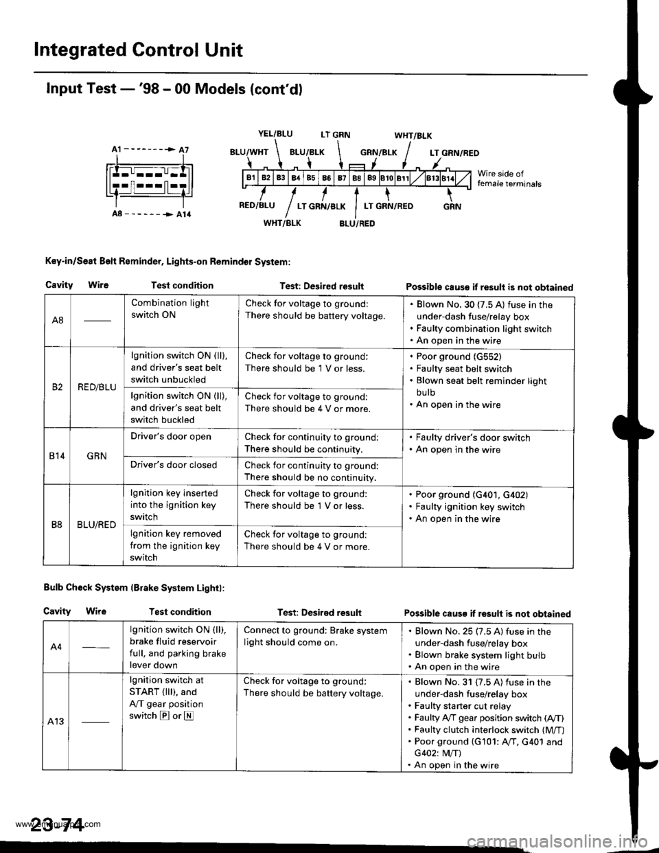
Integrated Control Unit
A1 --------> A7
Input Test -'98 - 00 Models (cont'dl
YEL/BLULT GRNWHT/BLK
GRN/BLKLT GRN/REO
Wire side offemale terminals
A8------->A14WHT/BLK
Key-in/Se8t Beft Reminder, Lights-on Remindol System:
BLU/RED
Cavity WireTest conditionTest: Desired resultPossible caus€ it result is not obtained
Bulb Check System lBrake System Lightl:
Cavity WireTest conditionTest: Desired resultPossible caus€ if result is not obtained
A4
lgnition switch ON (ll),
brake fluid reservoir
full, and parking brake
lever down
Connect to ground: Brake system
light should come on.
Blown No. 25 (7.5 A) fuse in the
under-dash fuse/relay box
Blown brake system light bulb
An open in the wire
A13
lgnition switch at
START ( lll), and
A,/T gear position
switch E or E
Check for voltage to ground:
There should be battery voltage.
Blown No. 31 {7.5 A) fuse in the
under-dash fuse/relay box
Faulty sta rter cut relay
Faulty A,/T gear position switch (A,/T)
Faulty clutch interlock switch (M/T)
Poor ground {G101: AfI. G401 and
G402: M/T)
An open in the wire
23-74
A8
Combination light
switch ON
Check for voltage to ground:
There should be battery voltage.
Blown No. 30 (7.5 A) fuse in the
under-dash fuse/relay box
Faulty combination light switch
An open in the wire
RED/BLU
lgnition switch ON ( ll),
and driver's seat belt
switch unbuckled
Check for voltage to ground:
There should be 1 V or less.
Poor ground {G552)
Faulty seat belt switch
Blown seat belt reminder light
bu lb
An open in the wirelgnition switch ON (ll),
and driver's seat belt
switch buckled
Check for voltage to ground:
There should be 4 V or more.
814GRN
Driver's door openCheck for continuity to ground:
There should be continuity,
. Faulty driver's door switch. An open in the wire
Driver's door closedCheck for continuity to ground:
There should be no continuity.
B8BLU/RED
lgnition key inserted
into the ignition key
swrtch
Check for voltage to ground:
There should be 'l V or less.
Poor ground (G401, G402)
Faulty ignition key switch
An open in the wire
lgnition key removed
from the ignition key
switch
Check for voltage to ground:
There should be 4 V or more.
www.emanualpro.com