Page 890 of 1395
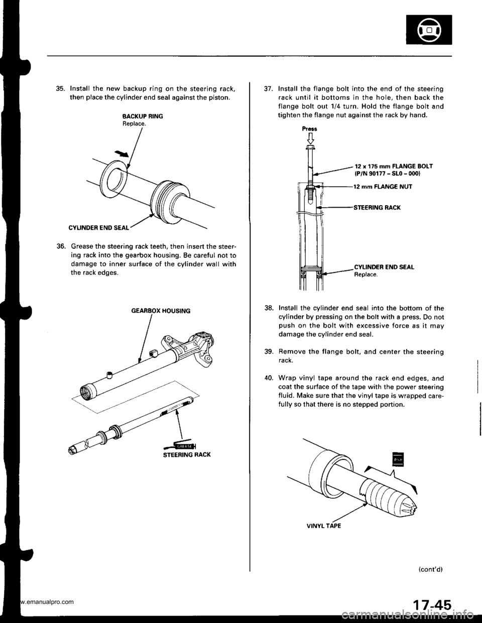
35. Install the new backup ring on the steering rack,
then place the cylinder end seal against the piston.
BACKUP RINGReplace.
Grease the steering rack teeth, then insert the steer-
ing rack into the gearbox housing, Be careful not to
damage to inner surface of the cylinder wall with
the rack edges.
to.
GEARBOX HOUSING
Prers
37. Install the flange bolt into the end of the steering
fack until it bottoms in the hole, then back the
flange bolt out 1/4 turn. Hold the flange bolt and
tighten the flange nut against the rack by hand.
12 x'175 mm FLANGE BOLT
lP/N 90177 - SLo - 0001
12 mm FLANGE NUT
38.
CYLINDER END SEALReplace.
Install the cylinder end seal into the bottom of the
cylinder by pressing on the bolt with a press, Do notpush on the bolt with excessive force as it may
damage the cylinder end seal.
Remove the flange bolt, and center the steering
rack.
Wrap vinyl tape around the rack end edges, and
coat the surface of the tape with the power steering
fluid. Make sure that the vinyl tape is wrapped care-
fully so that there is no stepped portion.
(cont'dl
ia
40.
17-45
www.emanualpro.com
Page 896 of 1395
lnstallation
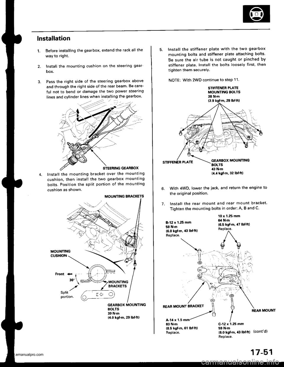
1. Before installing the gearbox, extend the rack all the
waY to right.
2. lnstall the mounting cushion on the steerlng gear-
box.
3. Pass the right side of the steering gearbox above
and through the right side of the rear beam. Be care-
ful not to bend or damage the two power steering
STEERING GEARBOX
Install the mounting bracket over the mounting
cushion. then install the two gearbox mounting
bolts. Position the split portion of the mounting
cushion as shown.
MOUNTING BBACKETS
GEARBOX MOUNTINGBOLTS39 N.m14.0 kgf.m, 29 lbf.ft)
:-
/
5. Install the stiffener plate with the two gearbox
mounting bolts and stiffener plate attaching bolts.
Be sure the air tube is not caught or pinched by
stiffener plate. Install the bolts loosely first. then
tighten them securely.
NOTE: With 2WD continue to step 11.
STIFFENER PLATEMOUNTING BOLTS38 N.m
1.
With 4WD, lower the iack, and return the engine to
the original Position.
lnstall the rear mount and rear mount bracket.
Tighten the mounting bolts in order: A, B and C.
8.12 x 1,25 mm
59 N.m(6.0 kgt.m. *l lb{'ftlReplace.
10 x 1.25 mm6,a N.m
16.5 kst.m, 47 lbl'ft)R€place.
)\^
o(]
17-51
www.emanualpro.com
Page 918 of 1395
Rear Suspension
Hub Bearing Unit Replacement
Note these items during replacement:
. Use only genuine Honda wheel weights for aluminum wheels. Non-genuine wheel weights may corrode and damage
the aluminum wheels.
. Before installing the brake drum, clean the mating surfaces of the rear hub and the brake drum.
. Before installing the wheel, clean the mating surfaces of the brake drum and wheel.
FLANGE BOLI12 x 1,25 mm103 N.m 110.5 kgf.m,76 tbtfr)
BACKING PLATE
SPINDI-E NUT22 x'1.5 mm181 N.m {18.5 kgf.m, 134 lbf.ftlReplace.NOTE: Alter tightening, use a driftpunch to lock the spindle nut shoulderinto the spindle.
BRAKE SHOE
TRAILING ARMCheck {or crackingano oamage.
FLANGE BOLT10 x 1.25 mm64 N'm 16.5 kgf.m, 4? lbt.ft)
Check for crackingano oamage.
BRAKE DRUMCheck for wearano oamage,
WHEEL NUT12 x 1.5 mm108 N.m {11.0 kgt m,80lbtftl
1A-20
www.emanualpro.com
Page 919 of 1395
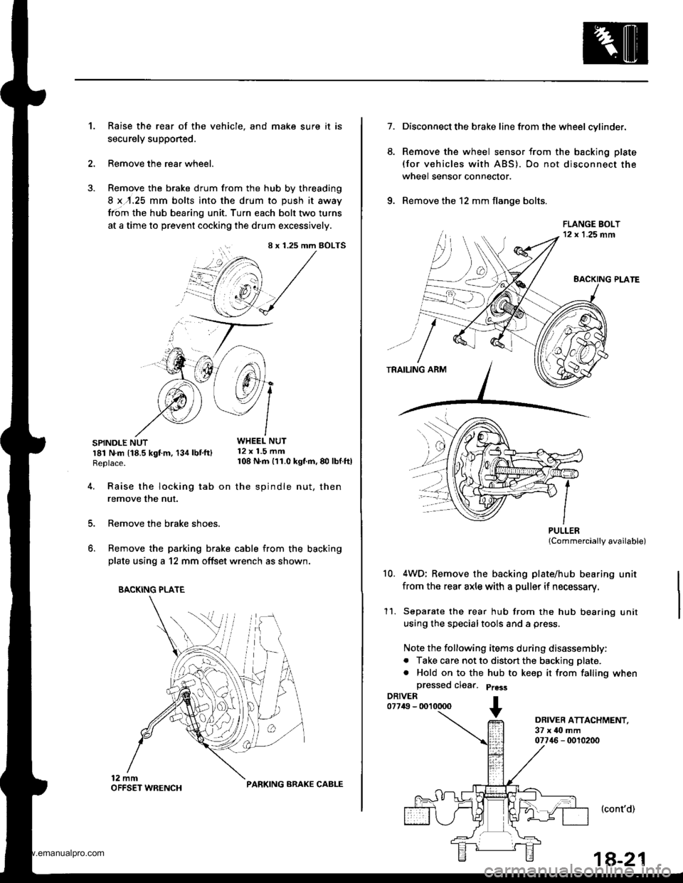
Raise the rear of the vehicle, and make sure it is
securely supponed.
Remove the rear wheel.
Remove the brake drum from the hub by threading
8 x,r.25 mm bolts into the drum to push it away
from the hub bearing unit. Turn each bolt two turns
at a time to prevent cocking the drum excessively.
SPINDLE NUTWHEEL NUT
r81 N.m t18.5 kgt m, 134 lbt'ftl 12 x 1.5 mm
Replace. 108 N m 111.0 kgf'm, 80 lbf ftl
't.
4.
8 x 1.25 mm BOLTS
i+/3 /',1
"@,1 /
.'--7 J-->-
5.
6.
Raise the locking tab on the spindle nut, then
remove the nut.
Remove the brake shoes.
Remove the parking brake cable from the backing
plate using a 12 mm offset wrench as shown.
BACKING PLATE
PARKING ARAKE CABLE
1a-21
7.
6.
Disconnect the brake line from the wheel cylinder.
Remove the wheel sensor from the backing plate
(for vehicles with ABS). Do not disconnect the
wheel sensor connector.
Remove the 12 mm flange bolts.
PULLERlCommercially available)
4WD; Remove the backing plate/hub bearing unit
from the rear axle with a puller if necessary.
Separate the rear hub from the hub bearing unit
using the specialtools and a press.
Note the following items during disassembly:
. Take care not to distort the backing plate.
. Hold on to the hub to keep it from falling when
a
10.
11.
DRIVER ATTACHMENT,37 x ilo mm07746 - 0010200
(cont'd)
www.emanualpro.com
Page 920 of 1395
Rear Suspension
Hub Bearing Unit Replacement (cont'd)
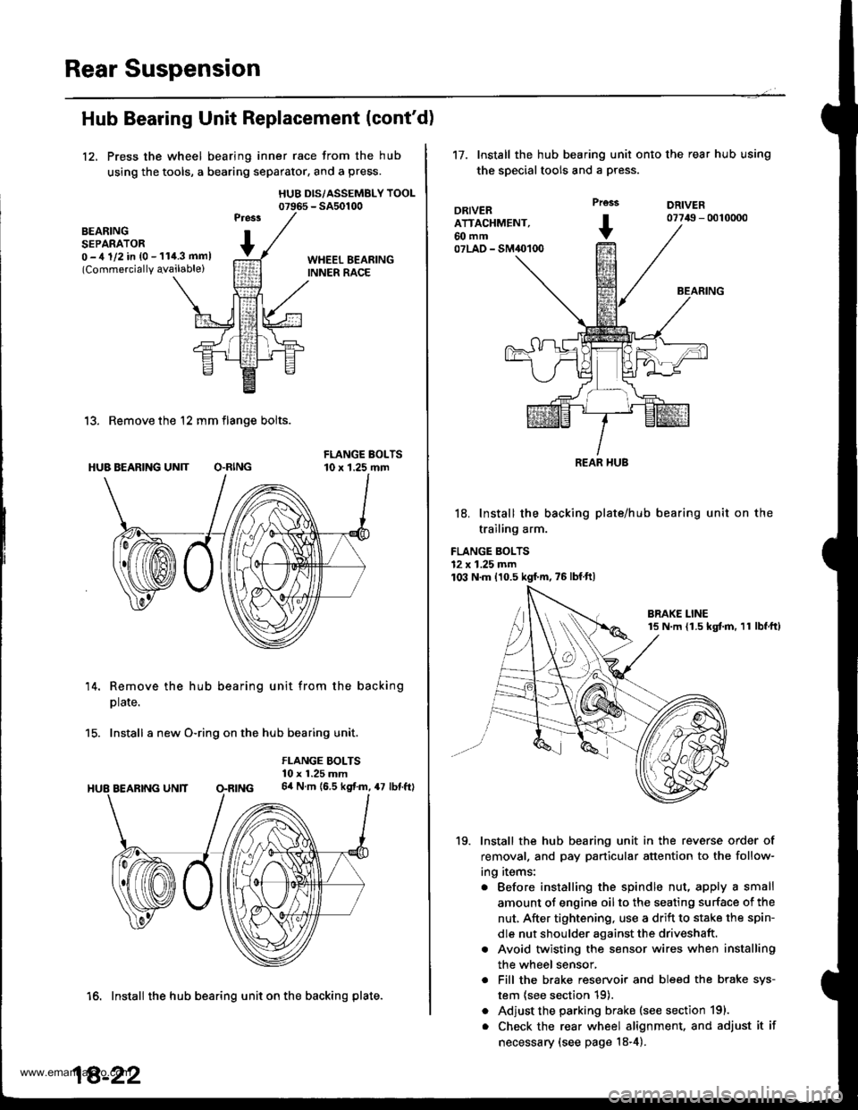
12, Press the wheel bearing inner race from the hub
using the tools, a bearing separator, and a press.
HUB DIS/ASSEMBLY TOOL07965 - SA50100
BEARINGSEPARATOR0 -,t 1/2 in {0 - 11i1.3 mml(Commercially qvailable)
13. Remove the 12 mm flange bolts.
HUB BEARING UN]T O.RING
14. Remove the hub bearing unit from the backing
plate.
15. Install a new O-ring on the hub bearing unit.
FLANGE BOLTS10 x 1.25 mm64 N.m (6.5 kgf.m, 47 lbf.ftl
16. Install the hub bearing unit on the backing plate.
18-22
't7.Install the hub bearing unit onto the rear hub using
the special tools and a press.
DRIVERATTACHMENT,60 mm07LAO - SM40100
Prcss
+
DRIVER07749 - 0010000
BEARING
18. Install the backing plate/hub
trailing arm.
FLANGE BOLTS12 x 1.25 mm103 N.m 110.5 kgf'm,75lbfft)
bearing unit on the
19. Install the hub bearing unit in the reverse order of
removal, and pay particular attention to the follow-
ing items:
. Before installing the spindle nut, apply a small
amount of engine oil to the seating surface of the
nut, After tightening, use a drift to stake the spin-
dle nut shoulder against the driveshaft.
. Avoid twisting the sensor wires when installing
the wheel sensor,
. Fill the brake reservoir and bleed the brake sys-
tem {see section 19).
. Adjust the parking brake (see section 191.
. Check the rear wheel alignment, and adjust it if
necessary (see page 18-4).
REAR HUB
www.emanualpro.com
Page 929 of 1395
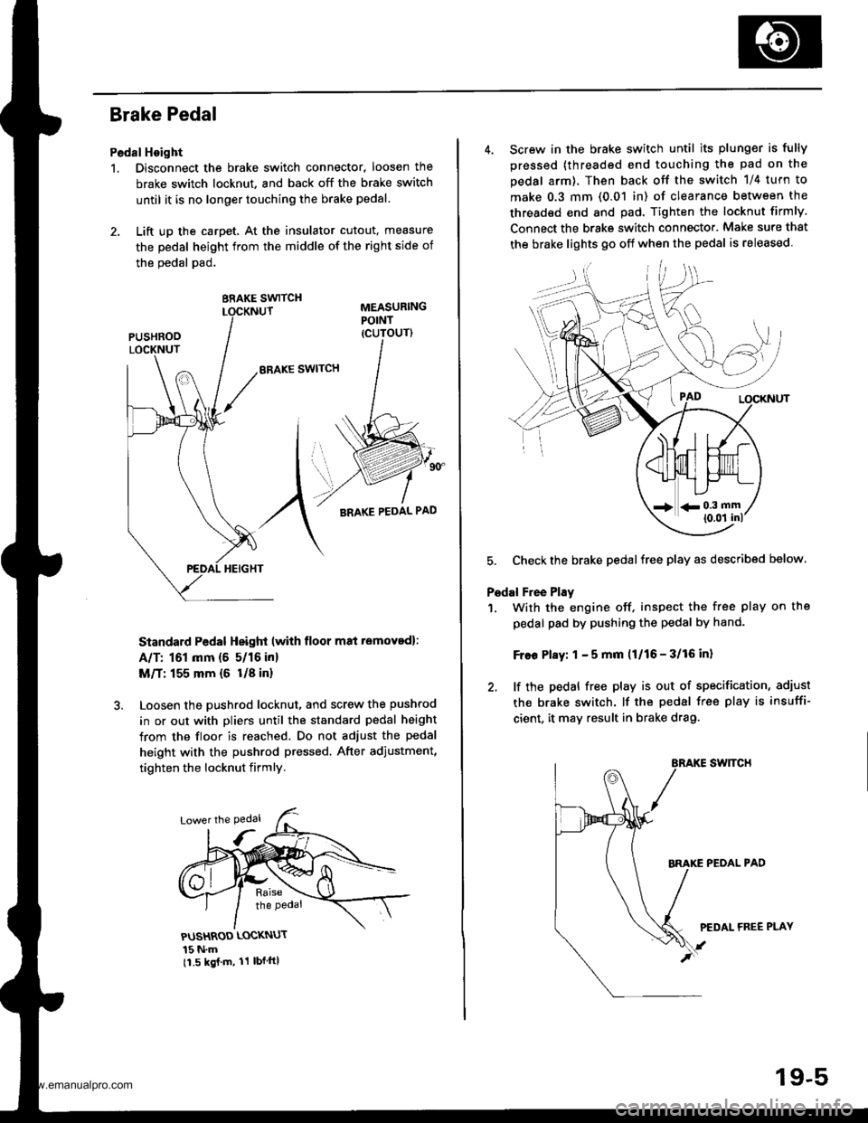
Brake Pedal
Pedal Hoight
1. Disconnect the brake switch connector, loosen the
brake switch locknut, and back off the brake switch
until it is no longer touching the brake pedal.
2. Lift up the carpet, At the insulator cutout, measure
the pedal height from the middle of the right side of
the oedal pad.
BRAKE SWITCH
ERAKE SWITCH
Standard Pedal Height (with floor m8i removed):
A/T: 161 mm (5 5/16 in)
M/T: 155 mm {6 U8 in}
Loosen the pushrod locknut, and screw the pushrod
in or out with pliers until the standard pedal height
from the floor is reached. Do not adjust the pedal
height with the pushrod pressed. After adiustment,
tighten the locknut firmly.
PUSHROD LOCKNUT
15 N.m11.5 kgj m, 11 lbf ftl
4. Screw in the brake switch until its plunger is fully
pressed (threaded end touching the pad on the
pedal arm), Then back otf the switch 1/4 turn to
make 0.3 mm (0.01 in) of clearance between the
threaded end and pad. Tighten the locknut firmly.
Connect the brake switch connecto.. Make sure that
the brake lights 90 off when the pedal is released
5. Checkthe brake pedalfree play as described below
Pedal Free Play
1. With the engine off. inspect the free play on the
pedal pad by pushing the pedal by hand-
Free Play: 1 - 5 mm (1/16 - 3/16 in)
2. lf the pedal free play is out of specification, adiust
the brake switch. lf the pedal free play is insuffi-
cient, it may result in brake drag.
swtTcH
PEOAL PAD
PEDAL FREE PLAY
19-5
www.emanualpro.com
Page 933 of 1395
Front Brake Pads
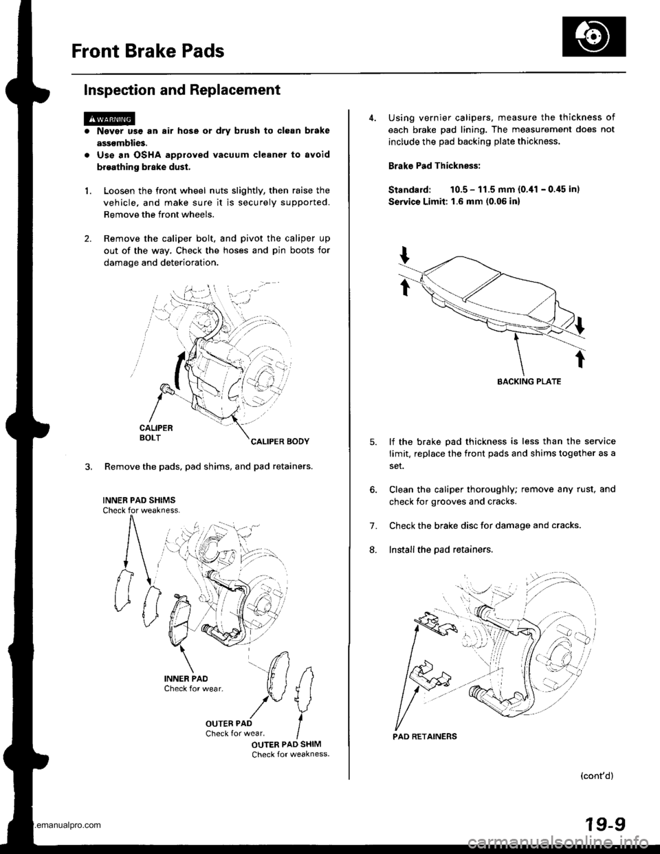
Inspection and Replacement
1.
Nsvgr u9e an air hose or dry brush to clean brake
assemblies.
Use an OSHA approved vacuum cleaner to avoid
broathing brake dust.
Loosen the front wheel nuts slightly, then raise the
vehicle, and make sure it is securely supported.
Remove the front wheels.
Remove the caliper bolt, and pivot the caliper up
out of the way. Check the hoses and pin boots for
damage and deterioration.
CALIPERBOLTCALIPER BODY
3. Remove the pads, pad shims, and pad retainers.
INNEB PAD SHIMSCheck for weakness.
#
IOUTER PAD SHIMCheck for weakness.
i)n.
4. Using vernier calipers, measure the thickness of
each brake pad lining. The measurement does not
include the pad backing plate thickness.
Brake Pad Thickness:
Standard: 10.5 - 11.5 mm {0.,11 - 0.45 in)
Servics Limit: 1.6 mm (0.06 in)
lf the brake pad thickness is less than the service
limit. replace the front pads and shims together as a
set.
Clean the caliper thoroughly; remove any rust, and
check for grooves and cracks.
Check the brake disc for damage and cracks.
Install the pad retainers.
7.
L
(cont'd)
19-9
EACKING PLATE
'.'..i
PAD RETAINERS
www.emanualpro.com
Page 934 of 1395
Front Brake Pads
Inspection and Replacement (cont'dl
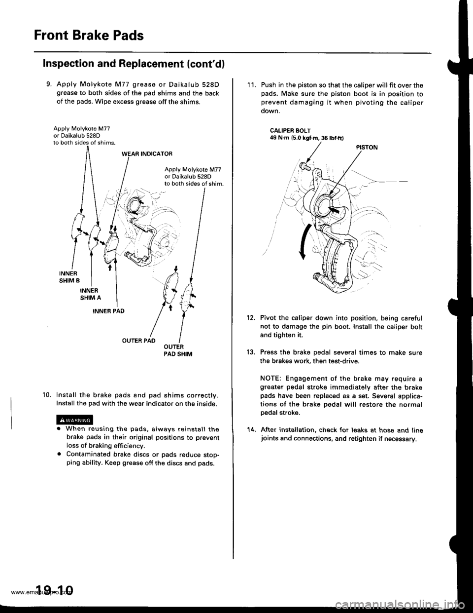
9. Apply Molykote M77 grease or Daikalub 528Dgrease to both sides of the pad shims and the back
of the pads. Wipe excess grease off the shims.
Apply Molykote M77
to both sides of shims.
INOICATOR
Apply Molykote M77or 0aikalub 528Dto both sides of shim.
10.
INNER PAD
OUTER PAD
lnstall the brake pads and pad shims correctly.
Install the pad with the wear indicator on the inside.
. When reusing the pads, always reinstall thebrake pads in their original positions to prevent
loss of braking efficiency.. Contaminated brake discs or pads reduce stop-ping ability. Keep grease off the discs and pads.
19-10
'11. Push in the piston so that the caliper willfit over thepads. Make sure the piston boot is in position toprevent damaging it when pivoting the caliper
down.
CALIPER BOLT49 N.m (5.0 kgf.m, 36 lbf.ftl
13.
Pivot the caliper down into position, being careful
not to damage the pin boot. Install the caliper bolt
and tighten it,
Press the brake pedal several times to make sure
the brakes work, then test-drive.
NOTE: Engagement of the brake may require agreater pedal stroke immediately after the brakepads have been replaced as a set. Several applica-
tions of the brake pedal will restore the normalpedal stroke.
After installation, check for leaks at hose and linejoints and connections, and retighten if necessary.
14.
www.emanualpro.com